Classic Instruments Fuel Link SN34 User manual

Classic Instruments
SN34
Fuel Link
Installation Manual

Revised: March 9, 2020 Page 2
TableofContents
Welcome from the Team at Classic Instruments! .............................................................................................................. 3
Before You Get Started ...................................................................................................................................................... 4
Connecting the Fuel Link ................................................................................................................................................... 4
FuelLinkWiringDiagram................................................................................................................................................................4
Fuel Link Calibration ......................................................................................................................................................... 5
Fuel Link Operating Mode Functionality .......................................................................................................................... 7

Revised: March 9, 2020 Page 3
Welcome from the Team at Classic Instruments!
Our congratulations and appreciation for your purchase of one of the finest quality sets of specialty instruments
ever produced! Your instrument set has been conceived, designed, and manufactured by Classic Instruments, Inc. in
the U.S.A. Each instrument has been tested and certified for accuracy and quality before packaging and shipping.
For trouble-free installation and operation follow the instructions exactly as outlined. Your instruments were
assembled to precise specifications and although each has a seven (7) year warranty covering defective parts and
workmanship – this warranty will not cover instruments or sender units which have been installed incorrectly.
Follow our recommended procedures for installation and proper hookup to maintain the value and appearance of
your instrument set during many future years of accurate and dependable service!
LIMITED WARRANTY
Classic Instruments, Inc. (CI) warrants to the original purchaser that any CI product manufactured or supplied by
CI will be free from defects in material and workmanship under normal use and service for a period of seven (7) years
from date of purchase.
Improper installation, attempted repair or adjustments by other than CI shall void this warranty. Disassembly of
any instruments or senders for whatever reason shall specifically void this warranty.
It’s always easy to look to a part for an issue with your set. Before you conclude that a part may be bad,
thoroughly check your work. Today’s semiconductors and passive components have reached incredibly high
reliability levels, but there is still room for error in our human construction skills. However, on rare occasions a sour
part can slip through. Please be aware that testing can usually determine if the part was truly defective or damaged
by assembly or usage. Don’t be afraid of telling us that you “blew it”, we’re all human and in most cases, replacement
parts are very reasonably priced.
Purchaser requesting a product to be repaired or replaced under warranty must first call CI at 1-800-575-0461
before the return of defective part. Send defective part to 826 Moll Drive, Boyne City, MI 49712, USA. Include a
written description of the failure with defective part.
Purchaser agrees and accepts that under no circumstances will a warranty replacement be furnished until CI has
first received, inspected, and tested the returned part.
All other warranties expressed or implied are hereby excluded including any implied warranty of merchandise and
implied warranty of fitness for a particular purpose. The sole and exclusive remedy for breach of this warranty is
limited to the replacement set forth above.
It is expressly agreed that there shall be no further remedy for consequential or other type of damage, including
any claim for loss of profit, engine damage or injury.
TECHNICAL ASSISTANCE
1-800-575-0461
OR
Visit our website for the latest in gauge design and updates to our installation manual
www.classicinstruments.com
Revised: March 9, 2020 Page 4
Before You Get Started
The Fuel Link has been designed to work with nearly any short sweep fuel gauge (90 degree or less
pointer sweep) and fuel sender combination. It will not work on fuel gauges which have pointer sweeps
greater than 90 degrees. All Classic Instruments fuel gauges are short sweep and are compatible with the
Fuel Link.
The Fuel Link is designed to work with a properly functioning fuel gauge and fuel sender. The Fuel
Link cannot fix a broken component, but can correct inaccuracies from mismatched components.
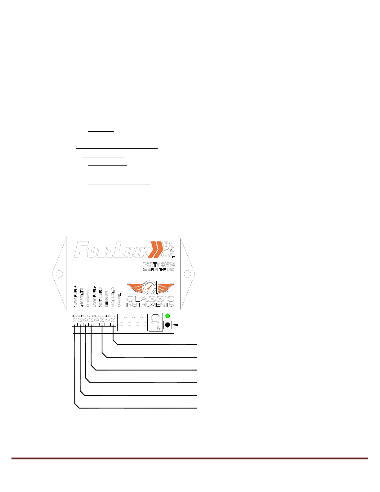
Connecting the Fuel Link
1) Connect the hot wire of an optional low fuel indicator to the Fuel Link terminal marked LOW
FUEL +. If you are not using a low fuel indicator, this terminal is not used.
2) Connect switched +12VDC power to the Fuel Link terminal marked +12 VOLTS.
3) Connect a good ground to the Fuel Link terminal marked GROUND.
4) Connect the ground wire of an optional low fuel indicator to the Fuel Link terminal marked LOW
FUEL -. If you are not using a low fuel indicator, this terminal is not used.
5) Connect the fuel sender signal to the Fuel Link terminal marked SENSOR.
6) Connect the fuel gauge signal post to the Fuel Link terminal marked GAUGE.
Fuel Link Wiring Diagram
7
5
3
1
6
4
2
Fuel Gauge Signal Terminal
Fuel Level Sender
Optional Low Fuel Indicator's Ground
Ground
+12V Switched Power
Optional Low Fuel Indicator's Power
Calibration Pushbutton
Revised: March 9, 2020 Page 5
Fuel Link Calibration
Start with vehicle power OFF.
Press and hold the calibration button and turn vehicle power ON. Once the power is on, release the
button.
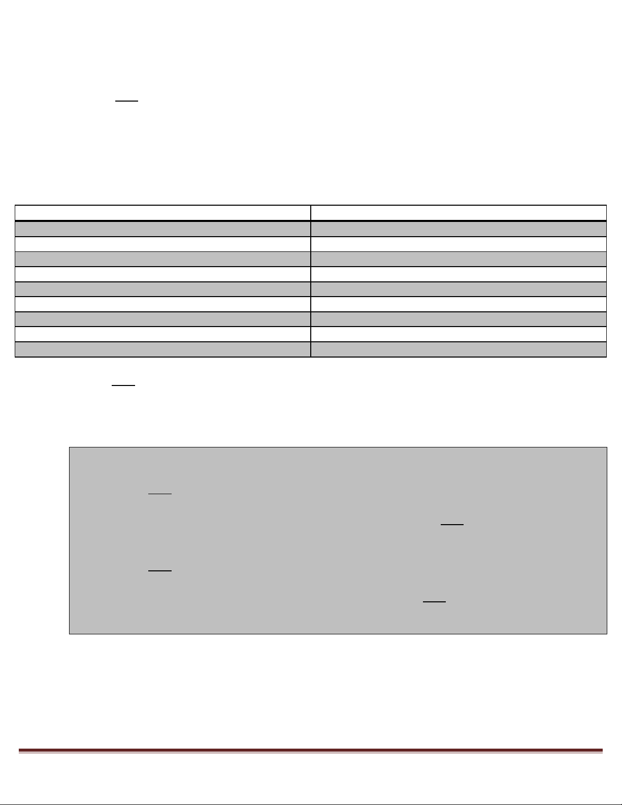
The LED digit will flash t, and change to 1 within two seconds. Tapping the calibration button causes
the display to cycle through 1, 2, 3, 4, 5, 6, 7, 8 (for standard sensors) and A (for custom sensor
range).
o If the selection has previously been set, the display will show that setting upon entering the
sensor calibration mode.
Option Number Sender Resistance Ran
g
e
1 240-33
(
Standard Aftermarket
)
2 0-90
(
GM T
y
pe 1966 to 1998
)
3 0-30
(
GM T
y
pe 1964 and earlier
)
4 16-158
(
Ford T
y
pe 1986 and later
)
5 75-10
(
Ford T
y
pe 1986 and earlier
)
6 90-0
(
To
y
ota and Nissan 1985 and later
)
7 10-180
(
VDO
)
8 40-250
(
GM T
y
pe 1998 and later
)
A
Manuall
y
Entered Resistance Ran
g
e
Push and hold the calibration button for approximately 4 seconds to enter the sensor option indicated
by the LED display on the module. If A is chosen, the display will remain on A for the calibration
step. Otherwise, the display will change to g to show setting is complete and to prepare for the next
calibration step.
o Note: Perform these steps ONLY if option A was selected.
o If A is chosen, then the fuel sender resistance range will need to be manually entered.
o Push and hold the calibration button with A displayed until the LED starts alternating between
t and E.
o Move the fuel sender float to the empty position, then press and hold the calibration button to
set the empty tank value. The display will change to A again to show setting is complete and
to prepare for the next calibration step.
o Push and hold the calibration button again with A displayed until the LED starts alternating
between t and F.
o Move the fuel sender float to the full position, then press and hold the calibration button to set
the full tank value. The display will change to g to show setting is complete and to prepare for
the next calibration step.
The following steps MUST also be completed to successfully calibrate the Fuel Link:

Revised: March 9, 2020 Page 6
Press and hold the calibration button with the LED indicating g until the g starts alternating with E.
The gauge empty indication will now be set.
Press and hold the calibration button to change the fuel gauge’s pointer position. The first time the
button is pressed and held, the fuel level shown on the gauge will decrease (or in some cases
increase). The next time the button is pressed and held, the fuel level shown on the gauge will
change in the opposite direction. The direction the fuel level indicator changes will alternate between
increasing and decreasing every time it is pressed and held.
Once the fuel gauge is indicating empty, wait 8 seconds without pushing the calibration button to
save the calibration. The LED display will change back to g to confirm calibration is saved.
Press and hold the calibration button with the LED indicating g until the g starts alternating with 2.
The gauge 1/4 tank indication will now be set.
Press and hold the calibration button to change the fuel gauge’s pointer position. The first time the
button is pressed and held, the fuel level shown on the gauge will decrease (or in some cases
increase). The next time the button is pressed and held, the fuel level shown on the gauge will
change in the opposite direction. The direction the fuel level indicator changes will alternate between
increasing and decreasing every time it is pressed and held.
Once the fuel gauge is indicating 1/4, wait 8 seconds without pushing the calibration button to save
the calibration. The LED display will change back to g to confirm calibration is saved.
Press and hold the calibration button with the LED indicating g until the g starts alternating with 5.
The gauge 1/2 tank indication will now be set.
Press and hold the calibration button to change the fuel gauge’s pointer position. The first time the
button is pressed and held, the fuel level shown on the gauge will decrease (or in some cases
increase). The next time the button is pressed and held, the fuel level shown on the gauge will
change in the opposite direction. The direction the fuel level indicator changes will alternate between
increasing and decreasing every time it is pressed and held.
Once the fuel gauge is indicating 1/2, wait 8 seconds without pushing the calibration button to save
the calibration. The LED display will change back to g to confirm calibration is saved.
Press and hold the calibration button with the LED indicating g until the g starts alternating with 7.
The gauge 3/4 tank indication will now be set.
Press and hold the calibration button to change the fuel gauge’s pointer position. The first time the
button is pressed and held, the fuel level shown on the gauge will decrease (or in some cases
increase). The next time the button is pressed and held, the fuel level shown on the gauge will
change in the opposite direction. The direction the fuel level indicator changes will alternate between
increasing and decreasing every time it is pressed and held.
Once the fuel gauge is indicating 3/4, wait 8 seconds without pushing the calibration button to save
the calibration. The LED display will change back to g to confirm calibration is saved.
Press and hold the calibration button with the LED indicating g until the g starts alternating with F.
The gauge full tank indication will now be set.
Press and hold the calibration button to change the fuel gauge’s pointer position. The first time the
button is pressed and held, the fuel level shown on the gauge will decrease (or in some cases
increase). The next time the button is pressed and held, the fuel level shown on the gauge will
change in the opposite direction. The direction the fuel level indicator changes will alternate between
increasing and decreasing every time it is pressed and held.
Once the fuel gauge is indicating full, wait 8 seconds without pushing the calibration button to save
the calibration. The LED display will change to C to confirm calibration is saved.
Press and hold the calibration button with the LED indicating C to exit calibration mode.

Revised: March 9, 2020 Page 7
Fuel Link Operating Mode Functionality
At power up, the correct fuel level will be displayed within 2 seconds.
The Fuel Link keeps a running average of the sensed fuel level values to keep sloshing of fuel from
moving the gauge indication significantly. Keep in mind this will cause the gauge to move
slowly, even if the sender reading is changing rapidly.
The low fuel indicator will turn on when 10% or less fuel remains. It will turn off when the fuel level
rises back above 15%.
The LED display is off and the calibration button has no effect while in operating mode.
Table of contents
Other Classic Instruments Automobile Accessories manuals

Popular Automobile Accessories manuals by other brands

Cap-Pack Sport
Cap-Pack Sport CPS-5 Easy installation guide

Larson Electronics
Larson Electronics MMP-F150-2013 installation manual

Aries
Aries 2157002 installation manual

Whispbar
Whispbar K742W Fitting instructions

Prorack
Prorack K482 Fitting Instructions for Basic Carrier

dirna Bergstrom
dirna Bergstrom Bycool Slim Fit DAF Mounting instructions


Westfalia
Westfalia 305 221 Installation and operation instructions

Kuda
Kuda 096630 Installation instruction

Xingjialin Electronics
Xingjialin Electronics DS-339 installation instructions

Nav TV
Nav TV C.O.D-F50 manual

Monster
Monster MPC FX ICRUZ Installation & user guide

Yakima
Yakima BoatLoader EVO installation instructions