Classic Instruments ULTIMATE User manual
www.classicinstruments.com <#>
Handcrafted in America Since 1977 with the Simple Goal of Perfection
ULTIMATE
INSTALLATION MANUAL
“The Wolrd’s Smartest Speedometer”
®


Welcome From the Team at Classic Instruments!
Our congratulations and appreciation for your purchase of the finest quality set of
specialty instruments ever produced! Your instrument set has been conceived, designed, and
manufactured by Classic Instruments, Inc. in the U.S.A. Each instrument has been tested and
certified for accuracy and quality before packaging and shipping.
For trouble-free installation and operation, follow the instructions exactly as
outlined. Your instruments were assembled to precise specifications and although each has a
five (5) year warranty covering defective parts and workmanship – this warranty will not
cover instruments or sending units which have been installed incorrectly.
LIMITED WARRANTY
Classic Instruments, Inc. (CI) warrants to the original purchaser that any CI product
manufactured or supplied by CI will be free from defects in material and workmanship under
normal use and service for a period of five (5) years from date of purchase.
Improper installation, use of sending units other than CI’s or attempted repair or
adjustments by other than CI shall void this warranty. Disassembly of any instruments or
senders for whatever reason shall specifically void this warranty.
Purchaser requesting a product to be repaired or replaced under warranty must first
call CI at 1-800-575-0461 before the return of defective part. Send defective part either to
1299 M-75, through UPS, or to P.O. Box 411 through U.S. Mail, Boyne City, MI 49712,
USA. Include a written description of the failure with defective part.
Purchaser agrees and accepts that under no circumstances will a warranty
replacement be furnished until CI has first received, inspected, and tested the returned part.
All other warranties expressed or implied are hereby excluded including any implied
warranty of merchandise and implied warranty of fitness for a particular purpose. The sole
and exclusive remedy for breach of this warranty is limited to the replacement set forth above.
It is expressly agreed that there shall be no further remedy for consequential or other
type of damage, including any claim for loss of profit, engine damage or injury.
TECHNICAL ASSISTANCE 1-800-575-0461
OR
Visit our new website for the latest in gauge design and updates to our
installation manual at:
WWW.CLASSICINSTRUMENTS.COM
www.classicinstruments.com Ultimate Installation Manual ~ 3

Table of Contents
Welcome From the Team at Classic Instruments! ______________ 3
Table of Contents ________________________________________ 4
Ultimate Speedometer Wire Diagrams________________________ 5
Using Classic Instruments Pulse Signal Generator _______________ 5
Using Transmission Vehicle Speed Sensor ______________________ 6
Using ECM Speed Signal ____________________________________ 7
Wiring the Ultimate Speedometer ___________________________ 8
Setting Up Your Speedometer and Tachometer________________ 10
Entering Setup Mode: _____________________________________ 10
Tachometer Setup: ________________________________________ 11
Cylinder Select: _______________________________________________11
Tachometer Signal Type: ________________________________________12
Speedometer Setup: _______________________________________ 13
Speed Auto Calibrate:___________________________________________13
Real-Time Speed Adjust: ________________________________________14
4 ~ Ultimate Installation Manual www.classicinstruments.com
Ultimate Speedometer Wire Diagrams
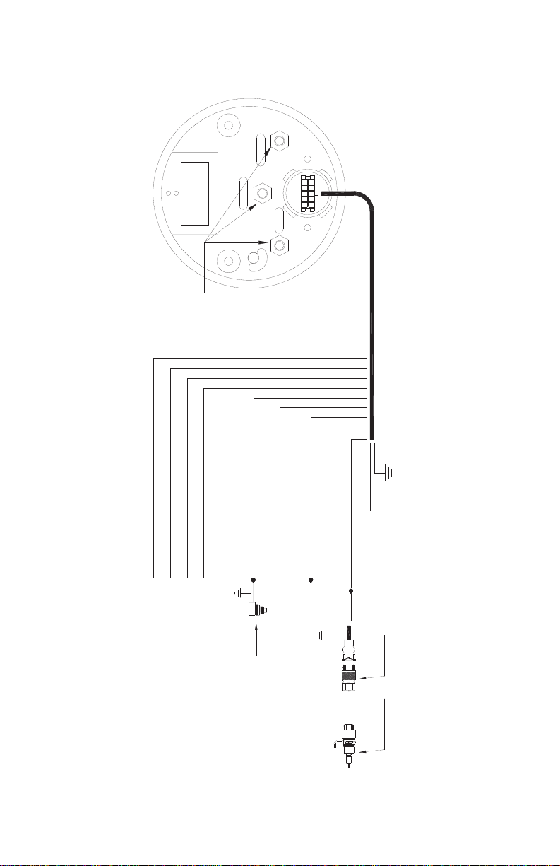
Using Classic Instruments Pulse Signal Generator
SIG
GNDB+
A123
4
No Connection
Good Chassis Ground [Black]
+12VDC Switched [Pink]
Pulse Signal Generator Power [Red]
(use only with SN16 or SN16FD)
Red
Black
Good Chassis Ground
White
Speedometer Signal Input [Purple]
SN16
OR
SN16FD
Tachometer Signal Input [White]
Function Button Input [Brown]
Good Chassis Ground
Pushbutton
Gauge Lights [Grey]
Hi Beam Indicator [Green/White](if supplied)
Right Turn Indicator [Purple/White](if supplied)
Left Turn Indicator [Blue/White](if supplied)
www.classicinstruments.com Ultimate Installation Manual ~ 5

Using Transmission Vehicle Speed Sensor
Chassis Ground
(ground at same place as Black wire)
SIG
GNDB+
A123
4
No Connection
Good Chassis Ground [Black]
+12VDC Switched [Pink]
Pulse Signal Generator Power [Red]
(use only with SN16 or SN16FD)
Speedometer Signal Input [Purple]
(Not Used) Transmission Electronic
Vehicle Speed Sensor
Tachometer Signal Input [White]
Function Button Input [Brown]
Good Chassis Ground
Pushbutton
Gauge Lights [Grey]
Hi Beam Indicator [Green/White](if supplied)
Right Turn Indicator [Purple/White](if supplied)
Left Turn Indicator [Blue/White](if supplied)
6 ~ Ultimate Installation Manual www.classicinstruments.com

Using ECM Speed Signal
SIG
GNDB+
A123
4
No Connection
Good Chassis Ground [Black]
+12VDC Switched [Pink]
Pulse Signal Generator Power [Red]
(use only with SN16 or SN16FD)
Speedometer Signal Input [Purple]
(Not Used)
ECM Computer
Tachometer Signal Input [White]
Function Button Input [Brown]
Good Chassis Ground
Pushbutton
Gauge Lights [Grey]
Hi Beam Indicator [Green/White](if supplied)
Right Turn Indicator [Purple/White](if supplied)
Left Turn Indicator [Blue/White](if supplied)
Speed Signal
(Usually a Green Wire)
www.classicinstruments.com Ultimate Installation Manual ~ 7

Wiring the Ultimate Speedometer
Step 1:
Connect the pink wire of the instrument harness to
a +12VDC switched power source.
Step 2:
Connect the black wire of the instrument harness
to a good chassis ground.
Step 3:
Connect the speedometer signal.
Mechanical 2-wire pulse signal generator:
A. Connect one wire of the signal generator to
the purple wire of the instrument harness.
B. Connect the other wire of the signal generator
to a good chassis ground.
Mechanical 3-wire pulse signal generator:
A. Connect the white wire of the signal generator
to the purple wire of the instrument harness.
B. Connect the black wire of the signal generator
to a good chassis ground.
C. Connect the red wire of the signal generator
to the red wire of the instrument harness.
Electronic (built-in) speed sensor or magnetic sensor:
A. Connect one of the wires from the sensor to
the purple wire of the instrument harness
B. Connect the other wire from the sensor to a
good chassis ground.
Computer speed signal:
A. Connect the computer speed signal wire to the
purple wire of the instrument harness.
Step 4:
Connect the white wire of the instrument harness
to the tachometer signal.
See Table 1
Step 5:
Connect the grey wire of the instrument harness to
a +12VDC dash light power source.
Step 6:
Connect the function / setup pushbutton.
A. Connect the brown wire of the instrument harness
to one lead of the function / setup pushbutton.
B. Connect the other lead of the function / setup
pushbutton to a good chassis ground.
8 ~ Ultimate Installation Manual www.classicinstruments.com

Step 7:
Connect the green/white wire of the instrument
harness to the +12VDC high beam indicator signal.
(if
supplied)
Step 8:
Connect the blue/white wire of the instrument
harness to the +12VDC left turn indicator signal.
(if
supplied)
Step 9:
Connect the violet/white wire of the instrument
harness to the +12VDC right turn indicator signal.
(if
supplied)
Table 1
Ignition System Tachometer Signal Source
Standard Points & Condenser
System
Negative side of coil (usually
marked “-“)
GM – HEI (High Energy Ignition)
System
Terminal marked “TACH” on coil side
of distributor cap.
MSD (Multiple Spark Discharge)
System
TACH post on MSD box. If there
isn’t a box, signal comes from
negative side of coil. If tachometer
doesn’t respond correctly, your MSD
system may require a MSD TACH
adapter part #8910 or #8920.
Contact MSD for the correct adapter
for your application.
Vertex Magneto System
“KILL” terminal on side of Vertex
magneto body. An external
adapter such as a MSD Pro Mag
Tach Converter #8132 may be
required.
Mallory Ignition System
Negative side of coil (usually
marked “-“) I
Important!
Some
Mallory ignition systems require the
tachometer to be set at the 4-
cylinder setting.
ECM (computer) Tachometer Signal
Signal comes from the computer.
You may need to set the
tachometer at the
4-cylinder setting.
All Other Ignition Systems
Please look at the owner’s manual
for the location of the tachometer
signal.
www.classicinstruments.com Ultimate Installation Manual ~ 9

Setting Up Your Speedometer and Tachometer
Speedometer / Tachometer Setup Option Menu
Tach Pointer
Location Setup Option Description
1000 RPM Tachometer
Cylinder Setup Sets number of cylinders.
2000 RPM Tachometer Signal
Type Selects between 5V and 12V
tachometer signal.
3000 RPM Speed Auto
Calibrate Calibrates speed using an exact marked
mile.
4000 RPM Real-Time Speed
Adjust Manually increase or decrease speed.
8000 RPM Exit Exit setup
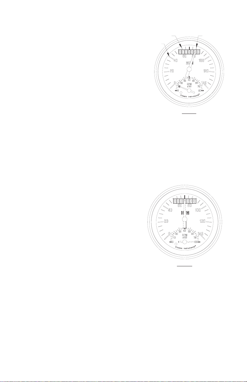
Entering Setup Mode:
1) Start with the power off. While
pressing the function button,
start the vehicle’s engine.
Release the function button
when the engine is running
and the speedometer
pointer is at 70MPH.
2) The tachometer will point to
1000 RPM and the
speedometer will point at 70MPH
once you have successfully entered
the setup mode. F
Fig. 1
3) Pressing and releasing the
function button will cycle
through the setup options.
4) Pressing and holding
(approx. 4 seconds) the
function button will select
the current setup option
that the tachometer is
indicating.
5) When setup is complete, select
the exit option (8000 RPM) then
press and hold the function button.
Fig. 2
FIG. 1
FIG. 2
10 ~ Ultimate Installation Manual www.classicinstruments.com
Tachometer Setup:
Cylinder Select:
1) Enter setup mode.
2) Press and release the
function button until
the tachometer points
to 1000 RPM
(tachometer cylinder
setup option). F
Fig. 3
3) Press and hold the
function button to enter the
tachometer cylinder setup
mode. The speedometer will point to the current
cylinder number setting (40 MPH for 4 cylinders, 60
MPH for 6 cylinders, etc…).
4) Press and release the function button until the
correct setting is selected.
5) Press and hold the function button to save the
setting. The speedometer pointer will again point
up and the tachometer will point to 8000 RPM
(exit). Tachometer
cylinder selection is
now set.
6) If you are finished
making setup
changes, press and
hold the function
button with the
tachometer pointing
to 8000 RPM to exit
setup mode. F
Fig. 4
FIG. 3
8 CYL.
6 CYL.
4
CYL.
FIG. 4
www.classicinstruments.com Ultimate Installation Manual ~ 11

Tachometer Signal Type:
1) Enter setup mode.
2) Press and release
the function button
until the tachometer
points to 2000
RPM (tachometer
signal type option).
Fig. 5
3) Press and hold the
function button to enter the
tachometer signal type mode. The speedometer
will point to the current setting (50 MPH for 5V
signal or 120 MPH for 12V signal).
Note: Use 5V
setting if tachometer signal comes from a
computer. For any other signal use 12V.
4) Press and release the function button until the
correct tachometer signal type setting is selected.
5) Press and hold the function button to save the
setting. The speedometer pointer will again point
up and the tachometer will point to 8000 RPM
(exit). Tachometer signal type is now set.
6) If you are finished making
setup changes, press
and hold the function
button with the
tachometer pointing
to 8000 RPM to exit
setup mode. F
Fig. 6
FIG. 5
12V
5V
FIG. 6
12 ~ Ultimate Installation Manual www.classicinstruments.com

Speedometer Setup:
There are two ways to calibrate the speedometer. Speed auto
calibrate (using an exact marked mile) and real-time speed adjust
(manually adjust speed up or down). It is recommended you use the
speed auto calibrate option first and then make any fine tune
adjustments using the real-time speed adjust option.
Speed Auto Calibrate:
1) Enter setup
mode.
2) Press and release the
function button until
the tachometer
points to 3000 RPM
(speed auto
calibrate option). F
Fig.
3) Press and hold the
function button to enter the
speed auto calibrate mode. The speedometer
will point to 30 MPH (on a 140 MPH
speedometer) indicating you are in speed auto
calibrate mode.
4) Begin driving the measured mile. The tachometer
will operate as normal but the odometer will not
move. When a speed signal is detected, the
speedometer will point to 45 MPH. If a speed
signal is NOT detected, the speedometer will
continue to point at 30 MPH.
5) At the end of the measured mile, press and hold
the function button. The speedometer will again
point up and the
tachometer will point
to 8000 RPM (exit).
The speedometer is
now calibrated.
6) If you are finished
making setup
changes, press and
hold the function
button with the
tachometer pointing to 8000
RPM to exit setup mode. F
Fig. 8
FIG. 7
No
Signal
Si
gna
lD
e
t
ec
t
e
d
FIG. 8
www.classicinstruments.com Ultimate Installation Manual ~ 13

Real-Time Speed Adjust:
1) Enter setup mode.
2) Press and release the
function button until
the tachometer
points to 4000
RPM (real-time
speed adjust
option). F
Fig. 9
3) Press and hold the
function button to enter
the real-time speed adjust
mode.
4) Begin driving the vehicle at a steady known
speed (using a GPS or pacing another vehicle).
The tachometer will remain at 4000 RPM to
indicate the gauge is in real-time speed adjust
mode.
5) Pressing the function button will begin to increase
the speed reading until the button is released.
6) The next time the function button is pressed the
speed reading will decrease.
7) Continue adjusting the speedometer reading until
the correct speed is achieved.
8) If no adjustments are made for 8 seconds, the
current calibration setting will be saved. The
speed setting may still be adjusted after this until
the key is turned off and will be saved again after
8 seconds of function button inactivity. When
finished adjusting the speed, bring the vehicle to
a stop and turn the key off to exit the setup
mode.
FIG. 9
14 ~ Ultimate Installation Manual www.classicinstruments.com

Notes:

www.classicinstruments.com
PO Box 411, 1299 M-75 South
Boyne City, Michigan 49712 USA
Technical Assistance 800-575-0461
®
Handcrafted in America Since 1977
with the Simple Goal of Perfection
Rev. 02, November 2008
Table of contents
Other Classic Instruments Automobile Accessories manuals

Popular Automobile Accessories manuals by other brands

Front Runner
Front Runner SSBS008 quick start guide

ULTIMATE SPEED
ULTIMATE SPEED UAMM 12 B2 operating instructions

SoundGate
SoundGate SDSHOND installation instructions

ProRacing
ProRacing P1 Performante installation instructions

Red Hawk
Red Hawk ACC-RR06 installation instructions

Steel mate
Steel mate PTS810 V10 manual


