HHO Plus CCPWM60A User manual

CC
PWM6
HHO
Hydrogen on Demand Dual Fuel Generator Systems
PWM6
0A –
Installation Manual
Hydrogen on Demand Dual Fuel Generator Systems
Installation Manual
Hydrogen on Demand Dual Fuel Generator Systems

CONTENTS
1 Disclaimer
2 Safety Precautions
3 Parts List
4 Technical Specifications
5 Pulse Width modulation
6 Main Features
7 Electrical Connections
8 Front Panel
9
Configuration Panel. Setting the values
10 Water Level Sensor
CCPWM60A –
Installation Manual
Configuration Panel. Setting the values
Installation Manual
2
3
3
3
4
5
5
5
7
7
9

1 Disclaimer
When purchasing this
device, you are held responsi
operation of this device. The manufacturer or sell
personal harm or property dama
ge. Thank you for purchasing
Power Device. Please read
contents carefully
before getting started.
2
Safety Precautions
Read and follow these safety precautions to avoid hazards. If you do not understand these instructions or do
not like to work on vehicles, please have a qualified mechanic do the installation for you. Incorrectly installing
or using the CCPWM60A and/or the
HHO System may result in serious damage to you and/or your vehicle.
It should take approximately
half an hour
the installation. Be sure to work outside, no smoking at any time during th
is off and very importantly, not hot.
Your HHO System do not store hydrogen, subsequently there is no fire hazard when installed properly.
However water electrolysis generates Hydrogen, an explosive gas, which means
match or smoke near or in front of the generators output
Be careful with the generator working when the car is not moving. A small amount of hydrogen can
accumulate in the air intake of the motor a
Be sure to wear goggles and rubber gloves and only use professional tools; use common sense and general
safety procedures used for any work carried out on automotive installations and maintenance.
3 Parts List
The CCPWM60A package includes
the following items:
1 CCPWM60A
Constant Current
3 Yellow Female Spade Connectors.
CCPWM60A –
Installation Manual
device, you are held responsi
ble for any damage that may occ
operation of this device. The manufacturer or sell
er are not held liable and hold
ge. Thank you for purchasing
our CCPWM60
A
contents carefully
in order
to understand the installing and operation procedures
Safety Precautions
Read and follow these safety precautions to avoid hazards. If you do not understand these instructions or do
not like to work on vehicles, please have a qualified mechanic do the installation for you. Incorrectly installing
HHO System may result in serious damage to you and/or your vehicle.
half an hour
to install this unit, so ensure that you have enough time to complete
the installation. Be sure to work outside, no smoking at any time during th
e installation; make sure the engine
Your HHO System do not store hydrogen, subsequently there is no fire hazard when installed properly.
However water electrolysis generates Hydrogen, an explosive gas, which means
match or smoke near or in front of the generators output
- the water tank
could
Be careful with the generator working when the car is not moving. A small amount of hydrogen can
accumulate in the air intake of the motor a
nd could explode if you smoke or use an open flame near it.
Be sure to wear goggles and rubber gloves and only use professional tools; use common sense and general
safety procedures used for any work carried out on automotive installations and maintenance.
the following items:
Constant Current
Automatic Power Switch Detection;
3 Yellow Female Spade Connectors.
Installation Manual
3
ble for any damage that may occ
ur during installation or
er are not held liable and hold
no responsibility for any
A
Constant Current Automatic
to understand the installing and operation procedures
Read and follow these safety precautions to avoid hazards. If you do not understand these instructions or do
not like to work on vehicles, please have a qualified mechanic do the installation for you. Incorrectly installing
HHO System may result in serious damage to you and/or your vehicle.
to install this unit, so ensure that you have enough time to complete
e installation; make sure the engine
Your HHO System do not store hydrogen, subsequently there is no fire hazard when installed properly.
However water electrolysis generates Hydrogen, an explosive gas, which means
that you should never light a
could
blow up!
Be careful with the generator working when the car is not moving. A small amount of hydrogen can
nd could explode if you smoke or use an open flame near it.
Be sure to wear goggles and rubber gloves and only use professional tools; use common sense and general
safety procedures used for any work carried out on automotive installations and maintenance.

4
Technical Specifications
Direct connection from Battery
60A Max Powersupply;
LCD Module Monochrome Display Screen:
Automatic detection of
battery voltage and auto configuration for: +12V/+24V power supply;
Quad operational chip sensor with
Auto power ON when the Engine is running;
3 Seconds
delay PWM control, after Engine ON is detected;
Auto Power OFF when Engine is turned OFF;
Soft PWM startup to the max Ampere out power supply;
Embedded trimmer for PW
M control: from 0% to 100% HHO CELL power supply;
Logical IC sensor, MUST be powered with 2 wires DIRECT from the battery;
Embedded 3
way power barrier: Positive, G
Optional Water tank sensor switch embedded on system
Frequency: 36kHz
Water Level Sensor
CCPWM60A –
Installation Manual
Technical Specifications
Direct connection from Battery
and Input to HHO CELL generator,
without external relays;
LCD Module Monochrome Display Screen:
Voltmeter + Ammeter
+ Cell Charge information
battery voltage and auto configuration for: +12V/+24V power supply;
Quad operational chip sensor with
1% tolerance Zenner voltage detector;
Auto power ON when the Engine is running;
delay PWM control, after Engine ON is detected;
Auto Power OFF when Engine is turned OFF;
Soft PWM startup to the max Ampere out power supply;
M control: from 0% to 100% HHO CELL power supply;
Logical IC sensor, MUST be powered with 2 wires DIRECT from the battery;
way power barrier: Positive, G
round, Negative from Cell (C
ELL
Optional Water tank sensor switch embedded on system
;
Edit Buttons
Electric cables
Installation Manual
4
without external relays;
+ Cell Charge information
;
battery voltage and auto configuration for: +12V/+24V power supply;
M control: from 0% to 100% HHO CELL power supply;
Logical IC sensor, MUST be powered with 2 wires DIRECT from the battery;
ELL
– OUT);
Edit Buttons

5
Pulse Width modulation
Pulse Width Modulation
is a method of transmitting information on a series of pulses, changing the
frequency, rather than a continuously varying analog signal. It will allow you to control the amperage going
into the generator in a very easy way. This ability keeps the cell run
prolongs the life of the cell while increasing the HHO output
Efficiency:
HHO generators will run cooler than standard linear power amps, requiring substantially less heat
sink mass;
Amperage control: the control of
the amperage going into the generator will be very easy to control. The
ability to control the amperage keeps the cell running at cool operating temperatures and prolongs the life of
the cell while increasing the HHO output.
6
Main Features
NEW TECHNOLOGY: The
CCPWM60A
the same amperage and HHO production regardless the electrolyte concentration, water temperature or
water levels. The CCPWM is the best solution for the professional market
of error. We can put more or less electrolyte and the amperage and HHO production will always be the same.
The CCPWM60A is also
designed for making the automatic power supply of the HHO System without the need
for relays or picking up the signal from the alternator/ignition key, making the system safer to use and easier
to install. In general the new CC
PWM6
- Engine is stopped –
voltage in car is
- Engine isworking –
voltage in car is
The CCPWM60A auto-
detect when the car engine is running and automatically switches ON the HHO
without any additional requirements. The device will automatically power OFF when the car engine is turned
OFF or not running.
The CC
PWM is also capable to control a water level sensor inserted in the water tank turning the system OFF
when the
level drops from a certain point.
7
Electrical Connections
1. Make sure your engine is not
r
2. Mounttheproductasnearoft
he
do notmountitoverthe ba
ttery
3. In the back of the
CCPWM60A there is a sticker to help you with the connections
CCPWM60A –
Installation Manual
Pulse Width modulation
is a method of transmitting information on a series of pulses, changing the
frequency, rather than a continuously varying analog signal. It will allow you to control the amperage going
into the generator in a very easy way. This ability keeps the cell run
ning at cool operating temperatures and
prolongs the life of the cell while increasing the HHO output
HHO generators will run cooler than standard linear power amps, requiring substantially less heat
the amperage going into the generator will be very easy to control. The
ability to control the amperage keeps the cell running at cool operating temperatures and prolongs the life of
the cell while increasing the HHO output.
Main Features
CCPWM60A
(Constant Current Pulse Width Modulator)
the same amperage and HHO production regardless the electrolyte concentration, water temperature or
water levels. The CCPWM is the best solution for the professional market
because there will be no possibility
of error. We can put more or less electrolyte and the amperage and HHO production will always be the same.
designed for making the automatic power supply of the HHO System without the need
for relays or picking up the signal from the alternator/ignition key, making the system safer to use and easier
PWM6
0A will work based on the
voltage of the car:
voltage in car is
below 12,8V – PWM is not working;
voltage in car is
above 13V – PWM is working.
detect when the car engine is running and automatically switches ON the HHO
without any additional requirements. The device will automatically power OFF when the car engine is turned
PWM is also capable to control a water level sensor inserted in the water tank turning the system OFF
level drops from a certain point.
Electrical Connections
r
unning duringinstallation;
he
batteryaspossible(maximum3meters),pro
vid
ttery
;
CCPWM60A there is a sticker to help you with the connections
Installation Manual
5
is a method of transmitting information on a series of pulses, changing the
frequency, rather than a continuously varying analog signal. It will allow you to control the amperage going
ning at cool operating temperatures and
HHO generators will run cooler than standard linear power amps, requiring substantially less heat
the amperage going into the generator will be very easy to control. The
ability to control the amperage keeps the cell running at cool operating temperatures and prolongs the life of
will allow you to have always
the same amperage and HHO production regardless the electrolyte concentration, water temperature or
because there will be no possibility
of error. We can put more or less electrolyte and the amperage and HHO production will always be the same.
designed for making the automatic power supply of the HHO System without the need
for relays or picking up the signal from the alternator/ignition key, making the system safer to use and easier
voltage of the car:
detect when the car engine is running and automatically switches ON the HHO
System,
without any additional requirements. The device will automatically power OFF when the car engine is turned
PWM is also capable to control a water level sensor inserted in the water tank turning the system OFF
vid
ingthatitiswell fixed.Please
CCPWM60A there is a sticker to help you with the connections
:

a. Connect the BATT
ERY
b. Connect theBATTERY
+
c. Connect the CELL-
OUT
4. Only use 6mm sectioncablei
ny
cables in the male pins according to the previous picture
Please refer to the illustrations
below for typical configuration of the electrical connections of the CCPWM60A:
Red –
Positive Battery
Blue –
Negative from Cell
CCPWM60A –
Installation Manual
ERY
-to the negative terminal of the battery;
+
to the positive terminal of the battery;
OUT
- thenegative cable coming fromtheHH
O Cell.
ny
ourinstallation. Use the Yel
low Female spade C
cables in the male pins according to the previous picture
.
below for typical configuration of the electrical connections of the CCPWM60A:
CCPWM6OA
Positive Battery
Negative from Cell
Black –
Negative Battery
In the back of the CCPWM60A there is a
sticker to help you with the connections
Installation Manual
6
O Cell.
low Female spade C
onnectors and plug the
below for typical configuration of the electrical connections of the CCPWM60A:
CCPWM6OA
Negative Battery
Water Level Sensor (NO)
In the back of the CCPWM60A there is a
sticker to help you with the connections
:
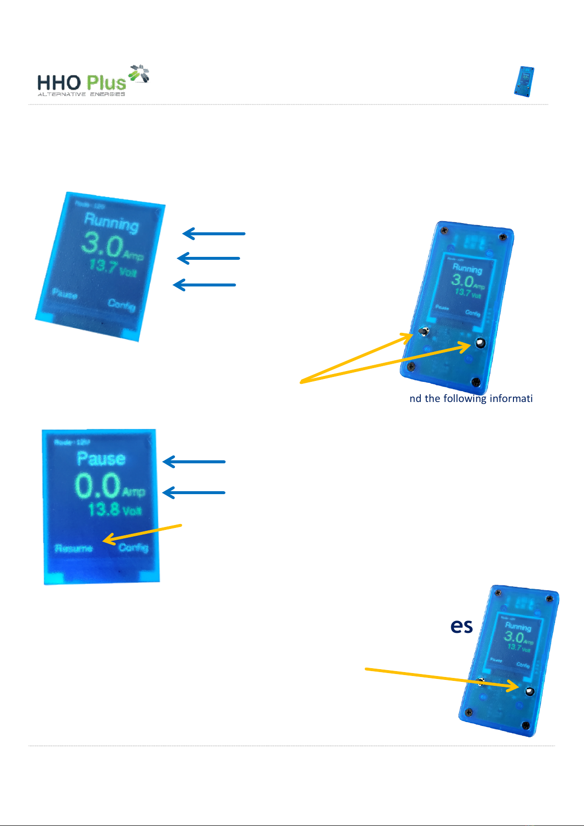
8 Front Panel
When you connect the CCPWM60A you will
In the CCPWM you have two buttons that will allow you
to change settings and
control the device operation.
For example: if you press the
left button (Pause)
will be presented:
If you press the
9
Configuration Panel.
If you press the
right button (Config)
you can change the operating values.
CCPWM60A –
Installation Manual
When you connect the CCPWM60A you will
have
the following information displayed:
In the CCPWM you have two buttons that will allow you
control the device operation.
left button (Pause)
then the CCPWM will pause and the following information
If you press the
left button again (Resume)
then the CCPWM will
Configuration Panel.
Setting the values
right button (Config)
you will enter the configuration display where
you can change the operating values.
Voltage in the Car
Amperage in the Dry-Cell
Operation Information
No amperage in the Dry-Cell
Pause information displayed
Installation Manual
7
the following information displayed:
then the CCPWM will pause and the following information
then the CCPWM will
restart.
Setting the values
you will enter the configuration display where
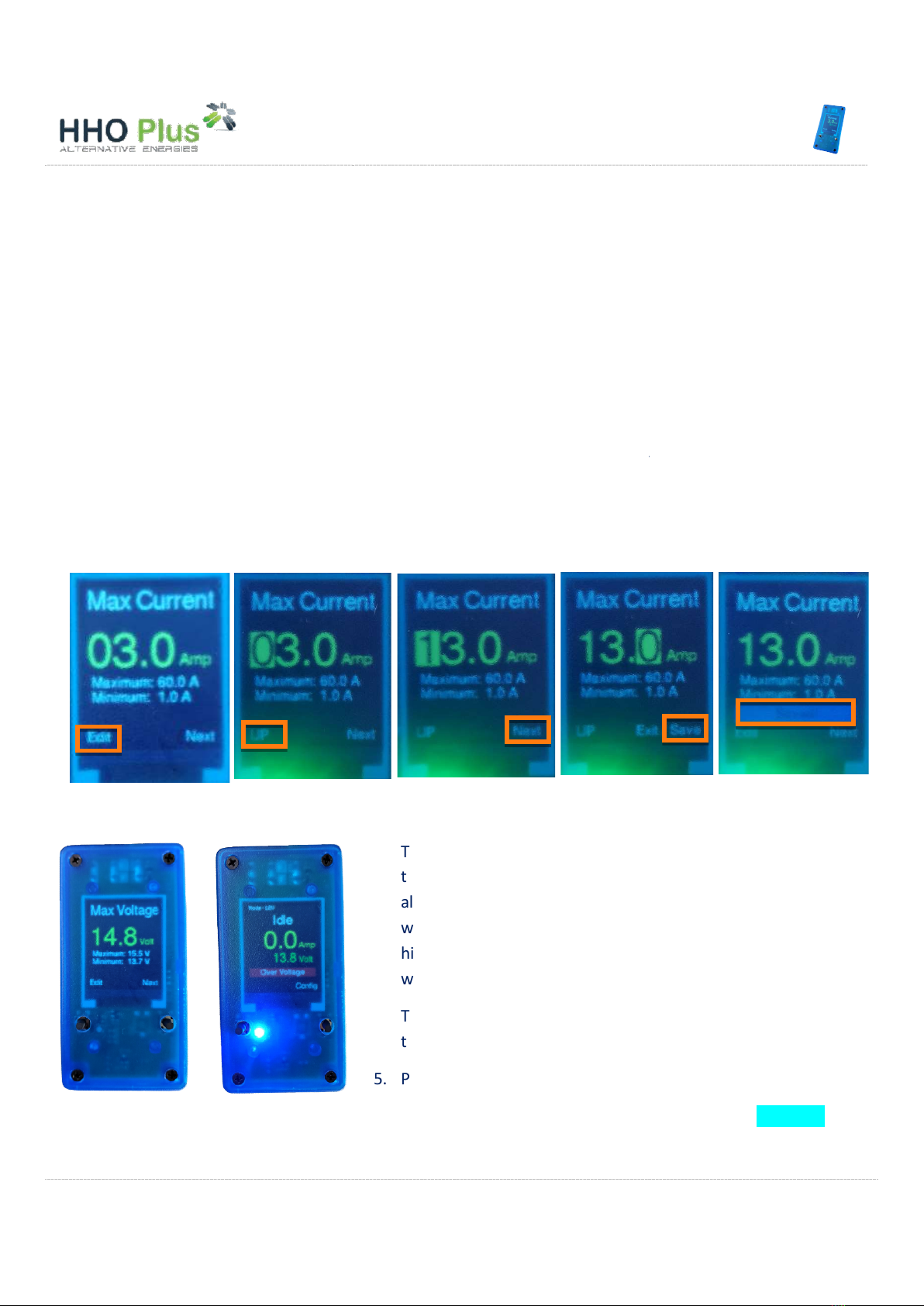
Amperage
The Maximum Current Panel
will appear for you to set the amperage value you wish to work:
Minimum 1 A / Maximum 60A
1. If you press the
left button (Edit)
the editing value;
2. Use the left button (UP)
again
3. Press the right button (Next)
4. Repeat points 2. And 3.
to continue editing. After, i
a.
If you make one single click on the
b.
If you click and hold right button for 3 seconds you will
Savedwill appear.
5. Press right button (Next) to
move to
.
Maximum Voltage
For security reasons (ex: charging the battery)
appear.
CCPWM60A –
Installation Manual
will appear for you to set the amperage value you wish to work:
left button (Edit)
you will enter the editing mode.
A yellow cursor will appear marking
again
to move up the value;
to change the yellow cursor position;
to continue editing. After, i
n the right button,
Exit/Save
If you make one single click on the
right button
you will exit configuration pan
If you click and hold right button for 3 seconds you will
Save
your configuration. A message
move to
Maximum Voltage Panel
The Maximum VoltagePanel
will appear
the higher voltage
value you wish to work
allowed is
15,5V.For security reasons (ex: charging the battery
with an external power supply), if the voltage in the car is
higher than the value selected th
en the CCPWM60A will stop
working and an alarm will appear.
To set this value just proceed in the same way as explained for
the setting the amperage.
5. Press right button (Next) to
move to
For security reasons (ex: charging the battery)
above 15,5
V the CCPWM will not work and a
Installation Manual
8
will appear for you to set the amperage value you wish to work:
A yellow cursor will appear marking
Exit/Save
will appear:
you will exit configuration pan
el (Exit);
your configuration. A message
will appear
in order for you to set
value you wish to work
. The maximum value
15,5V.For security reasons (ex: charging the battery
with an external power supply), if the voltage in the car is
en the CCPWM60A will stop
working and an alarm will appear.
To set this value just proceed in the same way as explained for
move to
Minimum Voltage Panel
V the CCPWM will not work and a
blue light will
Saved

Minimum Voltage
The CCPWM60A is designed for making the automatic power supply of the HHO System without the need for
relays or picking up the signal from the alternator/ignition key,
install. In general the new CCPWM60A will work based on the voltage of the car:
- Engine is stopped –
voltage in caris
- Engine is working –
voltage in caris
IMPORTANT:
After having selected your voltage working limits you should test it
to check if it works correctly in your car. Stop engine and check if the CCPWM
shuts down. Start engine and check if CCPWM turns ON.
10
Water Level Sensor
The water level should be placed in a way that, when the water
level is above the minimum value, the signal coming from the
CCPWM does not return to the CC
PWM. That is, the water level
circuit should operate as normally
company models,
the water level sensor should be placed
(please check last picture on this manual).
If you are not using a water level sensor in your system,
operation is required.
If the water le
vel drops below the minimum level then the
CCPWM will not work and a
CCPWM60A –
Installation Manual
The CCPWM60A is designed for making the automatic power supply of the HHO System without the need for
relays or picking up the signal from the alternator/ignition key,
making the system safer to use and easier to
install. In general the new CCPWM60A will work based on the voltage of the car:
voltage in caris
below 12,8V PWM =>is not working;
voltage in caris
above 13VPWM =>is working.
The CCPWM will only work when the real car voltage value is
between the minimum and the maximum working voltage
value.
The CCPWM60A will shut down completely if the voltage drops
below 12,8V. If the voltage in the car is lower than the value
sel
ected then the CCPWM60A will stop working and an alarm
will appear.
To set this value just proceed in the same way as explained for
the setting the amperage.
After having selected your voltage working limits you should test it
to check if it works correctly in your car. Stop engine and check if the CCPWM
shuts down. Start engine and check if CCPWM turns ON.
Water Level Sensor
The water level should be placed in a way that, when the water
level is above the minimum value, the signal coming from the
PWM. That is, the water level
circuit should operate as normally
open (NO). Using our
the water level sensor should be placed
up
(please check last picture on this manual).
If you are not using a water level sensor in your system,
no
vel drops below the minimum level then the
CCPWM will not work and a
red light will appear
Installation Manual
9
The CCPWM60A is designed for making the automatic power supply of the HHO System without the need for
making the system safer to use and easier to
The CCPWM will only work when the real car voltage value is
between the minimum and the maximum working voltage
The CCPWM60A will shut down completely if the voltage drops
below 12,8V. If the voltage in the car is lower than the value
ected then the CCPWM60A will stop working and an alarm
To set this value just proceed in the same way as explained for
After having selected your voltage working limits you should test it
to check if it works correctly in your car. Stop engine and check if the CCPWM

Reseller in Greece:
VAT Id. Number: 801590498
Headquarters:
1KLM Lagkadas-
Thessaloniki, Greece
PC: 57200
Email: info@smart
-
Telephone:
+30 2394020077
VAT Id. Number: 801590498
Thessaloniki, Greece
-
cover.gr
+30 2394020077
Other manuals for CCPWM60A
3
Table of contents
Other HHO Plus Automobile Accessories manuals


Popular Automobile Accessories manuals by other brands

FormFit
FormFit HD 9D18-4 installation instructions

U.S. General
U.S. General 95187 instruction sheet

Silvercrest
Silvercrest IAN 88638 user manual

M-Power
M-Power PMP2RS103 quick start guide

pro user
pro user DIAMANT SG3 operating instructions

Maxxair
Maxxair SKYMAXX 97500i Installation instructions, Information and Operating guide


Let's Go Aero
Let's Go Aero BLACK BOX Assembly, installation and operation instructions

Horn Tools
Horn Tools HVWTRL1RR02FIT Mounting instructions

MAXTOOLS
MAXTOOLS TR300 user manual

Let's Go Aero
Let's Go Aero H01465 quick start guide

TigerTough
TigerTough 182103 installation guide

TypeS
TypeS BT56485 Care & use instructions