Clayton Power 1012-50 User manual

G3 COMBI
MODEL:
1012-50, 1024-30, 1312-80, 1512-80, 1524-40, 2012-100, 2324-50
VERSION: 2.0
USER’S MANUAL
Clayton Power
Website: www.claytonpower.com


Table of content
1.0 System specification
Electrical specification inverter
Mechanical specifications
General features
a. Mechanical dimensions
Model: 1512-80 2012-100 2324-50
1.2 Mechanical dimensions
Model: 1012-50 1024-30 1312-80 1524-40
2.0 Installation
Environment
Mounting the device
2.1 DC cables
EMC
Recommended cable
Mounting DC cables
2.2 AC Mains cables
Recommended cable
2.3 Fusing
AC input
AC output
DC input / battery
3.0 Device layout
3.1 External connections
3.2 External wiring
3.3 Neutrik connector’s assembly
4.0 Accessories
5.0 Operating the device
Inverter section
Switch ON the inverter
Remote ON / OFF
Errors inverter
Charger section
Charge current adjust
Charge characteristic setup
Activate the charger
Charge power reduction
Boost charging
Top charging
Fully charged battery
Deactivate the charger
Errors charger
5.1 Load search mode
Activate load search mode
Deactivate load search mode
Remote used with load search function
5.2 Charge current setting
Recommended settings
Temperature compensation (NTC sensor)
5.3 Charging stages
Boost charge
Top charging
Battery Full (Float charge)
Maintenance current (Float charge)
6.0 LED code description
7.0 Batteries
Lead acid batteries
Lead acid battery types
Battery sizing
Installation
Batteries in serial
Batteries in parallel
7.1 Maintenance batteries
7.2 Battery storage
8.0 Warranty

Electrical Specification Inverter
MODEL 1012 1312 1512 2012 1024 1524 2324 2336
POWER RATING
Continuous output power FTS (Full Temperature Scale) 1000W 1300W 1500W 2000W 1000W 1500W 2300W 2300W
Output power surge ( 1 sec. ) 1800W 2800W 3000W 4000W 2000W 3000W 4000W 4000W
Output power surge ( 10 sec. ) 1300W 1700W 2000W 2800W 1500W 1800W 3000W 3000W
Output power surge ( 15 min. ) 1100W 1500W 1700W 2200W 1200W 1700W 2500W 2500W
Max. efficiency 90% 92% 90% 90% 93% 93% 92% 92%
CONSUMPTION
No load power consumption 10W 10W 15W 15W 10W 10W 15W 17W
Load search mode consumption <3W <3W <3W <3W <3W <3W <3W <3W
Sleep mode consumption <8mA <8mA <8mA <8mA <8mA <8mA <8mA <8mA
THERMAL MANAGEMENT
Max operating temperature 50°C 50°C 50°C 50°C 50°C 50°C 50°C 50°C
Min operating temperature (-20°C) (-20°C) (-20°C) (-20°C) (-20°C) (-20°C) (-20°C) (-20°C)
Max internal temperature (inverter shut down) 80°C 80°C 80°C 80°C 80°C 80°C 80°C 80°C
VOLTAGE OUT
Nominal output voltage 230 VAC 230 VAC 230 VAC 230 VAC 230 VAC 230 VAC 230 VAC 230 VAC
Output Voltage tolearance (-10%,+5%) (-10%,+5%) (-10%,+5%) (-10%,+5%) (-10%,+5%) (-10%,+5%) (-10%,+5%) (-10%,+5%)
Output Voltage tolearance (at input voltage 25V to 31.5V)
_ _ _ _ _ _ _ (-18%,+5%)
Frequency 50Hz 50Hz 50Hz 50Hz 50Hz 50Hz 50Hz 50Hz
Output wave form Sine Sine Sine Sine Sine Sine Sine Sine
THD max. 3% 3% 3% 3% 3% 3% 3% 3%
VOLTAGE IN
Battery input voltage (nominal) 12 VDC 12 VDC 12 VDC 12 VDC 24 VDC 24 VDC 24 VDC 36 VDC
Max input voltage 15 VDC 15 VDC 15 VDC 15 VDC 30 VDC 30 VDC 30 VDC 45 VDC
Low battery voltage cut-off (Slow reaction 3 Sec.) 10.5 VDC 10.5 VDC 10.5 VDC 10.5 VDC 21 VDC 21 VDC 21 VDC 25 VDC
Low battery voltage cut-off (Fast reaction <10mS) 9 VDC 9 VDC 9 VDC 9 VDC 18 VDC 18 VDC 18 VDC 23 VDC
Voltage before inverter can switch ON again (after a low battery cut-off) 12.75 VDC 12.75 VDC 12.75 VDC 12.75 VDC 25.5 VDC 25.5 VDC 25.5 VDC 38.25 VDC
Electrical Specification Charger
MODEL 1012-50 1312-80 1512-80 2012-100 1024-30 1524-40 2324-50
BATTERY
Battery types
Open &
Sealed Lead
acid
Open &
Sealed Lead
acid
Open &
Sealed Lead
acid
Open &
Sealed Lead
acid
Open &
Sealed Lead
acid
Open &
Sealed Lead
acid
Open &
Sealed Lead
acid
Charge characteristic IUoUo IUoUo IUoUo IUoUo IUoUo IUoUo IUoUo
Battery temperature sensor (NTC) Yes Yes Yes Yes Yes Yes Yes
CHARGE CURRENT
Max charge current (adjustable) 0 - 50A 0 - 80A 0 - 80A 0 - 100A 0 - 30A 0 - 40A 0 - 50A
Charge current reduction (% of max current) @ 50°C 0% 0% 0% 0% 0% 0% 0%
Charge current reduction (% of max current) @ 60°C 15% 15% 15% 15% 15% 15% 15%
Charge current reduction (% of max current) @ 80°C 50% 50% 50% 50% 50% 50% 50%
CHARGE VOLTAGE
Boost charge voltage (factory pre-set) 14.4 VDC 14.4 VDC 14.4 VDC 14.4 VDC 28.8 VDC 28.8 VDC 28.8 VDC
Float charge voltage (factory pre-set) 13.5 VDC 13.5 VDC 13.5 VDC 13.5 VDC 27 VDC 27 VDC 27 VDC
INPUT MAINS
AC Input voltage max
265 VAC 265 VAC 265 VAC 265 VAC 265 VAC 265 VAC 265 VAC
AC input voltage min (full charge current)
185 VAC 185 VAC 185 VAC 185 VAC 185 VAC 185 VAC 185 VAC
AC input voltage min (reduced charge current)
110 VAC 110 VAC 110 VAC 110 VAC 110 VAC 110 VAC 110 VAC
AC Inrush current (max) 50 A 50 A 50 A 50 A 50 A 50 A 50 A
Power consumption (max)
Frequency 45 Hz – 65 Hz 45 Hz – 65 Hz 45 Hz – 65 Hz 45 Hz – 65 Hz 45 Hz – 65 Hz 45 Hz – 65 Hz 45 Hz – 65 Hz
Cos ϕ / Power factor 0,9 0,9 0,9 0,9 0,9 0,9 0,9
Max. efficiency 90% 90% 90% 90% 90% 90% 90%
BYPASS CURRENT
Bypass current AC input to AC output (max) 10A 10A 10A 10A 10A 10A 10A
FUSE RATING
Fuse rating (max) 10AT 10AT 10AT 10AT 10AT 10AT 10AT
Mechanical specifications
Model 1012 1312 1512 2012 1024 1524 2324 2336
IP class IP20 IP20 IP20 IP20 IP20 IP20 IP20 IP20
Dimensions of cabinet [ L x W x H ] mm 299x198,2x116 299x198,2x116 376x198,2x116 376x198,2x116 299x198,2x116 299x198,2x116 376x198,2x116 376x198,2x116
Dimensions of cabinet incl. terminals [ L x W x H ] mm 334x198,2x116 334x198,2x116 412x198,2x116 412x198,2x116 334x198,2x116 334x198,2x116 412x198,2x116 412x198,2x116
Weight 6kg 6kg 7,5kg 7,5kg 6kg 6kg 7,5kg 7,5kg
General features
Model 1012 1312 1512 2012 1024 1524 2324 2336
Overload protection Yes Yes Yes Yes Yes Yes Yes Yes
Short circuit protection output Yes Yes Yes Yes Yes Yes Yes Yes
Over temperature shut down Yes Yes Yes Yes Yes Yes Yes Yes
High battery voltage shut down Yes Yes Yes Yes Yes Yes Yes Yes
Lauqered PCB Yes Yes Yes Yes Yes Yes Yes Yes
Temperature controlled FAN Yes Yes Yes Yes Yes Yes Yes Yes
Galvanic separation Yes Yes Yes Yes Yes Yes Yes Yes
Remote option Yes Yes Yes Yes Yes Yes Yes Yes
DATA (communication) Yes Yes Yes Yes Yes Yes Yes Yes
Status indication LED in front panel Yes Yes Yes Yes Yes Yes Yes Yes
Status LED (data, remote active) in DC input endplate Yes Yes Yes Yes Yes Yes Yes Yes
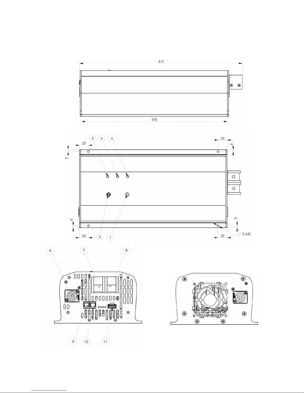
1.1 Mechanical Dimensions
Model: 1512-80 2012-100 2324-50

1.2 Mechanical Dimensions
Model: 1012-50 1024-30 1312-80 1524-40

2.0 Installation
Environment
• The inverter (or combi) must be placed in a dry, well ventilated and dust free location.
• Place the unit as close as possible to the battery in order to keep the battery cables as short as possible.
• Do not place the unit in same compartment as the batteries.
• Make sure that water or dust can not enter the cabinet.
• Ensure that the air flow from fan is not obstructed.
• Avoid mounting the device next to flammable materials.
Mounting the device
• The unit can be mounted on a wall, or flat mounted (4 x Ø5mm holes)
• Optimum cooling is obtained in vertical position.
• Make sure that each wire used in the installation has at least the same intersection and correct length, as
given in this manual!
• During wiring, use standard cable fixtures and wire ducts, do not bent extremely the cables/wires, and
avoid sharp edges to prevent the isolation of the wires/cables from cutting and abrasion.
• Keep in mind that usage of too long battery cables and dirty or loose connections may produce a
significant voltage drop which would cause that the device shut down for under voltage, even if the
battery is ok!
2.1 DC cables
EMC
• The wiring of the cables is influencing the EMC behavior of the system, in which the inverter is a
component. This is due to the fact that the cables are receiver and transmitter antennas of radio frequency
electromagnetic interference.
• Good EMC properties are obtained in the following way: Place the cables in a metal rail. The metal offers
resistance against interference currents. The battery cables should be placed close to each other to reduce
looping area. Cables from different groups should not be twisted, but be placed parallel with each other.
Recommended cable
• The table bellow is given by a criterion to keep the total cable voltage drop lower than 250mV at max
nominal power delivered by the combi.
Note: When starting up heavy load with high inrush current (compressors, motors, etc) it is
recommended to use cables with a even higher intersection (or shorter length) to prevent under-voltage
shut-down of the device
.
• The cable length (up to 3 meter) between the battery and the combi must be sized according to the table
below:
Note: Avoid cables longer than 3 meters between battery and combi!
Note: Cable length are defined per each cable (or as the distance between battery and combi)
mm2 AWG 1012-50 1312-80 1512-80 2012-100 1024-30 1524-40 2324-50
15 5 - - - - 1.5m - -
25 3 1.5m - - - 2.5m 1.5m -
35 2 2m 1.5m 1.5 - 3m 2.5m 1.5m
50 1/0 3m 2m 2m 1.5m - 3m 2m
70
2/0
-
3m
2.5m
2m
-
-
3m

Mounting DC cables
• PAY ATTENTION TO CORRECT POLARITY!
• Check that the battery voltage matches the DC input to the inverter (or combi).
• Check the battery poles are clean.
• Prepare good electrical contact, use brass or lead battery connectors at the battery poles.
• Connect only one cable at the time.
• Start with the Black cable (-). First connect to battery pole, then to inverter (or combi) (-) terminal
(black)
• Double check that Black (-) cable are connected to the correct terminals (-)
• Secure there is no risk of short circuit!
• Connect Red cable (+). First to battery pole, then to inverter (or combi) (+) terminal (red)
• When connecting the cables a spark will occur. Avoid sparks near the battery!
WARNING!
• Do not interchange the battery cables. It will result in instantaneous damage of the unit. Such
damage is not covered by the guarantee.
• Do not connect inverters (or combi) in parallel. It will damage the unit (s). Such damage is not
covered by the guarantee.
• Do not connect AC generator or AC mains to the unit’s AC output connector (grey Neutrik). It will
damage the unit. Such damage will not be covered by the guarantee.
2.2 AC Mains cables
• When installing the AC cables always refer to safety standards valid in your country!
• The use of RCD devices – also known as FI fail current protection is highly recommended in any
installation!
Recommended AC cable
• The table bellow gives the minimum recommended wire sizes of the mains cables!
• AWG 15 = 1.5mm2 AWG 17 = 1.0mm2
• The assembly of the mains connector is described in section 3.3 Neutrik connector’s assembly
1012-50 1024-30 1312-80 1512-80 1524-40 2012-100 2324-50
Mains Cable 17 AWG 17 AWG 15 AWG 15 AWG 15 AWG 15 AWG 15 AWG

3.0 Device layout
Auxiliary LED Description
Pos. Color Function
A Green
Lights when Data link is “High”
B Yellow Lights when Data link is “Low”
C Orange Lights when remote is ON
D Green Optional charger output 2
G3 COMBI Layout
Pos. Description
1. ON/OFF Power Switch
2. Potentiometer – Charging current
adjustment
3. Charger LED – Green
4. Inverter LED – Blue
5. Battery LED – Red
6. AC charger input connector, type
NEUTRIK ( Blue )
7. Positive voltage DC input terminal
8. Negative voltage DC input terminal
9. External DATA connector RJ12 type ( 6p6 )
10. External DATA connector RJ12 type ( 6p6 )
11. External DATA connector type PHOENIX
MSTBA 2,5/ 3-G-5,08
12. Fuse holder for input mains fuse
13. AC inverter output connector, type
NEUTRIK ( Grey )

Pin 1 Phoenix
Combicon
Pin 1
3.1 External connections
RJ12 type 6p6 connector: 1
Pin# Signal Description
1 - TEMPX1 Reserved for future use
2 User GND ( Fused )
3 + TEMPX1 Reserved for future use
4 SYNC_IN/OUT Used in option SYNC only
5 DATA Single Wire Clayton Communication
6 REMOTE
Connected to plus pole of the battery switches on the
combi.
Not connected = no influence
Phoenix Combicon MSTB 2.5 / 3-ST-5.08:
Pin# Signal Description
1 DATA Single Wire Clayton Communication
2 REMOTE
Connected to plus pole of the battery switches
on the combi
Not connected = no influence
3 CHG2_OUT Extra charger output ( option )2
1 The signal wires of the two connectors are connected parallel so the pin out and the signals on the corresponding pins are identical
2 Will be introduced and defined in future only in the case of Combi devices
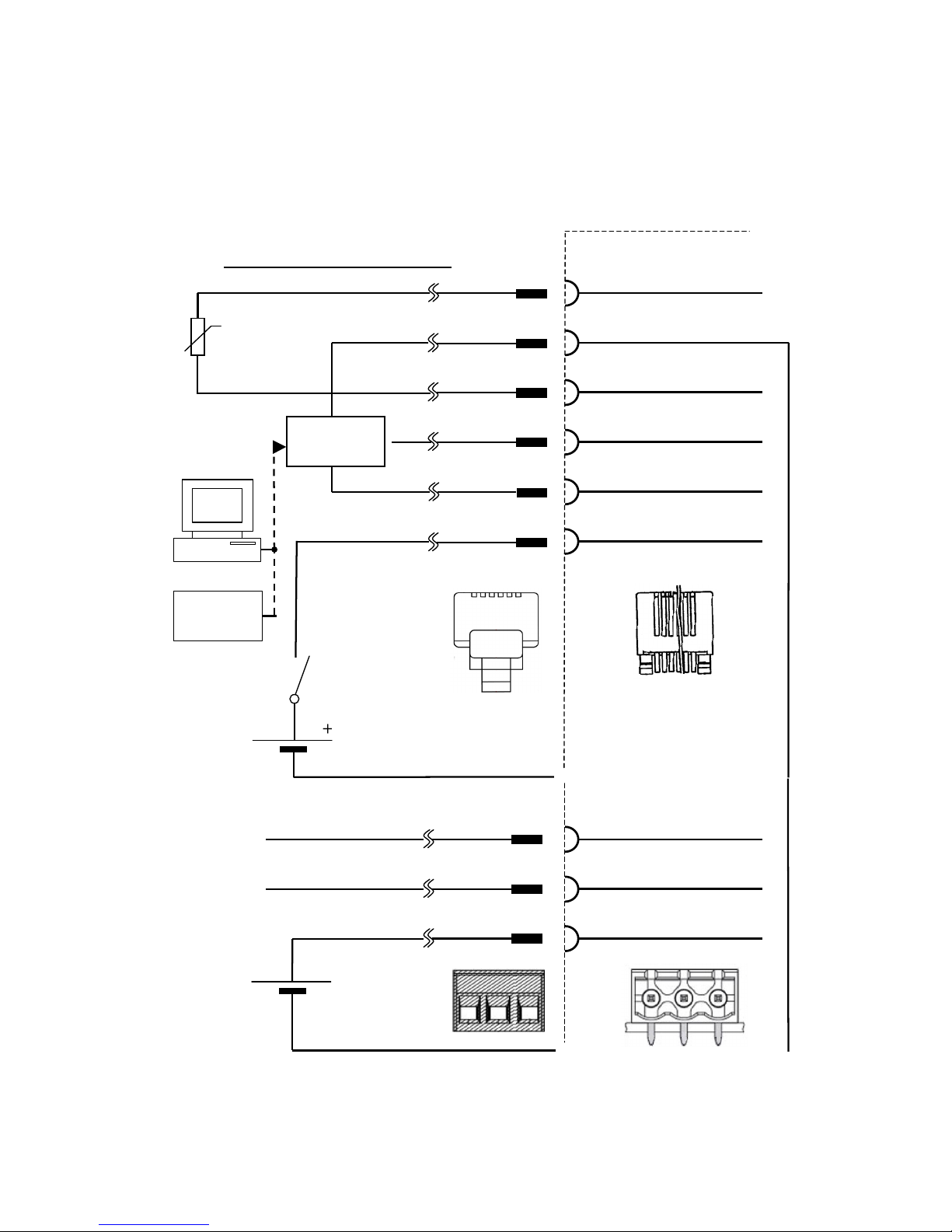
3.2 External Wiring
-TEMPX1
1
User GND
2
+TEMPX1
3
SYNC_IN/OUT
4
DATA
5
REMOTE
6
1
2
3
4
5
6
External NTC
Vishay
2381 640 63102
1K NTC
Single
Wire Bus
Clayton
Device
NC
+
Switch
( Relay, ignition …)
Modular plug
conforming to FCC
part 68, subpart F
Cable length maximum 3m!
Limit of the device
1
6
DATA
1
REMOTE
2
CHG2_OUT
3
1
2
3
1
3
1
3
See wiring above
See wiring above
+
Optional
Backup
Battery
The two RJ12 6 pole connectors are
connected parallel to each other pin to pin.
Phoenix-Contact
1757022

Housing Insert Chuck Bushing
3.3 Neutrik connectors assembly
Cable Preparation Wiring
Assembling
BLUE GREY
Combination for AC Power IN (only combi models) Combination for AC Power OUT
Engagement Separation

4.0 Accessories
5.0 Operating the device
•The aim of this section is to give a brief overview necessary to operate the device and give some proposal
how to solve most normal problems occurring during operation of the device.
Information for all LED error codes can be found in section 6.0 LED Code description.
Combi devices can operate in 3 modes:
Inverter mode
• Energy is taken from the battery, inverted to 230VAC delivered at output connector (grey Neutrik).
Charger mode
• The charger switch on automatically when a public grid or an AC generator (185-
265VAC) is present at the
AC input connector (blue Neutrik), a relay bypass the supplied AC voltage to the output (grey Neutrik). At the
same time some of the energy (from grid or generator) goes to recharge the battery bank.
Back up mode
• In case of black out of AC public grid, the device will switch over automatically to inverter function and the
connected equipment will still run powered by the battery.
• Important: the inverter section must be switched on!
Inverter section:
Switch ON the inverter
• Push down ON/OFF power switch for approximately. 2 seconds both blue and red LED will light.
• After 2 seconds red LED stops and the power switch can be released.
• The blue LED will flash to indicate start up sequence
• Blue LED lights and 230VAC is present.
Note: If the battery is discharged, then the red LED will continue to light, recharge battery and try again!
Note: The fan is running at full speed while the power supply is starting up for acoustic detection of the fan!
COMBI Accessories List
No. Description
a. AC output connector, type Neutrik NAC3FCB ( Grey )
b. Phoenix DATA connector: MSTB 2.5 / 3-ST-5.08 - Green
c. AC input connector , type Neutrik NAC3FCA ( Blue )

Charger section:
Charge current adjust
• The charge current can be adjusted by the potentiometer on the front panel top from 0A
up to maximum
rated charge current.
• See recommended charge current table in section 5.2 Charge Current Setting for correct adjustment.
Charge characteristic setup
• Future option!
Activate the charger
• The charger section will automatically switch on regardless of the ON/OFF power switch status, when 185-
265VAC is connected to the AC input (blue Neutrik)
Note: If the inverter is switched OFF, the charger will operate at even lower voltage than 185VAC,
down to
110VAC is in this mode is accepted But with reduced charge current!
Note: If AC was connected and then removed (short charge time), the inverter can be restarted even if the
battery is still empty!
Charge power reduction
• 2300W (10A) from the AC grid should not be exceeded! The charger reduces automatically the charge
current if the total power exceeds 2300W (charge power + load power)
Note: the regulation is slow in order to allow load peak currents, without disturbing the charging!
Important: The device has a build in fuse – see FUSING section -, do not exceed this limit!
Boost charging
• Fast flashing green LED, the charger delivers full charge current to the battery
Top charging
• Slow flashing green LED, the charge current is reduced in order not to exceed max battery voltage
allowed.
Fully charged battery
• Continuously light green LED
Deactivate the charger
• Remove AC, charging will stop.
Note: If the inverter was activated (ON) there will be 230VAC at the grey output connector (discharging)

Errors charger:
AC input voltage to low <185VAC (with inverter switched ON)
• 1 flash by green LED
Note: If the inverter is switched OFF, the charger will operate at even lower voltage than 185VAC,
down to
110VAC is in this mode is accepted But with reduced charge current!
AC input voltage to high >265VAC
• 2 flash by green LED (rear situation!)
AC input distortion
• The charger can not begin charging if the input voltage is a non sine wave, or heavily distorted!
• 1 flash by green LED
No NTC temperature sensor connected
• 4 flash by green + red LED together
Note: “No NTC connected” status is indicated every time the charger is connected to AC voltage (110VAC-
265VAC)
Note: “No NTC connected” flash code is only present for 20 seconds, and then the green LED will indicate
the actual charge status.
Note: If no NTC is used, the charger will charge the battery without temperature compensation!
Poor connections (or disconnection of battery during charging)
• 2 flash all LED together
Note: Always make sure that all connections joints are in a good quality: tighten all screws, wiring size must
be correct dimensioned, no corrosion at terminals etc.
WARNING!
Never disconnect cables during charging (and inverting) especially near the battery bank.
The battery can explode!
Defect battery
• The battery must be able to deliver min. 12W and min. 10,3V before charging can start!
Note: Never discharge a battery completely; it will cause permanent damage of the battery!
• No LED code for this error

5.1 Load search mode
• In cases where it is preferable to leave the combi switched on, and the load is periodically inactive
(switched OFF) the load search mode can be activated.
In this mode the combi is partly active and generate a short pulse every 2 second, if a load (>10W resistive)
is detected the device switch ON automatically. When a load is disconnected again the device automatically
returns to search mode (low consumption) after 1 min without load
• In load search mode the battery consumption is reduced to less than 3
W in order to save the battery during
no load periods!
Activate load search mode
• Switch OFF if the combi (if activated)
• Push down the power switch for > 5 seconds
• Release only when the blue, green and red LED starts to light at the same time.
Note: in load search mode the battery consumption is reduced, while no load is active! The device switch on
automatically when a load is connected (> 10W resistive)
The load search mode will remain active, until deactivation or disconnection of the battery (the mode will be
active > 15min after disconnecting the battery)
Note: there will be a small delay when connecting a load and until the device starts up automatically!
Note: If load search mode is entered with a load connected, the blue LED flashes slowly only
for 5 seconds
(to indicate entering of load search mode), then it lights continually!
Note: When a load has been connected and afterwards disconnected the device stays fully ON for 1 min
then it returns again to search mode (low battery consumption).
Deactivate load search mode
• Push power switch > 5 seconds.
• Release only when Blue, green and red LED start to flash at the same time.
Remote used with load search function
• The load search function will remain active if the device is switched ON and OFF by remote.
• Only deactivation (or disconnection of battery >15 min) will clear load search mode

5.2 Charge Current Setting
• Recommended battery capacity versus charging currents (at 20°C battery temperature)
Charge
Current
Recommended Battery
Capacity Range
15 A 75 – 150 Ah
20 A 100 – 200 Ah
25 A 100 – 250 Ah
30 A 150 – 300 Ah
40 A 200 – 400 Ah
50 A 250 – 500 Ah
60 A 300 – 600 Ah
80 A 400 – 800 Ah
120 A 600 – 1200 Ah
ATTENTION!
• If sealed lead acid batteries are overcharged it will result in gassing and dry-out and the battery will
be destroyed.
• Wet batteries (open type) will loose water and need to be topping up.
• If you are in doubt how your battery / batteries shall be charged please consult your Battery
Technical Manual (data sheet), or your local battery distributor.
Temperature compensation (NTC sensor)
• When using the external temperature sensor (NTC) the charger will reduce the charge current with respect
the max allowed battery voltage at the actual temperature!
• Refer to scheme: at 20°C the boost charge max voltage is 14,4V and float charge voltage 13,5V
• Use the NTC temperature sensor for optimal battery performance.

5.3 Charging Stages
• The charger is a fully automatic 3-stage charger with IUoUo characteristic.
Boost charge - Fast flashing green LED
• The charger will start in boost charge mode with max pre-set voltage and max charging current.
Top charging - Slow flashing green LED
• The battery has reached the maximum pre-set charging voltage and will automatically reduce the
charge
current until the charger measure 1Amp
Battery Full (Float charge) - Continuously light green LED
• The battery was detected fully charged.
Maintenance current (Float charge) - Continuously light green LED
• The charger keeps a pre-set float charge voltage, and adjusts the charge current automatically
to
compensate for battery discharging.
• The charger can deliver up to 50% (of max adjusted charger current) at float charge voltage.
• If the battery voltage drops below float charge voltage level, the charger switch over to boost charge mode.

6.0 LED codes description
• The Blue LED is for the Inverter section.
• Green LED is for the charger section.
• Red LED indicating the status of the battery.
• Two or all LED can also flash together; see description of the error / status!
Blue LED Description.
ON Inverter is running
1 Short flashes every 2. second Load search mode
1 Flash Inverter output is overloaded
2 Flash Inverter temperature is too high. (automatic cooling down and restart)
3 Flash Short circuit at inverter output
4 Flash Short circuit in power supply
5 Flash Overload in power supply while starting up
Green LED Description.
ON Battery fully charged – float charging
Slow flashing Charger is in absorption phase of charging (top charging)
Fast flashing Charger is boost charging
1 Flash Mains present but too low
2 Flash Mains too high
Red LED Description.
No light Battery okay
ON Battery voltage too low
Flashing Battery voltage too high
All LED Together Description.
ON Not used (reserved for future use)
Fast flashing Remote on and Power button on at the same time
1 Flash NTC error (internal temperature sensor)
2 Flash Over Voltage of internal high voltage DC link
3 Flash Half bridge failure
4 Flash Full bridge failure
Red and Green LED Together Description.
4 Flash
Temperature sensor (NTC) missing
This manual suits for next models
13
Table of contents
Other Clayton Power Inverter manuals


