TECO-Westinghouse Motor EV INVERTER Series User manual
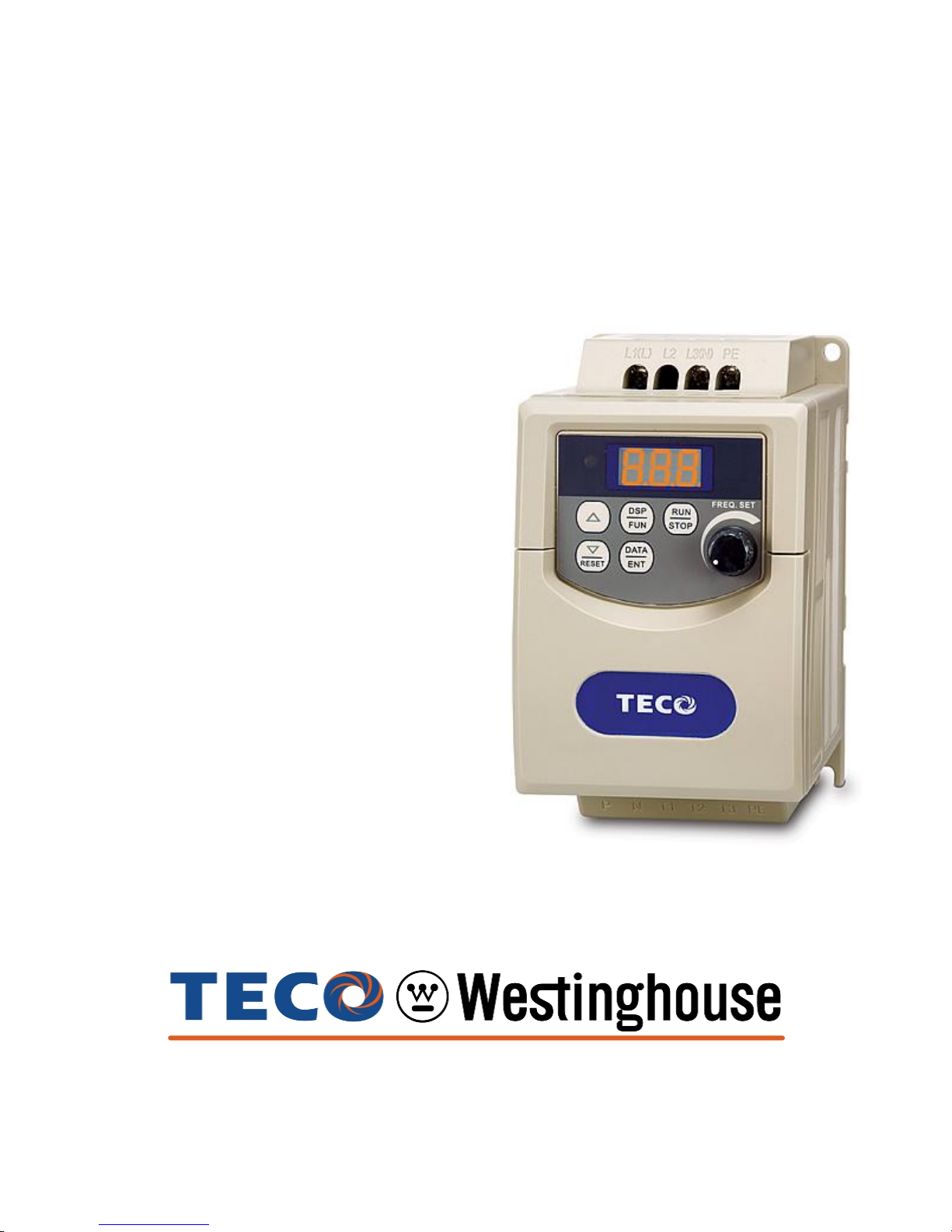
EV INVERTER SERIES
Operating Manual
110V 1Ø 0.2 - 1HP
0.2 –0.75kW
230V 1Ø /3Ø 0.2 - 3HP
0.2 –2.2kW
460V 3Ø 1 - 3HP
0.75 –2.2kW
Revision: 1.04.00

EV Inverter Operating Manual
___________________________________________________________________________
TECO –Westinghouse Motor Company 1
TABLE OF CONTENTS
Page
Introduction ……………………………………………………………………………….. 3
Section 1 Safety Precautions ………………………………………………………….. 3
1.1 Preface ………………………………………………………………….. 3
1.2 Receiving and Inspection ……………………………………………... 3
1.3 Installation and Pre-operation ………………………………………… 4
1.4 During Power ON ………………………………………………………. 4
Fig. 1 EV Pictorial Wiring Diagram ……………………………………………… 5
Section 2 Inverter Option Modules…………………………………………………… 6
Fig. 2.1 Option Card Installation and Wiring.................................. 6
Fig. 2.2 RS485 Interface (P/N SIF-485) .......………………………. 7
Fig. 2.3 RS232 Interface (P/N SIF-232) ……………………………. 7
Fig. 2.4 Copy Module (P/N SIF-MP) ……………………………….. 7
Fig. 2.5 Remote Keypad (P/N SDOP-LED-2M)............................. 8
Fig. 2.6 I/O Module (P/N SIF-IO)…………………………………….. 8
Fig. 2.7 PDA Link………………………………………………………. 8
Section 3 Control Signal Terminal Block Description…………………………… 9
Fig. 3.1 Control Terminals Designations…………………………… 9
Section 4 Input Power Terminal Block Description……………………………….10
Fig.4.1 Power Input Terminals Designations………………………… 10
Section 5 Output Power (Motor and Brake) Terminal Block Description…….. 10
Fig. 5.1 Power Output Terminals Designations……………………. 10
Section 6 Peripheral Power Devices………………………………………………… 11
Section 7 Fuse Types and Ratings………………………………………………….. 12
Section 8 Quick Start Guide………………………………………………………….. 13
Section 9 Keypad Key Functions and Navigation………………………………… 14
Fig. 9.1 EV Keypad
9.1 Key Functions………………………………………………………….…... 14
9.2 Keypad Navigation………………………………………………………… 15
Fig. 9.2.1 Basic Keypad Control………………………………………. 15
9.3 Local / Remote Function………………………………………………….. 15
9.4 Setting Parameters F (Basic) and C (Advanced)………………………. 16
Fig.9.4.1 Set F (Basic) and C (Advanced) Parameters……………… 16
Section 10 Parameters F (Basic) and C (Advanced)……………………………… 17
Table 10.1 F(Basic) Parameters……………………………………. 17 - 20
Table 10.2 C(Advanced) Parameters………………………………. 21 - 26
Section 11 Parameter Description (Basic) and C (Advanced)…………………. 27
Basic……………………………………………………………………… 27 - 42
Advanced………………………………………………………………… 43 - 53
Section 12 Envelope and Dimensional Tables…………………………………...... 54

EV Inverter Operating Manual
___________________________________________________________________________
TECO –Westinghouse Motor Company 2
Section 13 Error Codes and Troubleshooting……………………………………….. 55
Table 13.1 Unresettable / Unrecoverable Errors…………….............. 55
Table 13.2 Automatically and Manually Recoverable Errors………… 56
Table 13.3 Manually Recoverable Only Errors (No Auto Restart)…… 57
Table 13.4 Set-up Configuration and Interface Errors……………….. 57 - 58
Table 13.5 Keypad Errors ……………………………………………..… 58
Appendix A Inverter Specifications.......................................................................... 59
Inverter Basic Specifications................................................................. 59
Inverter General Specifications............................................................. 60 –62
Appendix B NEMA 4 Installation and Wiring............................................................ 63 –66
Appendix C Inverter Parameter Setting List........................................................... 67
Warranty……………………………………………………………………………………… 68

EV Inverter Operating Manual
___________________________________________________________________________
TECO –Westinghouse Motor Company 3
Introduction
The EV Inverter series is state of the art design using the latest control and power technologies.
It is designed to operate and control 3Ø induction motors in the range of 0.25 to 3hp and voltage
class of 230 or 460VAC. The inverter can operate either in V/ f or open loop vector mode settable
via programming. There are two sets of parameters, FBasic, and CAdvanced, allowing for
flexible control in many different applications. The membrane keypad in combination with a 3 digit
7 segment display allow for ease of programming and monitoring.
An optional communications module can be used for control and parameter setting using the
MODBUS RTU protocol. The EV has been designed with easy access to the input power, output
motor, and control terminals.
Before proceeding with the set-up and installation please take time to review this manual to
ensure proper operation and above all else, personnel safety.
SAFETY FIRST!
Section 1 - Safety Precautions
1.1 Preface
To ensure your safety and to avoid damage to the equipment,please read this manual
thoroughly before making any connections. Should there be any questions or problems in using
the product that cannot be resolved with the information provided in this manual, contact your
nearest representative for further guidance.
The inverter is an electrical product and as such, lethal voltages are present at various points. For
your safety, there are symbols as shown below that appear in this manual to remind you to pay
attention to safety instructions on handling, installing, and operating the inverter. Please follow the
instructions to insure the highest level of safety.
DANGER Indicates a potential hazard that could cause death or
serious personal Injury.
CAUTION Indicates that the inverter or the mechanical system might
be damaged.
Danger
After the power has been turned OFF, wait at least 5 minutes until the charge
indicator extinguishes completely before touching any wiring, circuit boards,
or components.
!1.2 Receiving and Inspection
Caution
All inverters have been tested for functionality prior to shipment. Please check the following
when you receive and unpack the inverter:
Check the nameplate to insure the model and capacity of the inverter are the same
as those specified in your purchase order.
Check for any damages as the result of transportation. If there is damage, do not
apply power, and immediately contact your representative.

EV Inverter Operating Manual
___________________________________________________________________________
TECO –Westinghouse Motor Company 4
1.3 Installation and Pre-operation
Caution
The inverter should be installed in a dry and dust-free area.
The inverter should be installed on a nonflammable surface such as metal.
The inverter may be operated up to an altitude of 1000m. Above 1000m it must be
de-rated. (Please consult factory)
If several inverters are to be placed in the same enclosure, additional cooling may be
needed to keep the surrounding temperature below 50°C to avoid overheating or
possible fire.
Do not connect T1, T2, and T3 terminals of the inverter to the AC power supply.
CMOS ICs on the inverter‘s main board are susceptible to static electricity. Do not
touch the main circuit board without proper precautions.
Do not perform dielectric tests on parts inside the inverter as the high voltage will
easily destroy semiconductor parts.
Wiring size and insulation type, as well as placement of the inverter, should conform
to applicable codes for a particular installation.
Control wiring should be kept separate from power wiring and cabling. In some
applications it may be necessary to use shielded cable for the control wiring and / or
the power cabling to avoid performance issues.
Danger
Do not modify any internal wiring, circuits, or parts. Connect the ground terminal of
the inverter properly. For 200V class Rg =< 100Ω, 400V class Rg =< 10Ω.
1.4 During Power ON
Caution
The display will flash the input voltage for about 2 seconds when power is applied.
Danger
To avoid damage to the control circuitry resulting from transient voltages, do not plug
or un-plug any connectors or connect or disconnect any wiring to or from the inverter
when power is present.
Do not change out parts and or check signals on circuit boards during the inverter
operation.
When power interruption to the inverter is momentary, the inverter has sufficient
power storage to ride through and continue operation. However, when power loss
interruption is longer than 2 seconds (the larger the horsepower, the longer the time);
the inverter does not have enough stored power to maintain control. Therefore, when
power is restored, the inverter restart is controlled as follows:
1 -Will not automatically run after restart if Run Command Source parameter
F04=000 keypad (Factory Default).
2 -Will not automatically run after restart if Run Command Source parameter
F04=001 external terminal (switch) is off.
3 -Will automatically run after restart if Run Command Source parameter
F04=001 external terminal (switch) is on and parameters F41=000. (Auto
Restart after power loss)
When removing or installing the keypad operator, turn OFF power first, and follow the
instruction diagram to avoid improper operation.

EV Inverter Operating Manual
___________________________________________________________________________
TECO –Westinghouse Motor Company 5
L1(L) PE
L3(N)
L2
19
3 4
2567810 11 12
100 –120VAC 1Ø
or
200 –240VAC 1Ø
200 –240VAC 3Ø
or
380 –480VAC 3Ø
INPUT POWER
Braking
Unit
+-
COM
S4
S3
S2
S1
+24V
RA
RB
Multi function
Relay Output
(
NO Contact
)
Source
Common point
(SW1 = PNP)
Sink
Common point
(SW1 = NPN)
+10V
AIN / S7
COM
FM+
Ain Multi function
Analog input
- Set Speed
PID Feedback
or
IM
Multi function
Analog output
(0 –10 Vdc)
NPN
PNP
V
SW1: Digital Signal Selection
(NPN
Sink
or PNP
Source
)
SW2 : Analog Control Selection
(V 0-10V; I 4-20 mA)
1
2
Connector 302
Option Plug –in Modules
Refer to Section 2
S7 Multi function
Digital input
I
NOTES:
1 - Digital inputs S1,S2,S3,S4, & S7 are
shown. Digital inputs
S5 & S6
are
provided with a plug-in option module
0V
P N T1 T2 T3 PE
Remove cover by squeezing
both sides and pulling up.
Fig. 1 EV Inverter Pictorial Wiring Diagram
Refer to Section 4 for additional
Input Power terminal
information
Refer to Section 5 for additional
Output Power terminal
information
Refer to Section 3 for additional
Control Signal terminal
information
(See Note 1))
Multi-functional
Digital Inputs

EV Inverter Operating Manual
___________________________________________________________________________
TECO –Westinghouse Motor Company 6
Section 2 - Option Modules
The following Option Modules are available for the EV Inverter series. They are easily
installed and are inserted into connector CON 302 by removing the front cover.
Caution - When installing option modules, make sure that power has been removed
from the inverter and that the charge indicator is extinguished before proceeding.
The front cover is removed by using finger pressure to push in on the sides of the
cover and lifting up. After the option module has been installed, replace the cover
before powering-up the inverter. Do not operate the inverter with the cover removed.
Option Part Number
Description
FIG. No.
SIF - 485
RS485 Interface
2.2
SIF - 232
RS232 Interface
2.3
SIF - MP
Copy Module
2.4
SDOP –LED –2M
Remote Keypad
2.5
SIF –IO
I/O Expansion
2.6
PDA Link
SIF - 232
RS232 Interface
2.7
JNSWPDA
PDA Cable Interface
Fig. 2.1 Option Card Installation and Wiring
Option Cards Plug into
Connector Con 302
(SIF-IO Module shown)

EV Inverter Operating Manual
___________________________________________________________________________
TECO –Westinghouse Motor Company 7
EV Inverter
Series
SIF-485
M
1Ø / 3Ø
Input Voltage
A
B
Red
Black
+24V
COM
RS485
+
-
Fig. 2.2 RS485 Interface P/N SIF-485
CON302
EV Inverter
Series
SIF-232
M
1Ø / 3Ø
Input Voltage
RS232
Fig. 2.3 RS232 Interface P/N SIF-232
CON302
EV Inverter
Series
SIF-MP
M
1Ø / 3Ø
Input Voltage
Fig. 2.4 Copy Module P/N SIF-MP
CON302
NOTE: Use isolated RS232 / RS485
converter connections between PC
and option card to avoid equipment
damage.
NOTE: Use isolated RS232 / RS485
converter connections between PC
and option card to avoid equipment
damage.

EV Inverter Operating Manual
___________________________________________________________________________
TECO –Westinghouse Motor Company 8
EV Inverter
Series
M
1Ø / 3Ø
Input Voltage
Red
Black +24V
COM
Fig. 2.5 Remote Keypad P/N SDOP-LED-2M
CON302
SDOP-LED-2M
24V
COM
A
B
EV Inverter
Series
SIF-IO
M
1Ø / 3Ø
Input Voltage
Red
Black +24V
COM
CON302
EV Inverter
Series
SIF-232
M
1Ø / 3Ø
Input Voltage
Fig. 2.7 PDA Link
CON302
Fig. 2.6 I/O Module P/N SIF- IO
P/N JNSWPDA
PDA Wire
HP iPAQ Pocket PC h2210. (PDA) / PC hx2190
RS232
S5: Digital Input
S6: Digital Input
T+:Photocoupler Output +
T-: Photocoupler Output -
Refer to the option manual for
additional details.

EV Inverter Operating Manual
___________________________________________________________________________
TECO –Westinghouse Motor Company 9
Section 3- Control Signal Terminal Block Description
RA RB 24V S1 S2 S3 S4 COM COM10V AIN/S7 FM+
1 2 3 4 8
5 6 7910 11 12
TM2
Fig. 3.1 Control Terminals Designations
Terminal
No.
Terminal
Designation
Description
1
RA
Multi –function digital output
NO contact rated 250V @ 10A
Refer to parameter F21 (000 –015) for selecting output functions
2
RB
3
24V
24VDC @ 20mA Max.
- Provides the common point for the multi –function digital inputs S1
–S4 when SW1 is set to PNP (Source Mode).
- Provides input power for the various option cards when required.
4
S1
Multi –function digital input terminals
Refer to parameters F11 –F14 (000 –016 ,019) for selecting input functions
5
S2
6
S3
7
S4
8
COM
Output common
- Provides a common for both the 10V (terminal 9) and 24V (terminal 3)
sources
- Provides the common point for the multi –function digital inputs S1 –S4
when SW1 is set to NPN (Sink Mode).
- Provides a common for various option cards
9
10V
10VDC @ 20mA Max.
- Reference voltage supply for an external speed control potentiometer.
10
AIN / S7
Analog or digital
- AIN Analog:When terminal 10 is used as an analog input refer to
parameters F15 (017 & 018), F16 (000-001), F17, F18, F19 (000-001)
and F20 (000-001).
- S7 Digital:When terminal 10 is used as a digital input, parameters
described for multi –function digital input terminals S1 –S4 apply.
NOTE : Logic level high; => +8V* logic level low level; =< 2V
*Caution! Do not exceed 10V maximum.
11
COM
Output common
- Same as terminal 8
12
FM+
Multi –function analog output
0 –+10VDC, Refer to parameter F26 (000-005) for output functions.

EV Inverter Operating Manual
___________________________________________________________________________
TECO –Westinghouse Motor Company 10
Section 4- Input Power Terminal Block Description
Fig. 4.1 Power Input Terminal Designations
L1(L) L2 L3(N) PE
Terminal
Designation
Description
L1(L)
Main power input :
(Single Phase) ( L) –(N) *(100 –120VAC or 200 –240VAC)
(Three Phase) L1 –L2 –L3 *(200 –240VAC or 380 –480VAC)
L2
L3(N)
PE
Earth Ground
*
Caution - *Refer to the inverter nameplate for input voltage specifications
Section 5 - Output Power (Motor and Brake) Terminal Block Description
P N T1 T2 T3 PE
Fig. 5.1 Power Output Terminal Designations
Terminal
Designation
Description
P
DC Power and braking unit
N
T1
Inverter power output (Motor connections)
*3Ø (Three Phase) 0 –200Hz Max.
T2
T3
PE
Earth ground
*
Caution - *Refer to the inverter nameplate for output voltage specifications

EV Inverter Operating Manual
___________________________________________________________________________
TECO –Westinghouse Motor Company 11
Section 6 - Peripheral Power Devices
The following describes some of the precautions that should be followed when selecting peripheral power
devices.
Induction
Motor
Power Supply
Molded
Circuit
Breaker
Magnetic
Contactor
AC Reactor
Input Noise
Filter
EV
Inverter
Output
Noise Filter
Fuse
E
or
Power supply:
Make sure the correct voltage is applied to avoid damaging the
inverter.
Molded-case circuit breaker (MCCB) or fused disconnect
A molded-case circuit breaker or fused disconnect must be installed
between the AC source and the inverter that conforms to the rated voltage
and current of the inverter to control the power and protect the inverter.
(See section 7 for fuse ratings)
Do not use the circuit breaker as the run/stop switch for the
inverter.
A suitable fuse should be installed with inverter rated voltage and current
when a MCCB is not being used. (Please refer to Sec.7 for
recommended current ratings)
Ground fault detector / breaker:
Install a ground fault breaker to prevent problems caused by current
leakage and to protect personnel. Select current range up to 200mA,
and action time up to 0.1 second to prevent high frequency failure.
Magnetic contactor:
Normal operations do not need a magnetic contactor. When performing
functions such as external control and auto restart after power failure, or
when using a brake controller, install a magnetic contactor.
Do not use the magnetic contactor as the run/stop switch for
the inverter.
AC line reactor for power quality:
When inverters are supplied by a high capacity (above 600KVA) power
source, an AC reactor can be connected to improve the power factor.
Input and output noise filter:
A filter must be installed when there are inductive loads affecting the
inverter.
Inverter:
Output terminals T1, T2, and T3 are connected to U, V, and W terminals
of the motor. If the motor runs in reverse while the inverter is set to run
forward, swap any two terminals connections for T1, T2, and T3.
To avoid damaging the inverter, do not connect the input terminals
T1, T2, and T3 to AC input power.
Connect the ground terminal properly.( 230V series: Rg <100;
460V series: Rg <10.)

EV Inverter Operating Manual
___________________________________________________________________________
TECO –Westinghouse Motor Company 12
Section 7 - Fuse Types and Ratings
Inverter input fuses are provided for safely disconnecting the inverter from the input power in the
event of a failure in the inverter‘s power circuitry. The inverter‘s electronic protection circuitry is
designed to clear inverter output short circuits and ground faults without blowing the inverter input
fuses. The table below shows the EV input fuse ratings; To protect the inverter most effectively,
use fuses with current-limiting capabilities.
RK5 and CC/T type fuse ratings for the EV AC Drive series
115V class (1Ø)
JNEV-
HP
KW
KVA
100% CONT
Output AMPS
Max.RK5
FUSE
Rating(A)
Max.CC or T
FUSE
Rating(A)
1P2-H1
0.25
0.2
0.53
1.7
10
20
1P5-H1
0.5
0.4
0.88
3.1
15
30
101-H1
1
0.75
1.6
4.2
20
40
230V class (1Ø)
JNEV-
HP
KW
KVA
100% CONT
Output AMPS
Max.RK5
FUSE
Rating(A)
Max.CC or T
FUSE
Rating(A)
2P2-H1
0.25
0.2
0.53
1.7
8
15
2P5-H1
0.5
0.4
0.88
3.1
10
20
201-H1
1
0.75
1.6
4.2
15
30
202-H1
2
1.5
2.9
7.5
20
40
203-H1
3
2.2
4.0
10.5
25
50
230V class (3Ø)
JNEV-
HP
KW
KVA
100% CONT
Output AMPS
(A)
Max.RK5
FUSE
Rating(A)
Max.CC or T
FUSE
Rating(A)
2P2-H3
0.25
0.2
0.53
1.7
5
8
2P5-H3
0.5
0.4
0.88
3.1
8
10
201-H3
1
0.75
1.6
4.2
12
15
202-H3
2
1.5
2.9
7.5
15
20
203-H3
3
2.2
4.0
10.5
20
30
460V class (3Ø)
JNEV-
HP
KW
KVA
100% CONT
Output AMPS
(A)
Max.RK5
FUSE
Rating(A)
Max.CC or T
FUSE
Rating(A)
401-H3
1
0.75
1.7
2.3
6
10
402-H3
2
1.5
2.9
3.8
10
15
403-H3
3
2.2
4.0
5.2
10
20
Note: Fuse ratings are based upon 300V fuses for 120V inverters, 300V fuses for
230V inverters, and 500V for 460V inverters.

EV Inverter Operating Manual
___________________________________________________________________________
TECO –Westinghouse Motor Company 13
Section 8 - Quick Start Guide
This guide is a step by step procedure to assist in installing and operating the inverter with a
motor to verify that they work properly. Starting, stopping, and motor speed will be initially
controlled from the keypad. After the initial check has been completed, the inverter may then be
configured for a particular application that may require external control or special systems
programming.
Step 1: Before starting the inverter
Safety First! Please refer to Section 1 Safety precautions, before proceeding.
Check inverter and motor nameplate to determine that they have the same HP and voltage
ratings. (Ensure that full load amps of the motor does not exceed that of the inverter.)
With power OFF, wire and verify that AC power is connected to L1(L), L2, and L3(N).
CAUTION - For single phase power, apply only to terminals L1(L) and L3(N)
Wire and verify that the motor leads are connected to T1, T2, and T3.
When using a braking module, connect the terminal voltage of the braking unit to (P+ and N–
) terminals on the inverter.
Step 2: Apply power to the inverter
Apply the appropriate AC power to the inverter and observe the keypad display. The 3 digit 7-
segment display should show the input power voltage for 3- 5 seconds and then show the
frequency command value of 05.0 (factory default). At this point the display will be blinking. The
Power ON Indicator LED should also be ON.
Step 3: Check motor rotations without load
On the keypad, press the RUN key. The display will be on steady and indicate 00.0 to 05.0,
which is the value of the inverter output frequency applied to the motor.
Verify the operation and direction of the motor. If the direction of the motor is incorrect, press
the STOP Key, and turn OFF the AC power. Before proceeding any further verify that the
Power Indicator LED on the inverter keypad is COMPLETELY OFF.
Swap the leads connected to the inverter T1 and T2 terminals. Go to Steps 2 and 3 and
recheck the motor direction.
Press the STOP key.
Step 4: Check motor full speeds at 50Hz/60Hz
On the keypad, change the inverter output frequency with the,arrows, and then press the
DATA/ENT key to store the new value. In this case set it to 60Hz.
Press the RUN /STOP key, and observe the motor operation as it accelerates to full speed.
Press the RUN/STOP key, and observe the motor operation as it decelerates to 0 speed.
After satisfying the above, you can proceed with setting the application specific parameters and
permanent installation.
Power
Indicator

EV Inverter Operating Manual
___________________________________________________________________________
TECO –Westinghouse Motor Company 14
Section 9 -Keypad Key Functions and Navigation
The EV keypad, Fig. 9.1,provides all the necessary functions to allow full control of the EV
inverter. The keypad has membrane type keys and a 7-segment 3-digit LED display. Also located
on the keypad is a potentiometer that can be used to control inverter output frequency when
selected as the control source. There is also an LED indicator which serves to show both power
on as well as a DC bus charge indicator when power is removed. A remote keypad is available
as an option, and is covered more in detail in the Option Modules (See section 2).
Output frequency
control potentiometer
(when selected)
3-digit 7-segment
LED display
Membrane keys
Power ON / charge
indicator LED
Fig. 9.1 EV Keypad
9.1 Key Functions
The keys are multifunctional, providing for both control of the inverter when keypad mode is
selected (Default) and access in setting various parameters. The key functions are as follows.
RESET UP / DOWN(Reset)
· Sets the inverter output frequency in increments of
0.1Hz
when using
the keypad mode.
· Scrolls through the Fand Cparameters.
·Reset: Resets the inverter after a
Fault
has been cleared.
RUN
STOP RUN / STOP
· Controls the output of the inverter when selected in the keypad mode. It is an
on / off
toggle function.
DSP
FUN DISPLAY / FUNCTION
· Toggles the display between the inverter output selected values (Hz etc.) and the F
and Cparameter list.
DATA
ENT DATA / ENTER
· In conjunction with the
DSP / FUN
key allows selection of the
function
or
value
of
the various parameters with the
UP / DOWN
keys and to
save
updated parameter
settings.
· Used in conjunction with the DOWN / RESET key to toggle between
Local
and
Remote
operation.

EV Inverter Operating Manual
___________________________________________________________________________
TECO –Westinghouse Motor Company 15
9.2 Keypad Navigation
When attempting to control and set various parameters for the inverter it would be useful for the
user to become familiar with keypad navigation and to go through a few function changes before
making the final settings.
9.2.1 Basic Keypad Control (Factory Default, F04=000 & F05=000) Fig. 9.2.1
In its basic form as received from the factory, the inverter output is controlled from the keypad.
Please refer to the Fand Cparameter list (Sec. 10) to view the factory default settings for the
various parameters. When the inverter is powered up, the display will be flashing and
momentarily show the inverter input voltage. The display will then switch to a minimum output
frequency of 05.0Hz. By pressing the RUN / STOP key the output is active (RUN) and the display
is on solid. Using the UP / DOWN keys, the output frequency may be set in increments of 00.1Hz
from 00.0 to 50.0/60.0Hz. This can be done when the inverter is in the RUN or STOP mode.
When the
RUN / STOP key is toggled to STOP, the set frequency is displayed and the display is again
flashing. The Down key also functions to initiate a RESET after a Fault is cleared.
RUN
STOP
Initial power-up
RESET
Input voltage
(VAC)
Display
flashing
Initial output
frequency (Hz)
Display flashing
in STOP mode
Up Down
Output frequency control
0 –50/60 Hz in 0.1Hz
increments
Display steady
in RUN mode
Fig. 9.2.1 Basic Keypad Control
Apprx. 2 sec.
Reset after
fault clear
9.3 Local / Remote Function
In Local mode:
The RUN command is controlled by the RUN / STOP key.
Frequency command
-If C41= 000: The UP / DOWN keys control the output
frequency.
-If C41= 001: The front panel potentiometer controls the output
frequency.
In Remote mode:
The RUN command is controlled via the function set by (F04)
The frequency command is set by the function set by (F05)
To toggle between Local / Remote press the keys simultaneously.
DATA
ENT RESET
RESET
RUN
STOP

EV Inverter Operating Manual
___________________________________________________________________________
TECO –Westinghouse Motor Company 16
9.4 Setting Parameters F(Basic) and C(Advanced) Fig. 9.4.1
The basic parameters Fcan be accessed in two ways; via the keypad or through the MODBUS
protocol using an optional communications module. Here we will describe keypad access. Before
proceeding, refer to the Fand Cparameter lists (Sec. 10) and note that some parameters must be
changed with the inverter in the STOP mode while others can be changed in either the RUN or STOP
mode. Also, changing certain parameters may affect other functions and should be carefully
considered before making those changes.
To enter the Fparameters, press the DSP / FUN key; the display should show F00. Using the Λ / V
keys, select the parameter to set and then press the DATA / ENT key. The display should be showing
the existing code or function for that parameter. Using the Λ / V keys, select the desired code or
function and then press the DATA / ENT key to save; the display should momentarily flash End and
return to the Fmenu. To enter the C(advanced) parameters select F51 and then Code = 001; C00
will be displayed. Using the same procedure in setting the Fparameters scroll to the desired C
parameter and select the code or function to be set and then press the DATA / ENT key to save. To
return to the F parameter list press the DSP / FUN key twice and set F51 to Code = 000. After all
parameter changes have been made, press the DSP / FUN key to return the display show the output
frequency.
DATA
ENT
DSP
FUN
RESET
Scroll from
F00 to F54
Fparameters
displayed
Scroll to function
or code
DATA
ENT
Display
flashing
Parameter
function or value
saved
Toggles display between
the set output frequency
and F parameters
To enter the
Advanced
parameters, select
F51 and then 001
Don’t forget to save
DSP
FUN
Advanced
parameters
displayed
DATA
ENT
Scroll to function
or code
DATA
ENT
Display
flashing
Parameter
function or value
saved
RESET
Scroll from
C00 to C55
To return to F
parameters
DSP
FUN
Toggle twice
Set F51=000
Returns to Advanced menu
Returns to F menu
Fig. 9.4.1 Set F (Basic) and C (Advanced) Parameters

EV Inverter Operating Manual
___________________________________________________________________________
TECO –Westinghouse Motor Company 17
Section 10 -Parameters F (Basic) and C (Advanced) Function Tables
Overview –The EV Inverter Series is program capable to allow for a variety of application
requirements. The parameters are split into two categories, Fand C. The Fparameters set the
Basic functions of the inverter while the Cparameters control the more Advanced functions.
The parameters can be accessed and changed through the keypad. (Refer to Sec.9 for keypad
functions and navigation). They may also be accessed and changed though MODBUS protocol in
conjunction with an optional communications module (Refer to Sec. 2 for available
communication options).
When the inverter is shipped from the factory each parameter is set at a Factory Default value
and is so specified in the Tables. Most parameters may not be changed when the inverter is in
the RUN mode. Those parameters that can be are so noted (note 1) in the Remarks column.
Table 10.1 F (Basic) Parameters
F
Parameter
Code
Range/ Function
Factory
Default
Remarks
F00
Inverter horsepower capacity
code
-
Note 5
F01
Acceleration time 1 (sec.)
-
00.1 –999
05.0
Note 1 & 2
F02
Deceleration time 1 (sec.)
-
00.1 –999
05.0
Note 1 & 2
F03
Motor rotation direction
000
Forward
000
Note 1
001
Reverse
F04
Run command source
000
Keypad
000
001
External terminal
002
Communication control
F05
Frequency command
source
000
UP/Down key on keypad
000
001
Potentiometer on keypad
002
AIN (input signal from TM2)
003
Multi-function input terminal
UP/DOWN function
004
RS-485 Communication
frequency setting
F06
External control operation
mode
000
Forward / Stop -
Reverse / Stop
000
001
Run / Stop-
Forward / Reverse
002
3-wire—Run / Stop
F07
Frequency upper limit (Hz)
-
01.0 - 200
50.0 / 60.0
Note 2 & 7
F08
Frequency lower limit (Hz)
-
00.0 - 200
00.0
Note 2

EV Inverter Operating Manual
___________________________________________________________________________
TECO –Westinghouse Motor Company 18
F09
Stopping method
000
Decelerate to stop
000
001
Coast to stop
F10
Status display parameters
000
Disable
000
Note 1
001
Enable
F11
F12
F13
F14
F15
Terminal S1 function
Terminal S2 function
Terminal S3 function
Terminal S4 function
AIN –Can be set as an
analog input (017 Factory
default or 018) or as a digital
input and becomes S7
Note:
Digital inputs S1 –S4, *S5 and
S6 and S7 can be
programmed with Codes 000 –
016 and 019 only. Codes 017
and 018 are reserved for when
AIN is used as an analog input
*Digital Inputs S5 & S6 are
provided by an optional I/O
Module SIF-IO. ( see Sec.,
Fig. 2.6)
000
Forward
S1 = 000
S2 = 001
S3 = 005
S4 = 006
AIN = 017
001
Reverse
002
Preset speed command 1
003
Preset speed command 2
004
Preset speed command 3
005
Jog frequency command
006
Emergency stop (E.S.)
007
Base block (b.b.)
008
Select 2nd acceleration /
deceleration time
009
Reset
010
Up command
011
Down command
012
Control signal switch
013
Communication control
signal switch
014
Acceleration / deceleration
prohibit
015
Master / Auxiliary speed
source select
016
PID function disable
017
Analog signal input
(terminal AIN)
018
PID feedback signal
(terminal AIN)
019
DC Injection brake signal
*F16
AIN signal select
000
0-10V (0-20mA)
000
001
2-10V( 4-20mA)
*F17
AIN gain (%)
-
000 –200
100
Note 1
*F18
AIN bias (%)
-
000 –100
000
*F19
AIN bias
000
Positive
000
001
Negative
*F20
AIN slope direction
000
Positive
000
001
Negative
* Parameters F16 –F20 are used when F15 is selected as an analog input 017 or 018

EV Inverter Operating Manual
___________________________________________________________________________
TECO –Westinghouse Motor Company 19
F21
Multi-function output RY1
000
Run
000
001
Frequency reached
(Set frequency ± F23)
002
Frequency is within the
range set by (F22±F23)
003
Frequency detection
(>F22)
004
Frequency detection
(<F22)
005
Fault terminal
006
Auto reset and restart
007
Momentary power loss
008
Emergency stop (E.S.)
009
Base block (b.b.)
010
Motor overload protection
011
Inverter overload protection
012
Not used
013
Power on
014
Communication error
015
Output current
detection(>F24)
F22
Preset output frequency target
(Hz)
-
00.0 –200
00.0
Note 1
F23
Target frequency
detection range (±Hz)
-
00.0 - 30.0
00.0
Note 1
F24
Output current target value (%)
-
000 –100
000
F25
Output current detection
time(sec.)
-
00.0 –25.5
00.0
F26
Multi-function analog output
type selection
(0 - 10VDC)
000
Output frequency
000
Note 1
001
Set frequency
002
Output voltage
003
DC voltage
004
Output current
005
PID feedback signal
F27
Multi-function analog output
gain (%)
-
000 –200
100
Note 1
F28
Preset frequency 1 (Main
frequency setting) (Hz)
-
00.0 - 200
05.0
Note 1&2
F29
Preset frequency 2 (Hz)
-
00.0 - 200
05.0
Note 1&2
F30
Preset frequency 3 (Hz)
-
00.0 - 200
10.0
Note 1&2
F31
Preset frequency 4 (Hz)
-
00.0 - 200
20.0
Note 1&2
F32
Preset frequency 5 (Hz)
-
00.0 - 200
30.0
Note 1&2
F33
Preset frequency 6 (Hz)
-
00.0 - 200
40.0
Note 1&2
F34
Preset frequency 7 (Hz)
-
00.0 - 200
50.0
Note 1&2
F35
Preset frequency 8 (Hz)
-
00.0 –200
60.0
Note 1&2
F36
Jog frequency setting (Hz)
-
00.0 –200
05.0
Note 1&2
This manual suits for next models
16
Table of contents
Other TECO-Westinghouse Motor Inverter manuals