Clear One AP10 User manual
AP10 Telephone Interface
Installation & Operation Manual

ii
Technical Services Group ~ 1-800-283-5936 (USA) ~ 1-801-974-3760
© 2002 ClearOne Communications, Inc. All
rights reserved. No part of this document may
be reproduced in any form or by any means
without written permission from ClearOne
Communications, Inc. Printed in the United
States of America. ClearOne Communications
reserves specific privileges. Information in this
document is subject to change without notice.
AP10 Installation and Operation
Manual
ClearOne Part No. 800-150-201
June 2002 (Rev. 2.0)

iii
AP10 Installation and Operation Manual
Table of Contents
CHAPTER 1: Introduction . . . . . . . . . . . . . . . . . . . . . . . .1
Features . . . . . . . . . . . . . . . . . . . . . . . . . . . . . . . . . . . . . . . . . . . . . . . . .1
Professional Services Group . . . . . . . . . . . . . . . . . . . . . . . . . . . . . . . . . . .2
Product registration . . . . . . . . . . . . . . . . . . . . . . . . . . . . . . . . . . . .2
Product returns . . . . . . . . . . . . . . . . . . . . . . . . . . . . . . . . . . . . . . . . .2
Unpacking . . . . . . . . . . . . . . . . . . . . . . . . . . . . . . . . . . . . . . . . . . . . . . . .3
Controls and Connections . . . . . . . . . . . . . . . . . . . . . . . . . . . . . . . . . . . . .3
Front view . . . . . . . . . . . . . . . . . . . . . . . . . . . . . . . . . . . . . . . . . .3
Rear view . . . . . . . . . . . . . . . . . . . . . . . . . . . . . . . . . . . . . . . . . . .4
Before You Install . . . . . . . . . . . . . . . . . . . . . . . . . . . . . . . . . . . . . . . . . . .5
Power requirements . . . . . . . . . . . . . . . . . . . . . . . . . . . . . . . . . . . .5
Telephone line requirements . . . . . . . . . . . . . . . . . . . . . . . . . . . . . .5
Equipment placement . . . . . . . . . . . . . . . . . . . . . . . . . . . . . . . . . . .5
Environmental requirements . . . . . . . . . . . . . . . . . . . . . . . . . . . . . .5
CHAPTER 2: Installation . . . . . . . . . . . . . . . . . . . . . . . . . .7
Hardware Setup . . . . . . . . . . . . . . . . . . . . . . . . . . . . . . . . . . . . . . . . . . . .7
Connect the unit . . . . . . . . . . . . . . . . . . . . . . . . . . . . . . . . . . . . . .7
Creating a G-Link network . . . . . . . . . . . . . . . . . . . . . . . . . . . . . . .8
Assigning device ID numbers . . . . . . . . . . . . . . . . . . . . . . . . . . . . .9
Connecting power . . . . . . . . . . . . . . . . . . . . . . . . . . . . . . . . . . . . .10
CHAPTER 3: Configuration . . . . . . . . . . . . . . . . . . . . . . . .11
DIP Switch Settings . . . . . . . . . . . . . . . . . . . . . . . . . . . . . . . . . . . . . . . . .11
Noise Burst/Auto-Adapt . . . . . . . . . . . . . . . . . . . . . . . . . . . . . . . . .11
Receive Boost . . . . . . . . . . . . . . . . . . . . . . . . . . . . . . . . . . . . . . . .11
Receive AGC . . . . . . . . . . . . . . . . . . . . . . . . . . . . . . . . . . . . . . . . .12
Auto-Answer . . . . . . . . . . . . . . . . . . . . . . . . . . . . . . . . . . . . . . . . .12
Auto-Disconnect . . . . . . . . . . . . . . . . . . . . . . . . . . . . . . . . . . . . . .12
Call Progression/Loop . . . . . . . . . . . . . . . . . . . . . . . . . . . . . . . . . .12
Technical Services Group ~ 1-800-283-5936 (USA) ~ 1-801-974-3760

iv
Technical Services Group ~ 1-800-283-5936 (USA) ~ 1-801-974-3760
Receive Reduction . . . . . . . . . . . . . . . . . . . . . . . . . . . . . . . . . . . . .13
Calibration . . . . . . . . . . . . . . . . . . . . . . . . . . . . . . . . . . . . . . . . . . . . . . . .13
Noise Burst Adapt . . . . . . . . . . . . . . . . . . . . . . . . . . . . . . . . . . . . .13
Auto-Adapt . . . . . . . . . . . . . . . . . . . . . . . . . . . . . . . . . . . . . . . . . .14
Transmit level adjustment . . . . . . . . . . . . . . . . . . . . . . . . . . . . . . . .14
Receive level adjustment . . . . . . . . . . . . . . . . . . . . . . . . . . . . . . . . .14
CHAPTER 4: Operation . . . . . . . . . . . . . . . . . . . . . . . . . .15
Using the AP10 . . . . . . . . . . . . . . . . . . . . . . . . . . . . . . . . . . . . . . . . . . . .15
To answer a call . . . . . . . . . . . . . . . . . . . . . . . . . . . . . . . . . . . . . .15
To make and disconnect a call . . . . . . . . . . . . . . . . . . . . . . . . . . . . .15
Using the Telco Interface . . . . . . . . . . . . . . . . . . . . . . . . . . . . . . . . . . . . .16
To make and disconnect a call . . . . . . . . . . . . . . . . . . . . . . . . . . . . .16
To mute . . . . . . . . . . . . . . . . . . . . . . . . . . . . . . . . . . . . . . . . . . . .17
Other telco options . . . . . . . . . . . . . . . . . . . . . . . . . . . . . . . . . . . . .17
Controllers . . . . . . . . . . . . . . . . . . . . . . . . . . . . . . . . . . . . . . . . . . . . . . . .17
Custom control through DB-25 port . . . . . . . . . . . . . . . . . . . . . . . .17
Touch panel control . . . . . . . . . . . . . . . . . . . . . . . . . . . . . . . . . . . .17
APPENDICES . . . . . . . . . . . . . . . . . . . . . . . . . . . . . . . . .19
Appendix A: Specifications . . . . . . . . . . . . . . . . . . . . . . . . . . . . . . . . . . . .19
Appendix B: Pinouts . . . . . . . . . . . . . . . . . . . . . . . . . . . . . . . . . . . . . . . . .20
Appendix C: Serial Commands . . . . . . . . . . . . . . . . . . . . . . . . . . . . . . . . .21
Appendix D: Warranty . . . . . . . . . . . . . . . . . . . . . . . . . . . . . . . . . . . . . . .28
Appendix E: Compliance . . . . . . . . . . . . . . . . . . . . . . . . . . . . . . . . . . . . . .30
Appendix F: Block Diagram . . . . . . . . . . . . . . . . . . . . . . . . . . . . . . . . . . .32
Glossary . . . . . . . . . . . . . . . . . . . . . . . . . . . . . . . . . . . . . . . . . . . . . . . . .33
Index . . . . . . . . . . . . . . . . . . . . . . . . . . . . . . . . . . . . . . . . . . . . . . . . . . . .35

Technical Services Group ~ 1-800-283-5936 (USA) ~ 1-801-974-3760
CHAPTER 1: Introduction
Congratulations on purchasing the Audio Perfect
®
telephone interface. The AP10
uses advanced digital technology to maintain the highest possible audio quality. The
AP10 is designed as an accessory to the AP800 (echo cancelling, audio processing,
microphone mixing matrix) and enables the AP800 to connect to a standard
telephone line.
The AP10 is a single-line digital hybrid which uses digital signal processing
(DSP) to separate the transmit and receive audio—eliminating distortion, weak
signals, and feedback. It continually filters low and high frequency noise to provide
pure sound.
• Easy to install and operate
• DTMF dialing capability
• Simultaneous two-wire/four-wire operation within an Audio Perfect
system
• G-Link network interconnection with up to eight AP800s and 16 AP10s
• 9.6kHz sampling rate allows continual adaptation to telephone-line
conditions
• Full-time telco echo cancellation with 26 millisecond tail time
• Conference up to 16 callers (with 16 AP10s) within an Audio Perfect system
• Digital anti-alias filter minimizes hum and Central Office switching noise
• Remote On/Off control via serial commands or rear-panel connection
• Digital send filter/limiter for telephone line noise reduction
• Compatible with any analog telephone system
• No outside RF interference will affect performance
Features

Introduction ~ Unpacking
Technical Services Group ~ 1-800-283-5936 (USA) ~ 1-801-974-3760
2
If you need additional information on how to install, set up, or operate your system,
please contact us at one of the locations listed below. We welcome and encourage
your comments so we can continue to improve our products and serve your needs.
ClearOne Communications ~ 1825 Research Way ~ Salt Lake City, UT 84119
Technical Support
Telephone: 1.800.283.5936 (USA) or 1.801.974.3760
Fax: 1.801.977.0087
E-mail: [email protected]
Web site: www.clearone.com
Sales and Customer Service
Telephone: 1.800.945.7730 (USA) or 1.801.975.7200
Fax: 1.800.933.5107 (USA) or 1.801.977.0087
E-mail: [email protected]
ClearOne Communications EuMEA GmbH
Leonhardstr. 16-18, D-90443 Nuremberg, Germany
Telephone: +49 911 955159-0
Fax: +49 911 955159-10
E-mail: [email protected]
Product registration
Please register your AP10 online by visiting ClearOne Technical Support at
www.clearone.com
. When your product is properly registered, ClearOne
Communications is better able to serve you should you require technical assistance.
Registration information is also used to notify you of upgrades and new product
information.
Product returns
All product returns require a return authorization (RA) number. Please contact the
Technical Services Group before attempting to return your AP10 unit.
Professional Services Group
3
Introduction ~ Controls and Connections
Technical Services Group ~ 1-800-283-5936 (USA) ~ 1-801-974-3760
ClearOne is not responsible
for product damage
incurred during shipment.
You must make claims directly with
the carrier. Inspect your shipment
carefully for obvious signs of
damage. If the shipment appears to
be damaged, retain the original
boxes and packing material for
inspection by the carrier. Contact
your carrier immediately.
Unpacking
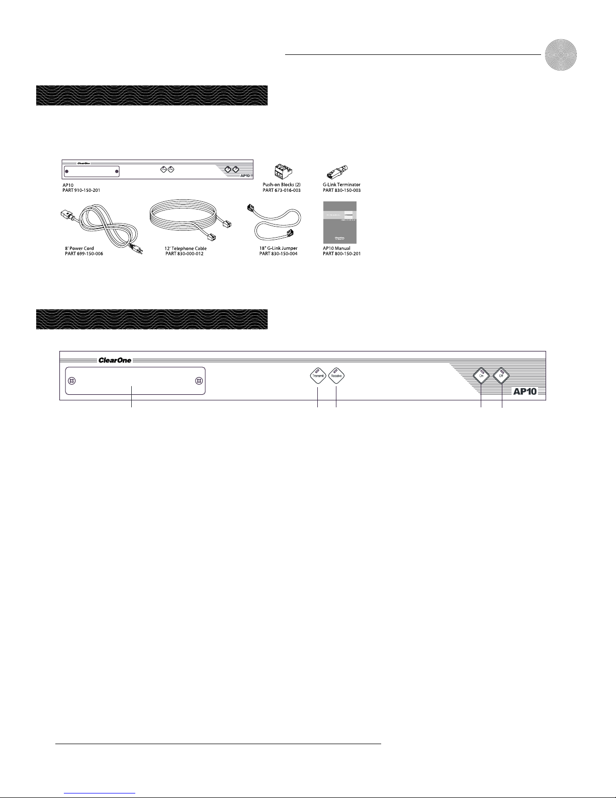
Ensure that the following items were received with your shipment:
!
Controls and Connections
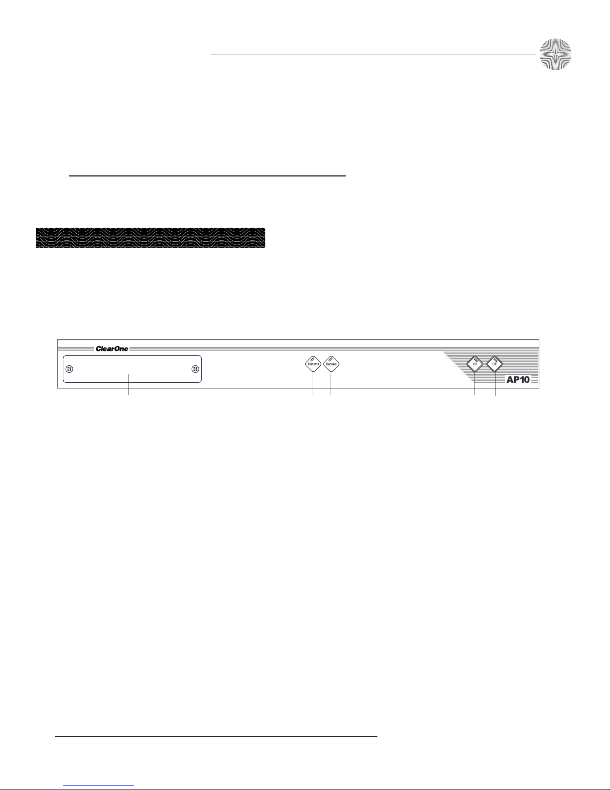
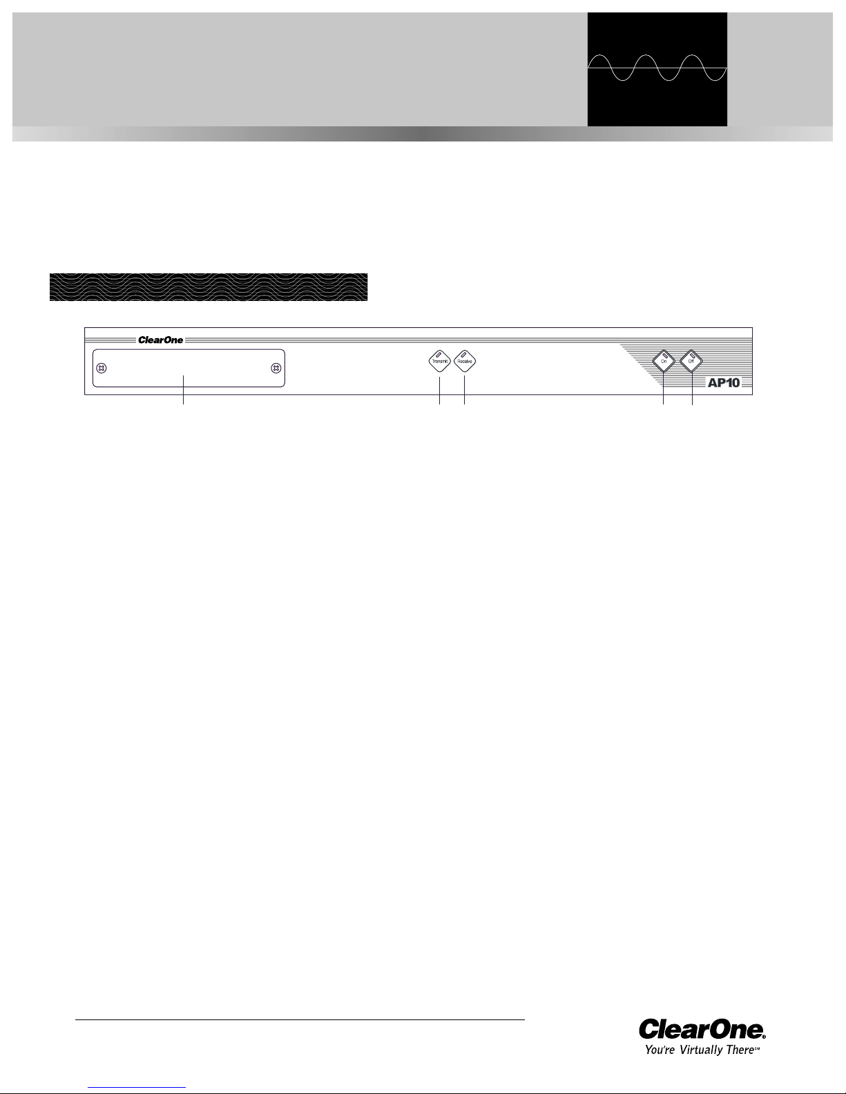
Front view
A.
DIP switches.
Operational features can be enabled or disabled via DIP
switches behind this panel. These features include auto-answer, auto-disconnect,
momentary or latching mode, device identification, caller AGC, caller boost, and
noise burst adapt/self adapt.
B. Transmit LED. This bicolor LED indicates the audio levels being transmitted
from the room to the telephone line.
C. Receive LED. This bicolor LED indicates the audio level the room is
receiving from the telephone line.
D. On. The On button connects the AP10 to the telephone line (dependent upon
DIP switch settings) and automatically adapts the hybrid to the line. The
LED will illuminate green when the hybrid is in the On state.
E. Off. The Off button disconnects the hybrid from the telephone line and mutes
all audio. The LED indicates the hybrid’s Off state. The LED will illuminate
red when the hybrid is in the Off state.
ABCD
E
Figure 1.2. AP10 front panel controls
Figure 1.1. AP10 unpacking diagram
Pressing and holding the
On button for more than a
half-second while the
hybrid is active will readapt the
hybrid.
✍

Introduction ~ Controls and Connections
4
Technical Services Group ~ 1-800-283-5936 (USA) ~ 1-801-974-3760
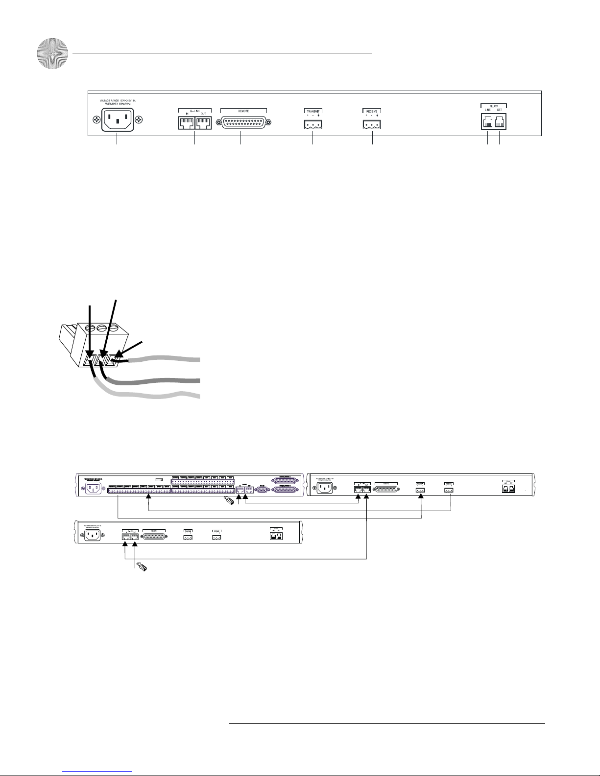
Rear view
A. Power. The AC power cord input is a NEMA-type connector allowing
100–240VAC, 50/60Hz.
B. G-Link In, Out. This RJ-45 connector is used to connect the AP10 to the
AP800 for control. AP-Ware is capable of accessing and controlling a
G-Link local area network (LAN) of up to eight AP800/AP400 units and
16 AP10 units. G-Link supports a distance of up to 20 feet between each
connected unit.
C. Remote. This DB-25 connector provides control and status of the AP10 and
unbalanced audio. See Appendix B for pinouts.
D. Transmit Input. This Phoenix connector is used to connect transmit audio
(input) from the AP800 to the AP10, which is then sent to the telephone
line.
E. Receive Output. This Phoenix connector is used to connect receive audio
(telephone participant audio) from the AP10 to the AP800.
F. Telco Line. This RJ-11 connector provides connection of a standard analog
telephone line to the hybrid.
G. Telco Set. This RJ-11 connector allows connection to a standard telephone
set. Tip and ring from the phone line are present at this connector when the
hybrid is in its off state. Tip and ring from the phone line are not present at
this point when the hybrid is in its on state.
ABCD
EFG
Figure 1.3. AP10 rear-panel connectors

5
Introduction ~ Before You Install
Technical Services Group ~ 1-800-283-5936 (USA) ~ 1-801-974-3760
Power requirements
The AP10 automatically accommodates voltage requirements of 100–240VAC,
50/60Hz, 15W.
Telephone line requirements
The AP10 model operates on a standard analog telephone line and connects to the
telephone system with a standard RJ-11C modular jack. If you do not have an
RJ-11C jack where you want to install your AP10, call your telephone company for
installation.
Equipment placement
The AP10 models are designed for installation in a standard 19-inch equipment
rack. You can also purchase side panels for desktop placement.
Environmental requirements
The AP10 can be safely operated in a room with varying temperatures between
32°F (0°C) and 100°F (38°C).
Before You Install

6
Technical Services Group ~ 1-800-283-5936 (USA) ~ 1-801-974-3760

Technical Services Group ~ 1-800-283-5936 (USA) ~ 1-801-974-3760
The AP10 is designed for easy installation and set-up. All connections are made
through rear-panel connectors. This section provides instructions on installing the
units in the rack and making initial connections, creating a G-Link network, and
assigning device ID numbers.
The diagram below illustrates the typical connections that are made when
adding an AP10 to an AP800.
CHAPTER 2: Installation
AP10
AP800
Telephone set
(optional)
Transmit
Input
Receive
Output
Microphones
Inputs
Touch panel
controller
G-Link connection
Line
Figure 2.1. System diagram
Hardware Setup
Connect the unit
Refer to the rear-panel drawing in Figure 2.2 on the following page. Each connector
is numbered for easy identification.
1. Place the unit in the rack and attach it securely. AP10 models are designed
for installation in a standard 19-inch equipment rack.
2. Connect your telephone line from the wall jack to the RJ-11C Line jack [F].
3. Plug your telephone set into the RJ-11C Set jack [G].
4. If you are using a custom controller for control and hybrid status, plug it
into the DB-25 Remote connector [C].
Installation ~ Hardware Setup
8
Technical Services Group ~ 1-800-283-5936 (USA) ~ 1-801-974-3760
5. Wire the AP10 to the AP800 using the provided three-terminal Phoenix
push-on connectors. These connectors are designed for easy wiring; simply
insert the desired wire into the appropriate connector opening and tighten
down the top screw.
•Transmit Input Audio connected to the Transmit Input [D] will be sent
down the telephone line.
•Receive Output Audio from the telephone participant is passed to
Receive Output [E].
Creating a G-Link network
1. Place the AP units in their proper locations. The back-panel G-Link In and
G-Link Out [B] connectors are designed for setting up your G-Link network.
G-Link connections between AP units are connected in daisy-chain fashion
using category five twisted-pair cable.
2. The first ClearOne unit in the chain must have the G-Link In connector
terminated with a G-Link terminator (provided).
3. The first ClearOne unit’s G-Link Out connector is then attached to the
G-Link In connector on the next unit in the chain. At the end of the network,
the final unit must have the G-Link Out connector terminated with a G-Link
terminator as well.
A G-Link network will allow interconnection of up to 16 AP10s and eight AP800s.
If the AP units are stacked vertically, connect them using the short RJ-45 jumper
(provided). If networking over longer distances (up to 20 feet/ 6.1 meters between
units), use Cat 5 twisted-pair (10BaseT LAN) cable.
ABCD
EFG
Figure 2.2. AP10 rear panel connectors
The three terminals in
the Phoenix connector
correspond with the back-
panel audio contacts (from left to
right): +(positive), –(negative), and
(ground).
✍
Figure 2.3. Phoenix push-on connector
+–
Ground
Negative
Positive
AP800
AP 10
G-Link
Terminator
G-Link
Terminator
AP 10
G-Link
G-Link
Audio:Transmit and Receive
Figure 2.4. G-Link connection block diagram

9
Installation ~ Hardware Setup
Technical Services Group ~ 1-800-283-5936 (USA) ~ 1-801-974-3760
If more than one AP10 is
assigned the same device
ID number, the Transmit
and Receive LEDs will flash red and
green on the affected units until the
error is corrected.
!
Assigning device ID numbers
Once your physical G-Link network is established, you need to set up unique G-Link
device ID numbers for each AP10 on the network. As shipped from the factory, all
AP10 units default as binary address 0. Set device ID numbers for each AP10 unit
at your site by manipulating front-panel DIP switches 9–12, selecting/deselecting
each switch to set up address 0–15 in binary code. Use the table below to determine
the proper DIP switch settings for the device ID you want to assign.
Connecting power
The power input [1] will operate at any level between 100–240VAC, 50–60Hz, 15W
(typical). Plug in the AP10 to complete the hardware installation.
Device ID DIP switch settings
Binary DIP Switch 9 DIP Switch 10 DIP Switch 11 DIP Switch 12
Address Position Position Position Position
0 0 (DOWN) 0 (DOWN) 0 (DOWN) 0 (DOWN)
1 0 (DOWN) 0 (DOWN) 0 (DOWN) 1 (UP)
2 0 (DOWN) 0 (DOWN) 1 (UP) 0 (DOWN)
3 0 (DOWN) 0 (DOWN) 1 (UP) 1 (UP)
4 0 (DOWN) 1 (UP) 0 (DOWN) 0 (DOWN)
5 0 (DOWN) 1 (UP) 0 (DOWN) 1 (UP)
6 0 (DOWN) 1 (UP) 1 (UP) 0 (DOWN)
7 0 (DOWN) 1 (UP) 1 (UP) 1 (UP)
8 1 (UP) 0 (DOWN) 0 (DOWN) 0 (DOWN)
9 1 (UP) 0 (DOWN) 0 (DOWN) 1 (UP)
10 (A) 1 (UP) 0 (DOWN) 1 (UP) 0 (DOWN)
11 (B) 1 (UP) 0 (DOWN) 1 (UP) 1 (UP)
12 (C) 1 (UP) 1 (UP) 0 (DOWN) 0 (DOWN)
13 (D) 1 (UP) 1 (UP) 0 (DOWN) 1 (UP)
14 (E) 1 (UP) 1 (UP) 1 (UP) 0 (DOWN)
15 (F) 1 (UP) 1 (UP) 1 (UP) 1 (UP)

10
Technical Services Group ~ 1-800-283-5936 (USA) ~ 1-801-974-3760

Technical Services Group ~ 1-800-283-5936 (USA) ~ 1-801-974-3760
The AP10 has a variety of operational features configurable through DIP switch
settings, including noise burst/auto-adapt, receive AGC control, auto-answer, auto-
disconnect, call progression/loop, receive reduction, and hook-flash duration. Default
settings (as shipped from the factory) are denoted by an asterisk “*”.
Noise burst/auto-adapt
In some applications, you might want to adapt the hybrid with a white noise burst,
rather than allow the hybrid to adapt automatically to line conditions. To enable this
feature, set DIP switch 1 to the On position.
DIP Switch Position Description
1 On (up) Burst adapt
1* Off (down) Auto-adapt
Receive boost
If incoming caller audio is consistently low, activate the Receive Boost. This will
increase receive audio by 6dB. To enable this feature, set DIP switch 2 to the On
position.
DIP Switch Position Description
2 On (up) 6dB Receive audio boost enabled
2* Off (down) 6dB Receive audio boost disabled
CHAPTER 3: Configuration
DIP Switch Settings
Figure 3.1. AP10 DIP switches

Configuration ~ DIP Switch Settings
12
Technical Services Group ~ 1-800-283-5936 (USA) ~ 1-801-974-3760
Receive AGC
DIP switch 3 enables/disables the automatic gain control (AGC) function in the
firmware. The AGC feature is designed to keep soft and loud telephone participants
at a consistent level.
DIP Switch Position Description
3* On (up) Receive AGC enabled
3 Off (down) Receive AGC disabled
Auto-answer
DIP switch 4 enables/disables auto-answer. When enabled, the AP10 will
automatically answer incoming calls after one complete valid ring has been detected.
DIP Switch Position Description
4 On (up) Auto-answer enabled
4* Off (down) Auto-answer disabled (follows
the serial command)
Auto-disconnect
DIP switch 5 enables/disables auto-disconnect.
DIP Switch Position Description
5* On (up) Auto-disconnect enabled
5 Off (down) Auto-disconnect disabled
Call progression/loop
DIP switch 6 selects either loop drop or call-progress mode. Call-progress mode will
disconnect the line upon detection of a valid call-progress signal. Call progress will
detect the reorder tone and busy signal for the U.S., Canada, United Kingdom,
France, and Germany.
DIP Switch Position Description
6 On (up) Call progression enabled
6* Off (down) Loop drop enabled
To issue the AA (auto-
answer) serial command to
toggle auto-answer, DIP
switch 4 must be off (down).
In order for the settings on
DIP Switch 6 to function,
DIP Switch 5 must be on
(up). Auto-disconnect must be
enabled before either Call
Progression or Loop Drop are
applicable.
✍
✍
13
Configuration ~ Calibration
Technical Services Group ~ 1-800-283-5936 (USA) ~ 1-801-974-3760
Receive reduction
In some applications, it might be necessary to duck (lower) the receive audio coming
in through the telephone line when transmit audio is present. To enable receive
reduction, set DIP switch 7 to the On position.
DIP Switch Position Description
7 On (up) Receive reduction enabled
7* Off (down) Receive reduction disabled
Calibration
The following information will help you make adjustments to optimize your system
performance. Verify all components and all connections. Ensure that proper power is
supplied to the AP10 and that the unit is off (indicated by the red Off LED). If the
green On LED is lit, press the Off button [E].
There are two calibration methods for the AP10: noise burst and auto-adapt.
Which procedure is used depends on whether you have DIP switch 1 on (up) for
noise-burst adapt, or DIP switch 1 Off (down) for auto-adapt. Either will suffice to
calibrate the AP10. The difference is the application and/or personal preference.
Some applications are not suited for a .75-second noise burst, and might require
the gradual adaptation over time.
Noise burst adapt
If DIP switch 1 is on (up), have someone call the AP10 from another location.
Answer the line by pressing the On button [D]. (If the auto-answer feature is active,
the unit will answer the call after one complete ring.)
The caller will hear a short white noise burst (it will sound like static) and a
short beep. This automatically adapts the AP10 to the telephone line.
ABCD
E
Figure 3.2. AP10 front-panel controls
Some echo and ringing
might be heard while
calibrating the AP10.
Disregard it and continue with
calibration until the end of the
procedure. The echo and ringing
will disappear.
✍

Configuration ~ Calibration
14
Technical Services Group ~ 1-800-283-5936 (USA) ~ 1-801-974-3760
Auto-adapt
If DIP switch 1 is off (down), call someone and continue to talk while the system
gradually adapts over time. Once complete, the AP10 will be fully calibrated and
ready for use. Press the Off button [E]. If the auto-disconnect feature is active, and
the caller hangs up, the AP10 will disconnect upon sensing loop drop or call-
progress tones, depending on the position of DIP switch 6.
Transmit level adjustment
Someone in the local room should speak into the microphone at a normal distance,
in a normal voice. The party at the distant location should not speak during the
transmit adjustment. Adjust the AP800 output that is connected to the AP10
Transmit input to 0dB. The AP10 Transmit LED [B] should illuminate solid green
while the person is speaking and extinguish when the person stops.
Receive level adjustment
Someone in the distant location should speak into the microphone at a normal
distance, in a normal voice; the local room should maintain silence. Adjust the
AP800 input that is connected to the AP10 Receive output to 0dB. The AP10
Receive LED [C] should be solid green while the person is speaking and extinguish
when the person stops.
AP10 transmit and receive
audio level adjustments
are made using the
AP800. Nominal transmit and
receive level for the AP10 is 0dBu.
✍
Technical Services Group ~ 1-800-283-5936 (USA) ~ 1-801-974-3760
The AP10 has four basic functions: make a call, answer a call, disconnect a call, and
mute. This chapter explains how to perform these functions with the AP10 unit and
a telephone handset (optional) and with the Telco interface in AP-Ware. You can also
use touch panels and custom control devices.
To answer a call
Depending on how you have configured your AP10, an incoming call can ring on the
telephone set connected to the AP10, the receive output, and pass a serial ring to the
control device. An incoming call will also cause the front panel On LED to flash. You
can answer the call in one of two ways:
• Press the On button [D] on either the front panel or from your remote
control. This will route the call through the AP10 to the AP800. The green
On LED will light. The red Off LED will extinguish.
– or –
• Answer the call by picking up the telephone handset and talking to your
party over the telephone.
To make and disconnect a call
1. Call the party using your handset.
2. After the other party has answered, route the call through the AP10 by
pressing the On button [D]. The On LED will light and the AP10 will take
control of the call, disabling the telephone set. You can now safely hang up
the handset without disconnecting your call.
If using an external controller, it is not necessary to press the On button
[D]. The DIAL serial command automatically engages the AP10. See Serial
Commands, page 22.
CHAPTER 4: Operation
Using the AP10
ABCD
E
Figure 4.1. AP10 front panel controls
If auto-answer is enabled
(DIP switch 4), the AP10
will answer after the first
complete ring.
✍
If auto-disconnect is
enabled (DIP switch 5),
the AP10 will disconnect
upon sensing loop drop or call-
progress tones (depending on the
position of DIP switch 6).
✍
Operation ~ Using the Telco Interface
16
Technical Services Group ~ 1-800-283-5936 (USA) ~ 1-801-974-3760
3. When the conversation is complete, press the Off button [E] to disconnect
the call. You can also disconnect using an external controller. If the handset
is off hook, audio will be routed to the telephone.
If your call is through the handset only (the red Off LED will be lit), hang up
when the conversation is complete.
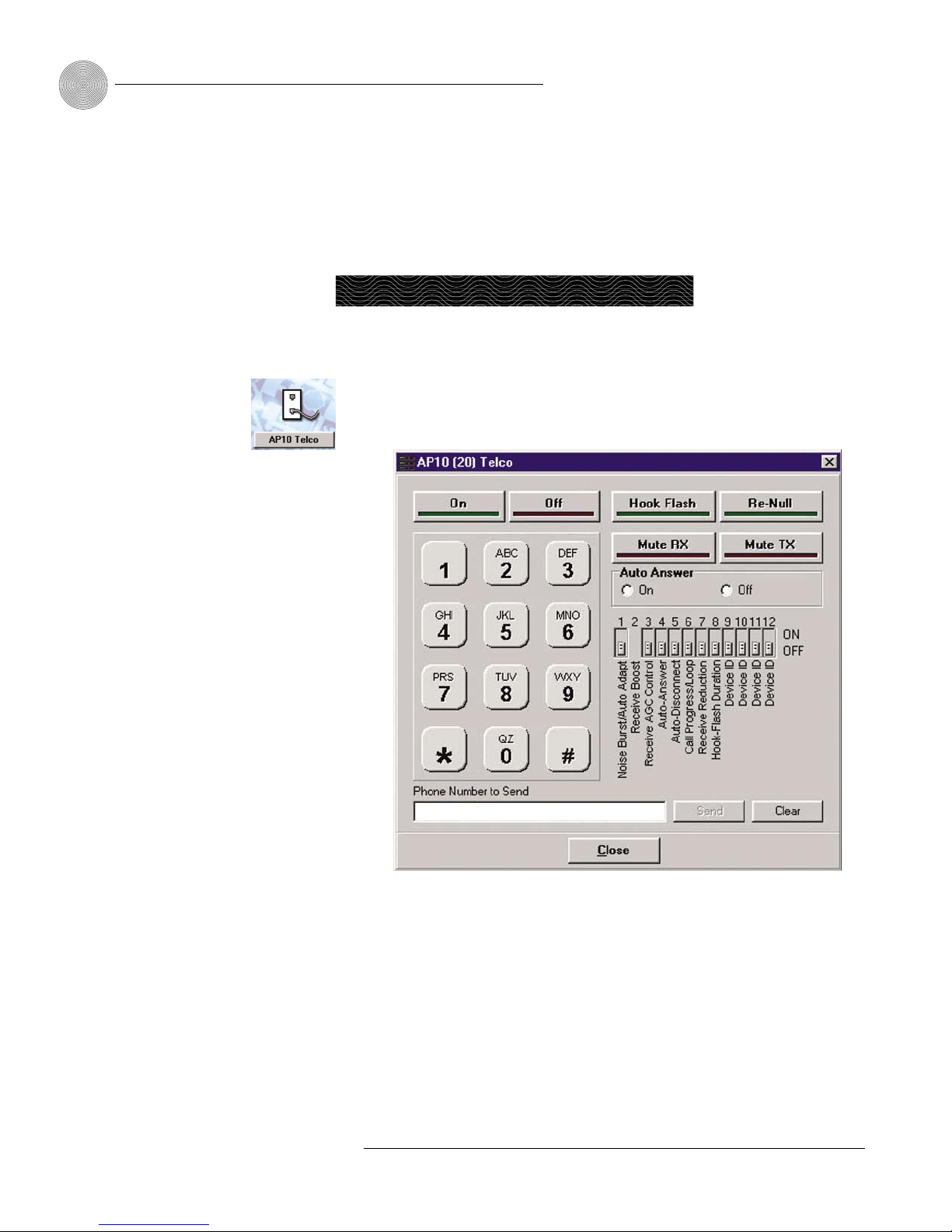
To make and disconnect a call
1. Open AP-Ware and select the AP10 unit.
2. Click the AP10 Telco button on the Flow Screen to open the Telco interface.
3. Activate the telephone interface by clicking On
or by beginning to dial
.
4. When the green light below the On button illuminates, enter the number to
be dialed, including any dial-out prefixes.
5. Click Send. If you clicked directly on the number buttons, the call will be
completed as you finish dialing—just like using a standard telephone.
6. When you are finished with the call, click Disconnect to end the call.
Using the Telco Interface
Figure 4.2. Telco dialing interface
Detailed instructions on
creating site files and
using AP-Ware can be
found in the AP-Ware help file.
✍
Table of contents
Other Clear One Recording Equipment manuals


