Clear Water ComAir 20T User manual

Ozone Systems
Installation & Operation Manual
ComAir 20T
Commercial Indoor Air Purification System
ClearWater Tech, LLC.
Integrated Ozone Systems
850-E Capitolio Way, San Luis Obispo, Ca 93401 • 805-549-9724 • Fax: 805-549-0306 • E-mail: service@cwtozone.com • www.cwtozone.com
Copyright © 2020 - ClearWater Tech, LLC • Reproduction of any kind is prohibited • LIT104 • Rev 102120

-1-
O3
INTRODUCTION
This Installation and Operation Manual is
written to assist in the installation, operation
and maintenance of air purification systems
manufactured by ClearWater Tech, LLC. This
equipment has been designed using the most
modern materials and technology available.
Please read this manual carefully and in its
entirety before proceeding with any
installation, operation or maintenance
procedure associated with this equipment.
Failure to follow these instructions could result
in personal injury, damage to the equipment or
reduced product performance.
In an ongoing effort to improve reliability and
operating efficiency, ClearWater Tech may find it
necessary to make changes to its products.
Therefore, the information contained in this
manual may not conform in every respect to earlier
versions of ClearWater Tech ozone systems found
in the field. If you have any questions, please
contact your ClearWater Tech dealer or the
ClearWater Tech service department.

-2-
TABLE OF CONTENTS
Safety Information ..........................................................................................................3
Theory of Operation/Product Description.....................................................................4
Figure 1 – ComAir 20T External Components.............................................................4
Figure 2 – Typical ComAir 20T Installation ................................................................5
Installation Procedures...................................................................................................6
Unpacking....................................................................................................................6
Assembling the ComAir 20T .......................................................................................6
Figure 3 – Assembled ComAir 20T .............................................................................7
Picking an Installation Location...................................................................................7
Figure 4 – ComAir 20T Installation Locations.............................................................7
ComAir 20T Installation ..............................................................................................8
Figure 5 – How to Flip the Cover Orientation ..............................................................8
Figure 6 – Cover Orientation Options ..........................................................................8
Figure 7 – Airflow Sensitivity Jumper .........................................................................9
Setting the ComAir 20T .............................................................................................10
Figure 8 – Control Board Dip Switches .....................................................................10
Table 1 – Control Board Dip Switch Settings ............................................................10
Adjusting the ComAir 20T – Without Ambient Ozone Controller .............................11
Table 2 – Mode Selection Guidance, Without Ambient Ozone Controller .................11
Adjusting the ComAir 20T – With Ambient Ozone Controller ..................................11
Table 3 – CWT Ambient Ozone Controller Connections ...........................................12
Table 4 – Dip Switch Settings to use CWT Ambient Ozone Controller .....................12
Table 5 – Mode Selection Guidance, With Ambient Ozone Controller ......................12
Optional Accessories – Remote Display and Ambient Ozone Controller ...................13
Figure 9 – Remote Display ........................................................................................13
Figure 10 – Ambient Ozone Controller ......................................................................13
Maintenance ..................................................................................................................14
Figure 11 – Main Components...................................................................................16
Troubleshooting ............................................................................................................17
Appendix A – Specifications.........................................................................................18
Appendix B – Parts List................................................................................................20
Appendix C – Warranty Information..........................................................................21

-3-
Safety Information
Always make sure the system is unplugged during installation or service procedures.
WARNING: THE ULTRAVIOLET LIGHT PRODUCED BY THE UV LAMPS IS
HARMFUL TO THE EYES. DO NOT LOOK DIRECTLY AT THE
LAMPS. SHOULD IT BECOME NECESSARY TO LOOK AT THE
LAMPS, USE UV-PROTECTED SUNGLASSES.
IMPORTANT SAFETY INSTRUCTIONS
When installing and using this electrical equipment, basic safety precautions should always be followed,
including the following:
1. READ AND FOLLOW ALL INSTRUCTIONS.
2. Connect to a grounded, grounding type receptacle only.
3. Warning – To reduce the risk of electrical shock, replace damaged cord immediately.
4. Warning: For indoor use only. This unit is not intended for outdoor use.
5. Do not look at the UV lamps. Ultraviolet light is harmful to the eyes.
6. Fully install unit in the duct before plugging it into power.
7. SAVE THESE INSTRUCTIONS.
-4-
Theory of Operation/Product Description
The ComAir 20T is designed to help remove pathogens and odors ranging from food, tobacco smoke,
pets, and other objectionable smells that may be present in your business or residence.
This system from ClearWater Tech utilizes two different Ultraviolet lamps creating UV light at two
distinct wavelengths. The ozone lamp creates light at 185nm, which is easily absorbed by oxygen
molecules. This added energy causes the oxygen molecules to break apart into single oxygen atoms, which
then combine with other oxygen molecules to create ozone. Ozone is the world’s most powerful natural
oxidizer. It is effective at oxidizing pathogens (bacteria, viruses, mold, etc.), as well as VOCs, odor,
smoke, and allergens.
The germicidal lamp creates light at 254nm, which is absorbed by DNA molecules in unwanted pathogens.
The extra energy disrupts the DNA molecule inhibiting the pathogen from reproducing.
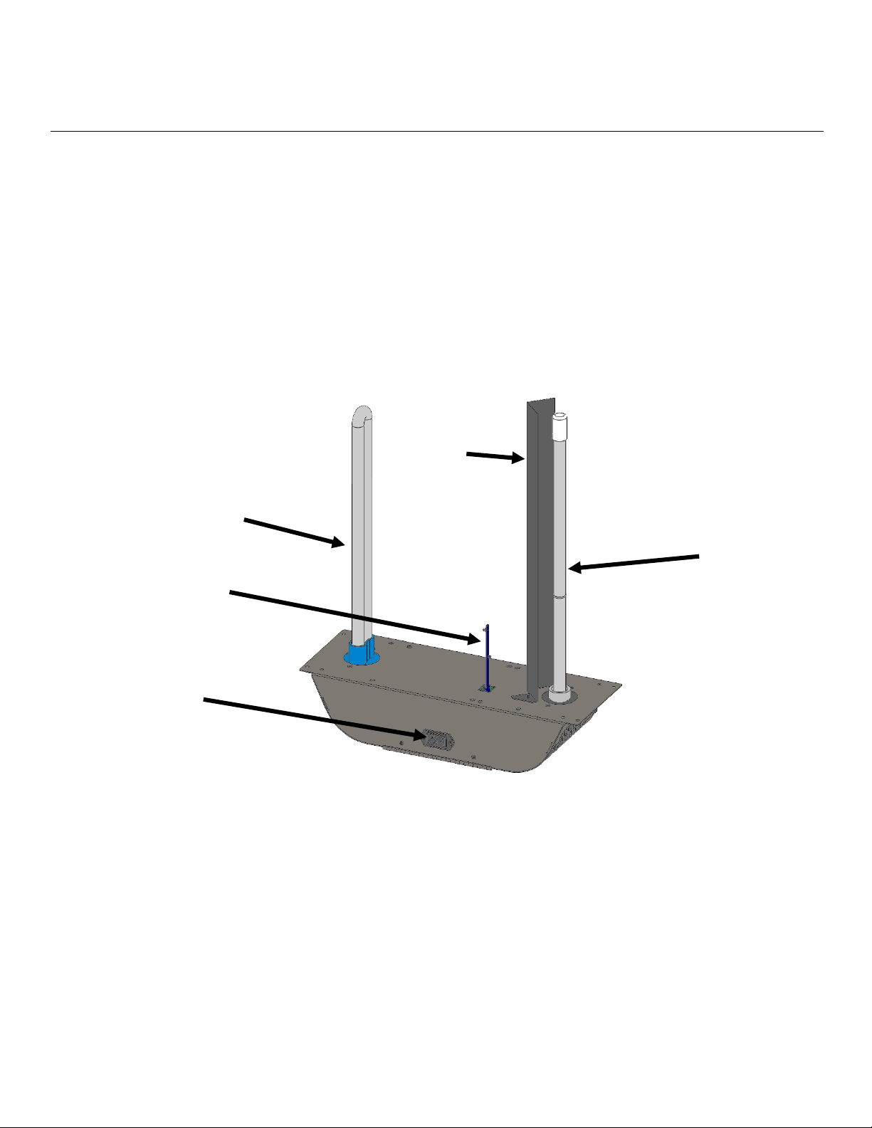
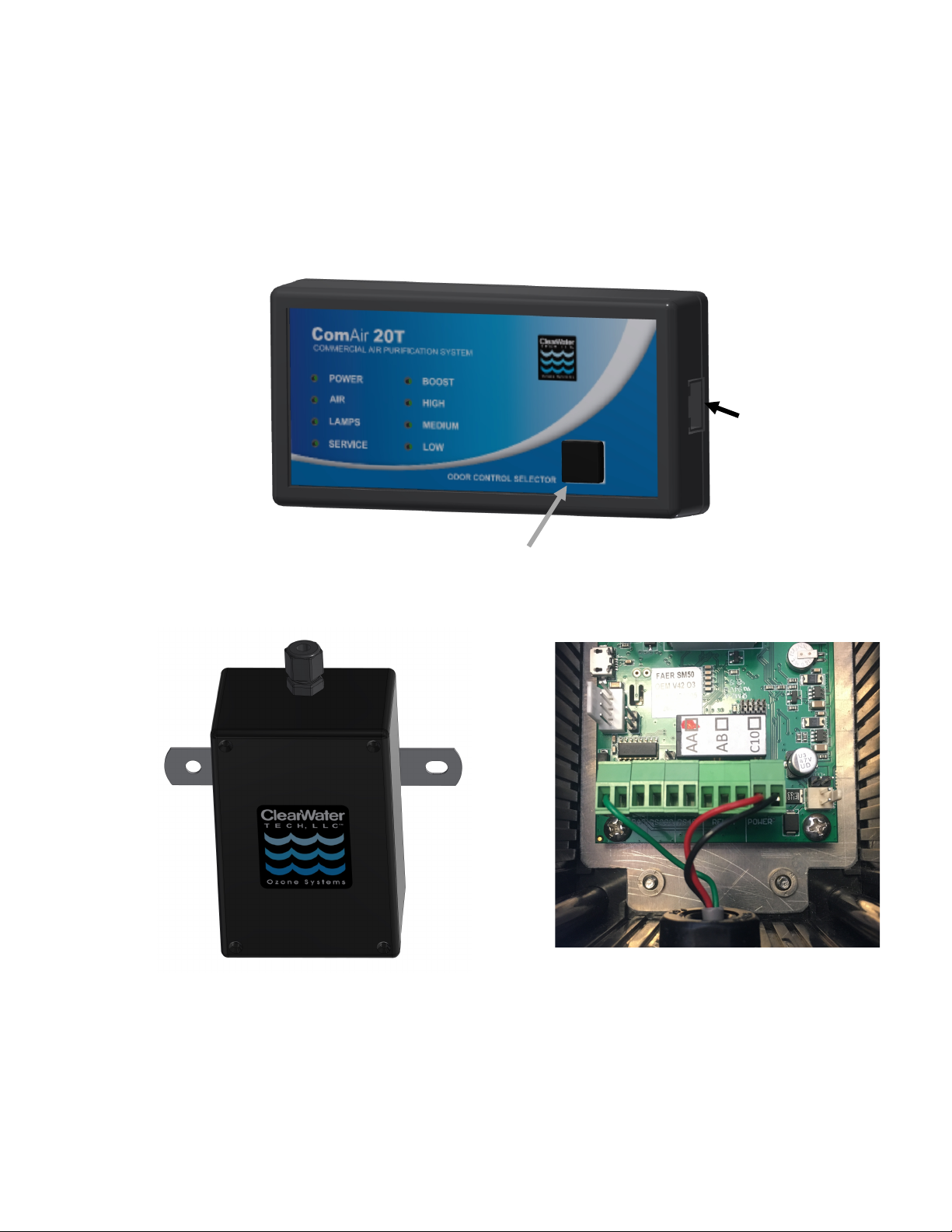
Figure 1 – ComAir 20T External Components
The ComAir 20T is designed to install easily into the air duct, placing the ozone UV lamp, germicidal UV
lamp, and an airflow sensor into the air stream. As air passes through the air duct the airflow sensor will
initiate power to both UV lamps. Incoming air will first pass by the high-powered germicidal UV lamp.
Pathogens in the air stream will be sterilized as the Ultraviolet light disrupts their DNA. As the air
continues to travel down the duct the air will pass by the ozone lamp where a small amount of ozone will
be created in the airflow. This ozone will then travel with the air through the ducting where its oxidation
of pathogens and other contaminants takes place.
Germicidal Lamp
Ozone Lamp
Airflow Sensor
Ozone
Lamp
Shield
Power Inlet

Theory of Operation/Product Description
-5-
Figure 2 – Typical ComAir 20T Installation
An optional ozone sensor allows the ComAir 20T to regulate the ozone output levels produced within the
ducting. This ensures safe environmental levels in the occupied space. An optional remote display allows
the ComAir 20T to be monitored and controlled in a more convenient location.
ComAir 20T
Optional
Remote
Display
Optional
Ozone
Controller

-6-
Installation Procedures
Unpacking
Carefully remove the parts from the package. The lamps are fragile and proper care must be taken when
removing packaging that is placed around them.
DO NOT TOUCH THE LAMPS WITH YOUR BARE HANDS AS OILS FROM YOUR HANDS
CREATE “HOT SPOTS” WHICH REDUCE THE LAMP LIFE. In case of contact with the lamp, wipe
the lamp clean with a soft cloth dampened with rubbing alcohol.
In addition to this manual, check to make sure you have all of the following parts:
• ComAir 20T
• Ozone Lamp
• Germicidal Lamp
• Lamp Shield
• Airflow Sensor PCB
• Self-tapping Screws (Quantity 4)
• Installation Template
• Power Cord
Assembling the ComAir 20T
1. Remove the screws from the cover of the unit and open the cover.
2. See figure 3 for locations of components. Install lamp shield by using the hardware that is attached
to the main unit. Attach the shield to the main unit and tighten the two nuts.
3. Install the Ozone lamp
a. Loosen the lamp lock nut from the lamp holder by turning it counterclockwise and remove.
b. Remove the metal washer and the rubber bushing from the lamp holder and install the rubber
bushing on the lamp base.
c. Slide the lamp into the lamp opening. Handle lamp by the end cap.
d. Re-install the metal washer and lamp lock nut.
e. Carefully tighten the lamp lock nut.
f. Connect the lamp connector to the end of the lamp.
g. Make sure the other side of the lamp connector is inserted completely on the daughter board
lamp pins.
4. Install the Germicidal lamp
a. Remove nuts and washers from the mounting studs.
b. Place the two rubber washers on the mounting studs first.
c. Slide the lamp into the main unit and align so the mounting ears on the lamp go through the
mounting studs on the main unit.
d. Install the hard-plastic washers and nuts.
e. Tighten the nuts snugly, but do not over tighten
f. Connect the lamp connector to the end of the lamp.
g. Make sure the other side of the lamp connector is inserted completely on the main ballast board
lamp pins.
5. Insert the Airflow Sensor PCB into the hole on the bottom of the unit. The sensor connector is
keyed so it can only go in one way.
6. Make sure the ribbon cable is inserted completely in the main ballast board and the control board
on the cover.
Installation Procedures
-7-
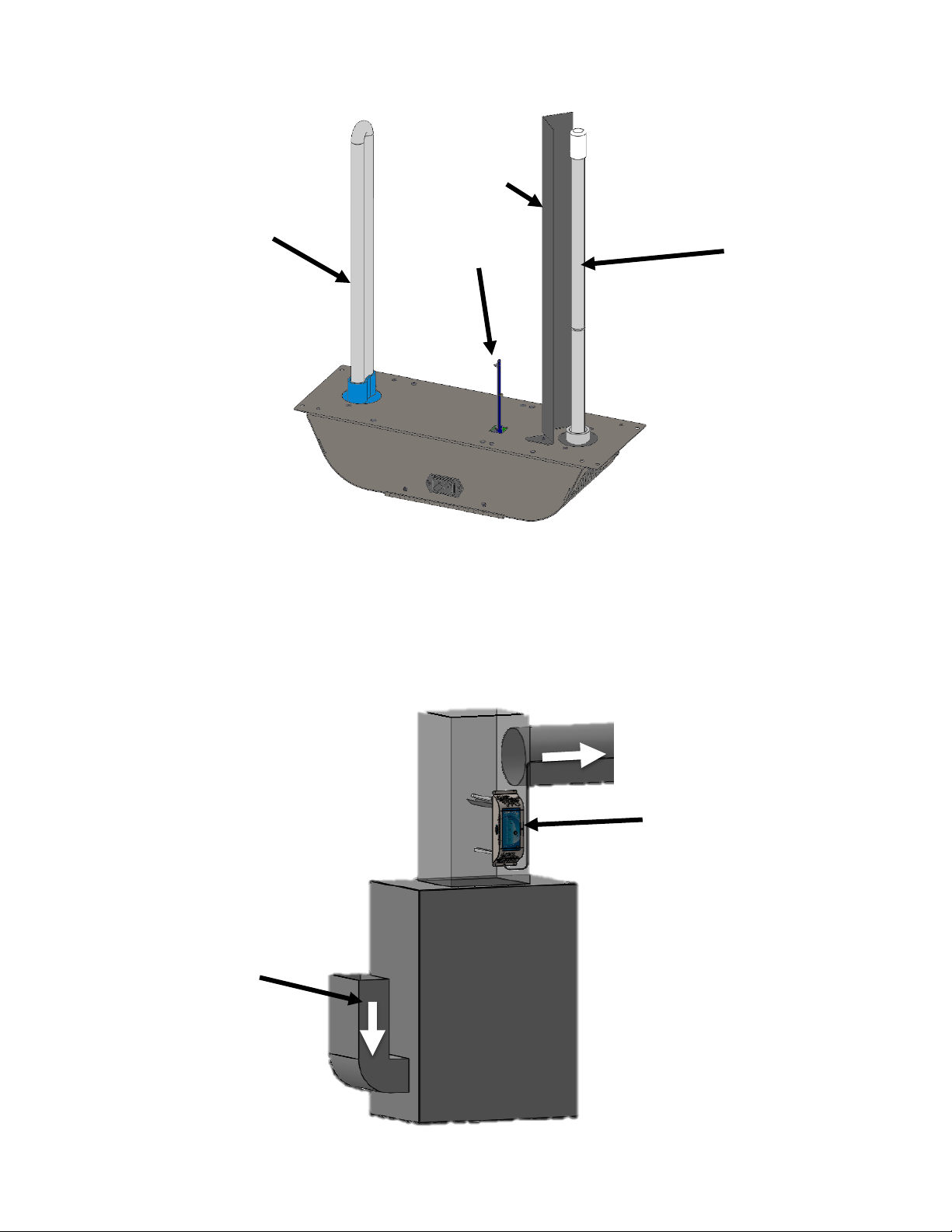
Figure 3 – Assembled ComAir 20T
Picking an Installation Location
The ComAir 20T may be installed either in the main return duct or the main supply duct as shown in the
Figure 4 below. When installing on the supply side, locate it as far away from the heating source as
practical while remaining in the main air stream.
Figure 4 – ComAir 20T Installation Locations
Supply Side
Return Side
Ozone Lamp
Lamp Shield
Airflow
Sensor
Germicidal Lamp
Installation Procedures
-8-
ComAir 20T Installation
While performing installation procedures all power to the unit must be ‘Off’ and there should be no airflow
through the heating/cooling system.
1. A template may be used for installation of the ComAir 20T. The template is included in the
shipping box. Refer to figure 4 for mounting locations.
2. If possible, install the ComAir 20T so the airflow passes over the germicidal lamp first and then
passes over the ozone lamp. The cover can be reversed by removing the hinge nuts and attaching
the hinge cover to the opposite side of the chassis. This will allow the cover to be oriented so it is
easy to read and operate the unit once it is installed.
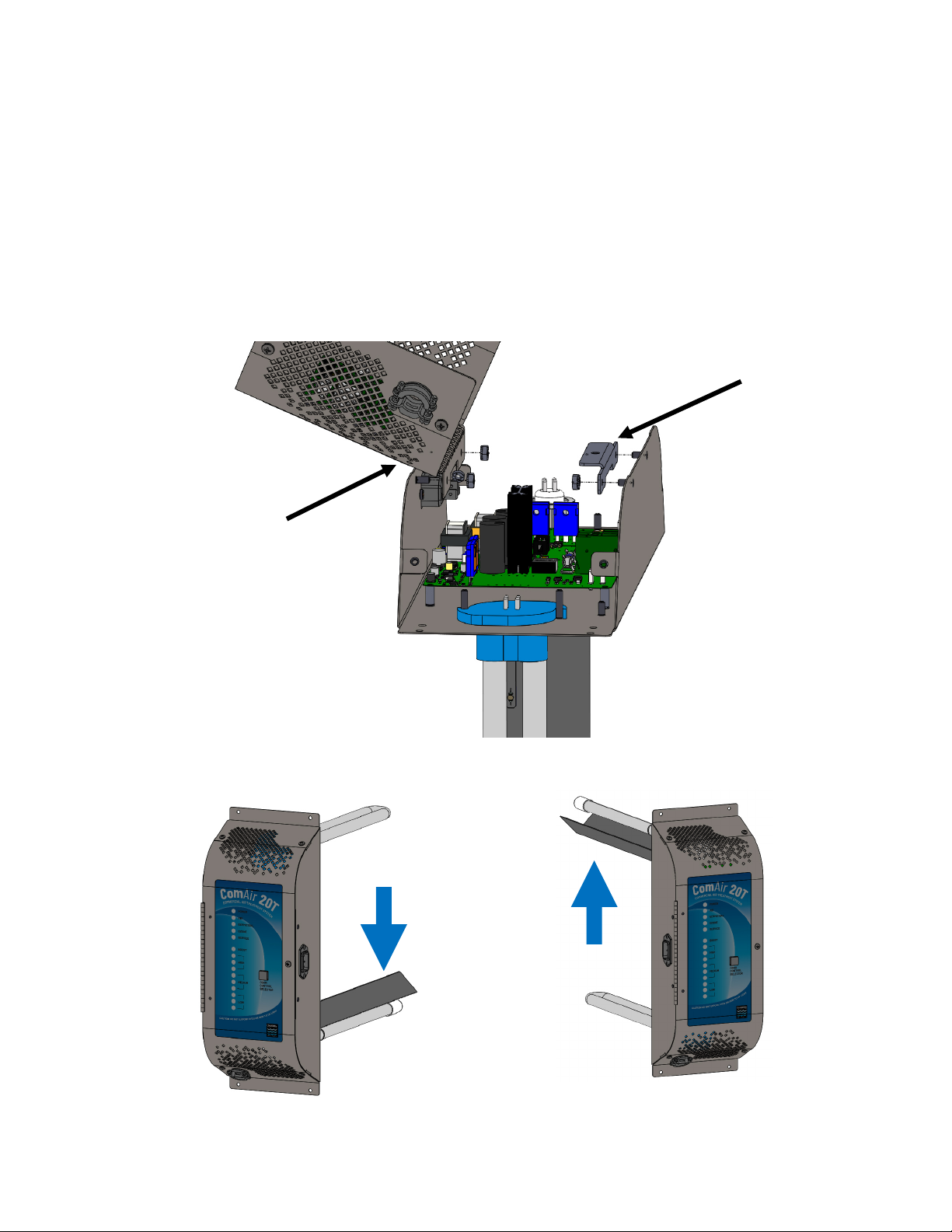
Figure 5 – How to Flip the Cover Orientation
Figure 6 – Cover Orientation Options
Remove
bracket and
move to
other side
Remove
cover and
move to
other side
Airflow
Airflow

Installation Procedures
-9-
3. Attach the installation template to the ductwork using tape.
4. Cut out openings in ductwork for the unit. See template for steps and recommended tools.
5. There are 4 mounting holes provided inside the cover and 4 mounting holes provided on the outside
of the unit. Either set of holes are acceptable to use. Position the ComAir 20T into ductwork and
secure with the self-tapping screws provided, using a 5/16” nut driver.
6. Close the cover and secure with the cover screws.
7. Connect main power to a non-switched power supply (90-265 VAC). Note: On initial startup, the
‘Power, Air, Germicidal, Ozone and Low’ lights will remain on for 30 to 120 seconds. After this
time the ‘Air, Germicidal and Ozone’ lights will turn ‘Off’. If the lights do not turn ‘Off’, the
airflow sensitivity might need to be adjusted to be less sensitive. The system can be set for L - Low
Sensitivity (more airflow is required to turn the system ‘On’), M - Medium Sensitivity and H -
High Sensitivity (less airflow is required to turn the system ‘On’). See figure 7 below for location
of airflow sensitivity jumper.
Figure 7 – Airflow Sensitivity Jumper
8. Turn ‘On’ heating/cooling system and allow it to operate for five minutes, at this time the ‘Air,
Germicidal and Ozone’ lights should illuminate. If the lights do not turn ‘On’, the airflow
sensitivity might need to be adjusted to be more sensitive. See figure 7 for the airflow sensitivity
jumper.
9. Turn ‘Off’ heating/cooling system, the ComAir 20T will shut-down within 5 to 30 seconds. After
this time the ‘Air, Germicidal and Ozone’ lights will turn ‘Off’. The ‘Power’ and ‘Low’ lights will
remain on when unit is not in operation.
10. The ComAir 20T is now ready for use.
Note: Ozone air treatment occurs only when air is circulating through the heating/cooling system.
For maximum effectiveness and continuous air purification, turn the thermostatic controller switch
from the ‘AUTO’ position to the ‘ON’ position. The switch is located on the thermostat. Open
windows or doors and dirty ductwork may diminish the unit’s effectiveness.
Airflow
Sensitivity
Jumper
Installation Procedures
-10-
Setting the ComAir 20T
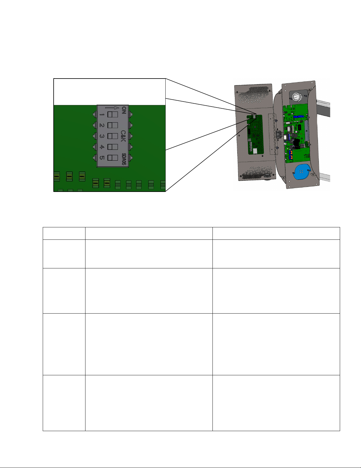
Inside the cover on the Control Board are 5 dip-switches that allow the Control Board to be configured
for your particular installation.
Figure 8 – Control Board Dip Switches
Moving from the top of the control board down:
Table 1 – Control Board Dip Switch Settings
Switch
When Positioned Left (Off)
When Positioned Right (On)
Switch 1
The ten LEDs will indicate the signal level
coming into the control board from the
ambient ozone controller inputs.
The ten LEDs will indicate the current
mode of the ComAir 20T.
Switch 2
The ComAir 20T will expect a signal from
an ambient ozone controller to regulate the
ozone output.
The ComAir 20T will not use an ambient
ozone controller to regulate the ozone
output. It will provide output equal to 25%,
50%, 75% or 100% of the max lamp output
determined by Mode setting.
Switch 3
The ambient ozone controller connected to
the ComAir 20T provides a continuous
voltage or current signal proportional to the
ozone. For example, the controller
provides a 0-5V signal with 0 volts equal
to 0 ppm ozone, and 5 volts equal to 0.5
ppm of ozone.
The ambient ozone controller connected to
the ComAir 20T provides a relay signal.
The relay is closed when the ozone level is
below the set point set on the controller,
and open when the ozone level is above the
set point set on the controller.
Switch 4
The ambient ozone controller connected to
the ComAir 20T is in a higher range:
0-5V with 5V = 0.5ppm
Or
4-20mA with 20mA = 1ppm
The ambient ozone controller connected to
the ComAir20T is in a lower range:
0-2V with 2V = 0.1ppm
Or
4-20mA with 20mA = 0.1ppm

Installation Procedures
-11-
Switch 5
The ComAir 20T is ready to communicate
with the Remote Display through the RJ-
45 connector
The ComAir 20T is sending serial data
through the RJ-45 connector that can
communicate with an external serial
device.
Adjusting the ComAir 20T – Without Ambient Ozone Controller
The output level adjustment push button is on the front cover. The settings are low, medium, high and
boost. Press the button on the cover of the unit to cycle the settings from low to boost and then back to
low. The unit will default to the low setting on initial power up.
Table 2 – Mode Selection Guidance, Without Ambient Ozone Controller
Mode
Ozone Output %
HVAC Unit Capacity
Space Square Footage
Low
25%
5 - 8.75 Tons
1500 – 2600 ft2
Medium
50%
8.75 – 12.5 Tons
2600 – 3750 ft2
High
75%
12.5 – 16.25 Tons
3750 – 4900 ft2
Boost
100%
16.25 – 20 Tons
4900 – 6000 ft2
Note: Buildings with heavy tobacco smoke or other strong odors can use higher settings than the
recommendations in Table 2.
When the ComAir 20T is in low mode, the ozone lamp will cycle ‘On’ and ‘Off’ every 5 minutes. This is
to create an ozone output level lower than is possible by simply dimming the ozone lamp. While in this
mode, the ozone lamp indicator LED will flash.
Adjusting the ComAir 20T – With Ambient Ozone Controller
An optional ambient ozone controller is available that detects the ozone concentration in the duct of the
heating/cooling duct. These instructions will describe how to correctly connect and use the ClearWater
Tech ambient ozone controller. If a different ozone sensor is used, please refer to the instruction manual
for that sensor, as well as “Setting the ComAir 20T” section above to properly set up the sensor with the
ComAir 20T.
The ComAir 20T will read the signal from the controller and adjust the Ozone output to maintain a
constant ozone level. The connections for the controller are on the ComAir20T Control Board mounted
to the cover. The cover must be opened to access the Control Board. A three-conductor cable with wire
sizes of 22 gauge or thicker is recommended for the connection. The cable should be routed through the
strain relief mounted on the cover of the ComAir 20T. See figure 11.
The ambient ozone controller supplied by ClearWater Tech should be mounted on the closest supply
register to the ComAir 20T. The sensor box requires a hole in the duct for the sensor to fit into and two
holes to be drilled for the attachment to the duct with sheet metal screws. A template that can be used to
locate the holes is provided with the controller.

Installation Procedures
-12-
Table 3 – CWT Ambient Ozone Controller Connections
ComAir 20T Connection
Controller Connection
Suggested Wire Color
12V
V+
Red
GND
GND
Black
Sig/Relay 0-5V
0-5V
Green
To use the ambient ozone controller, the switches on the ComAir20T Control Board must be set correctly:
Table 4 – Dip Switch Settings to use CWT Ambient Ozone Controller
Switch
Position
Setting
Switch 1
Right (On)
LEDs Show Mode
Switch 2
Left (Off)
Controller Connected
Switch 3
Left (Off)
Controller is Continuous Signal
Switch 4
Left (Off)
Controller is Higher Range
Switch 5 will be set based on whether a remote display is connected, or if the ComAir 20T is
communicating to a serial device. See the “Setting the ComAir 20T” section.
Once the system is powered up, the desired ozone output can be selected using the button on the cover of
the ComAir 20T or optional Remote Display. Holding down the button on the cover or optional Remote
Display for 3-4 seconds activates Boost Mode. After 30 minutes the ComAir 20T will automatically go
back to the mode it was in before it went into Boost Mode.
Table 5 - Mode Selection Guidance, With Ambient Ozone Controller
Level
Ozone Output
Low
0.03 ppm
Medium
0.05 ppm
High
0.08 ppm
Boost
Sensor is ignored, maximum output for 30 minutes.
If during operation, the controller detects levels over the desired ozone mode selection set point (see Table
5 above), the Ozone lamp will begin to dim. If the Ozone lamp is as dim as possible and the controller is
still detecting ozone above the desired ozone level, the ComAir 20T will turn off the Ozone lamp until the
ozone level drops below the desired ozone mode selection set point. While in this mode the ozone lamp
indicator LED will flash.
Installation Procedures
-13-
Optional Accessories – Remote Display and Ambient Ozone Controller
An optional remote display is available. The remote display provides all of the indicator lights and an output level
selection button that can be placed in a convenient location. It is connected to the ComAir 20T by a cable with RJ45
connectors. Plug one end of the cable into the end of the Remote Display (see figure 9) and the other end into the
RJ45 connector on the ComAir 20T Control Board mounted to the cover (see figure 11). Route the RJ45 cable
through the strain relief on the cover. The cover must open to access the Control Board.
Figure 9 – Remote Display
Figure 10 – Ambient Ozone Controller
RJ45 Connector
Mode Selector Button
Internal Wiring

14
Maintenance
The lamp cleaning schedule is determined by air quality. The recommended cleaning interval is every 12-months.
The “Service” lamp will illuminate when the unit has operated for two years and this indicates that the lamps should
be replaced.
DO NOT TOUCH THE LAMPS WITH YOUR BARE HANDS AS OILS FROM YOUR HANDS
CREATE “HOT SPOTS” WHICH REDUCE THE LAMP LIFE. In case of contact with the lamp, wipe
the lamp clean with a soft cloth dampened with rubbing alcohol.
CLEANING THE LAMPS: Recommended every 12 months
1. Disconnect Main Power to the ComAir 20T.
2. Remove the screws from the cover of the unit and open.
3. Ozone Lamp: Disconnect the lamp connector from the end of the ozone lamp.
4. Loosen the lamp lock nut from around the end of the lamp by turning it counterclockwise and remove
(pliers may be required).
5. Remove the metal washer.
6. Remove lamp by grasping the rubber bushing around the end of the lamp. With a gentle rocking motion,
loosen the bushing from its seat and carefully slide it straight out.
7. Using a soft cloth dampen with rubbing alcohol, wipe down the ozone lamp. If there is a large buildup of
dust particles, you may wish to use a can of compressed air first to remove the majority of the dirt.
8. Slide the ozone lamp back into the lamp opening. Handle lamp by the end cap.
9. Re-install the metal washer and lamp lock nut. Carefully tighten the lamp lock nut.
10. Reconnect the lamp connector to the end of the lamp.
11. Germicidal Lamp: Remove the lamp connector.
12. Remove screws and washers that hold the lamp to the main unit.
13. Slide the lamp out.
14. Using a soft cloth dampen with rubbing alcohol, wipe down the ozone lamp. If there is a large buildup of
dust particles, you may wish to use a can of compressed air first to remove the majority of the dirt.
15. Make sure the rubber washers on the mounting studs are in place and not damaged. If they are damaged
replace before reinstalling the germicidal lamp.
16. Slide the germicidal lamp in.
17. Install the plastic washers and nuts on the mounting studs. Tighten the nuts snugly.
18. Reconnect the lamp connector.
19. Close the cover and secure with screws
20. Plug the power cord into the wall outlet.
REPLACING THE LAMPS: Recommended every 24 months
NOTE: Use only ClearWater Tech-approved lamps for replacement. Standard off-the-shelf lamps are not
compatible with your ClearWater Tech ComAir 20T unit.
1. Disconnect Main Power to the ComAir 20T.
2. Remove the screws from the cover of the unit and open.

Maintenance
15
3. Ozone Lamp: Disconnect the lamp connector from the end of a lamp.
4. Loosen the lamp lock nut from around the end of the lamp by turning it counterclockwise and remove
(pliers may be required).
5. Remove the metal washer.
6. Remove lamp by grasping the rubber bushing around the end of the lamp. With a gentle rocking motion,
loosen the bushing from its seat and carefully slide it straight out.
7. Remove the rubber bushing from the old lamp and install it on the new lamp.
8. Slide the new lamp back into the lamp opening. Handle lamp by the end cap.
9. Re-install the metal washer and lamp lock nut. Carefully tighten the lamp lock nut.
10. Reconnect the lamp connector to the end of the lamp.
11. Germicidal Lamp: Remove the lamp connector.
12. Remove screws and washers that hold the lamp to the main unit.
13. Slide the lamp out.
14. Make sure the rubber washers on the mounting studs are in place and not damaged. If they are damaged
replace before installing the new lamp.
15. Slide the new lamp in.
16. Install the plastic washers and nuts on the mounting studs. Tighten the nuts snugly.
17. Reconnect the lamp connector.
18. Close the cover and secure the cover with the screws.
19. Plug the power cord into the wall outlet.
20. Reset service timer by pressing ozone output level button and holding it for approximately 20 seconds.
After 5 seconds, the LEDs will begin to turn on one at a time until all 10 lower LEDs are on. Once they all
turn on the service LED will turn off.
Maintenance
16
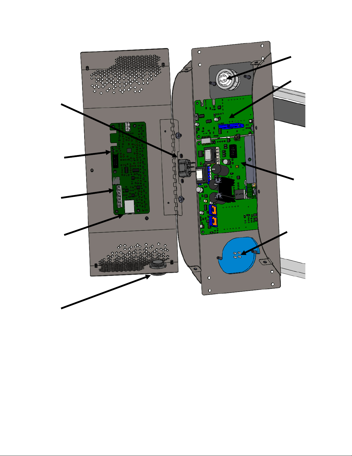
Figure 11 – Main Components
Ozone Lamp
Germicidal
Lamp
Ozone
Daughter
Board
Main Ballast
Board
Control
Board
Power
Entry
Module
Ozone
Controller
Input
Remote/
Serial
RJ45
Connector
Cover
Strain
Relief

17
Troubleshooting
Problem/Symptom
Possible Cause
Solution
No Power
• No power to system
• Fuse blown
• Check main power to system
• Check fuse, replace if blown
Unit Doesn’t Turn on With Airflow
• No airflow present
• Airflow sensitivity needs
adjustment
• Check the HVAC system to ensure
it is supplying airflow
• Adjust the airflow sensitivity
jumper to be more sensitive.
Unit Doesn’t Turn off with no Airflow
• HVAC system is on
• Airflow sensitivity needs
adjustment
• Check the HVAC system to ensure
the airflow is off.
• Adjust the airflow sensitivity
jumper to be less sensitive.
Ozone LED is blinking
• The control board will occasionally
turn off the ozone lamp to reduce
the ozone output. When this
happens the ozone LED will blink.
• This is normal, there is no problem
Ozone LED is not turning on
• No airflow present
• Blue shutdown LED illuminated
• Yellow shutdown LED illuminated
• Red shutdown LED illuminated
• If there is a problem with the ozone
lamp the ozone LED will not
illuminate and the service light will
begin to blink.
• Check the HVAC system to ensure
it is supplying airflow
• Control board is shutting down the
ozone lamp.
• Lamp filaments are damaged,
replace the ozone lamp
• High ambient temperature.
• Replace the ozone lamp
Germicidal LED is not turning on
• No airflow present
• Blue shutdown LED illuminated
• Yellow shutdown LED illuminated
• Red shutdown LED illuminated
• If there is a problem with the
germicidal lamp the germicidal
LED will not illuminate and the
service light will begin to blink.
• Check the HVAC system to ensure
it is supplying airflow
• Control board is shutting down the
germicidal lamp.
• Lamp filaments are damaged,
replace the germicidal Lamp
• High ambient temperature.
• Replace the germicidal lamp

18
Appendix A – Specifications
Power
90-265VAC, 50/60Hz
1.2 – 0.6 A, 180W
Ozone Lamp
185nm Hot Filament, 20,000 hour life
Germicidal Lamp
254nm Hot Filament, 20,000 hour life
Airflow @ 80F
High Sensitivity ~75 ft/minute airflow
Medium Sensitivity ~190 ft/minute airflow
Low Sensitivity ~350 ft/minute airflow
Serial Output
9600 bits per second baud rate
8 bits, no parity
Output Voltage
12V, 0.5A Max
Voltage Input
0-5V, < 0.1mA
Current Input
4-20mA Isolated Circuitry
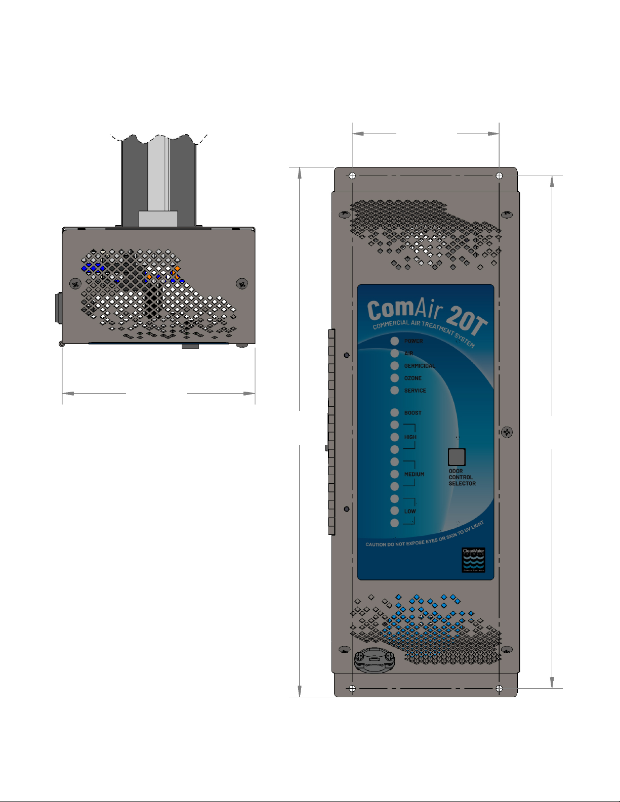
19.3”
(490mm)
16”
(406mm)
3.3”
(84mm)
Appendix A - Specifications
-19-
5.5”
(140mm)
4.3”
(109mm)
15.5”
(394mm)
15”
(381mm)
Table of contents
Other Clear Water Air Cleaner manuals


