Clear Water CD10 Manual
Annual Maintenance Procedure
FOR USE WITH CD10, CD10/AD, CD12 & CD12/AD
ClearWater Tech, LLC. Page 1
1.800.262.0203 • 805.549-9724
850-E Capitolio Way, San Luis Obispo, CA 93401 • email: service@cwtozone.com • www.cwtozone.com LIT228 Rev.100912
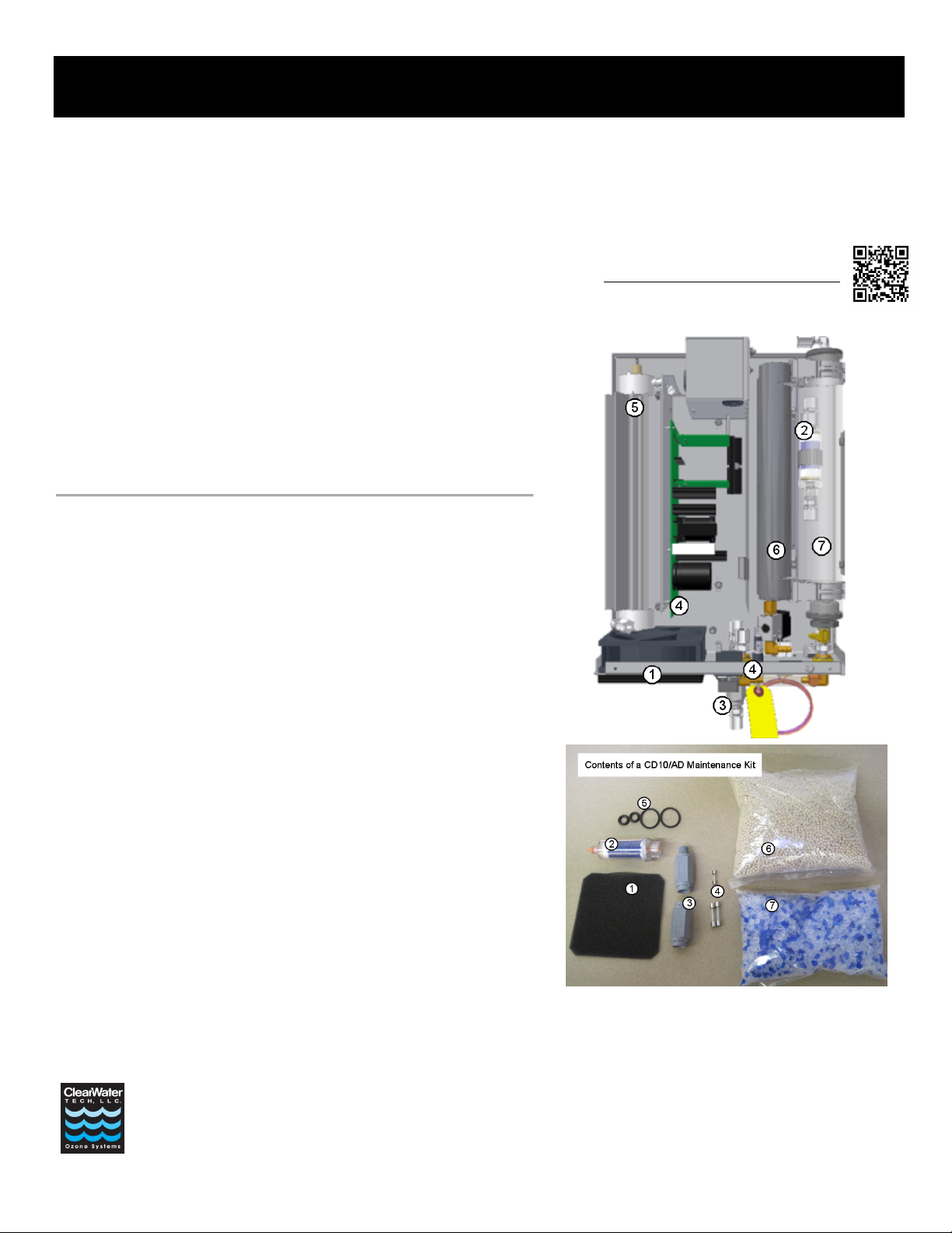
Included in this maintenance kit:
Pictured are the contents of a CD10/AD maintenance kit and an overview image of
the CD10/AD.
Numbered items correspond to descriptions below and their installed locations within
the ozone generator.
CD10, CD12 & CD12/AD systems will have similar maintenance kits and generator
layouts. They will have differences in quantity of parts, however the steps will be the
same.
The CD10 & CD12 kits will not have the media for internal air dryers (#6 & #7).
The CD12/AD kit will not have indicating media (#7)
CD12 & CD12/AD models will have a second set of o-rings (#5), as the units have
two reaction chambers.
Maintenance Will Involve the Following:
1. Cooling Filter: Clean or replace the cooling fan filter elements as required.
2. Inline Particulate Filter: Remove colored protective caps before installing the
new filter. Re-tape threads with Teflon tape. Orientation is universal.
3. Check Valves: Replace both check valves, one at the ozone generator and one at
the injector. Make note of check valve direction before removing old check valve
and reinstall new valve in same direction. Re-tape threads with Teflon tape.
4. Fuses: Save the replacement fuses for use as needed.
5. Reaction Chamber O-Ring Replacement: See page 2 for reaction chamber
maintenance instructions.
6. Air Dryer Media: See page 3 for air preparation maintenance instructions.
7. Indicating Media: See page 3 for air preparation maintenance instructions.
Maintenance of the ozone system is critical to its longevity and operating efficiency. Follow the steps below to perform the
preventative annual maintenance. If you have additional questions regarding the maintenance of your ozone installation, please consult
the operation manual or contact your dealer.
Before you start:
System Shutdown Procedures
Step 1: Turn off power to any peripheral
system hydraulic components and
air prep system.
Step 2: Turn the Main Power switch on the
ozone generator to the “OFF”
position. The LED display on the
front cover should not be
illuminated.
Step 3: Disconnect the power to the ozone
system at the service disconnect
box (if so equipped), main circuit
breaker or by disconnecting the
power cord.
Recommended Tools
Nut Drivers: 5/16”, 11/32”
Screwdrivers: Phillips and flat-head
O-Ring Removal Pick
Hex Key: 7/64”
Marking Pen
Wrench: 5/8” or adjustable
1” Ball hone (optional)
Channel lock-type Pliers
Snap Ring Pliers (for CD10/AD &
CD12/AD)
Cloth Shop Towel
Denatured Alcohol
Teflon Sealing Tape
Video Walkthroughs
Visit our video channel at:
http://www.youtube.com/ClearWaterTech
These, and other procedures are shown.
Annual Maintenance Procedure
FOR USE WITH CD10, CD10/AD, CD12 & CD12/AD
ClearWater Tech, LLC. Page 2
1.800.262.0203 • 805.549-9724
850-E Capitolio Way, San Luis Obispo, CA 93401 • email: service@cwtozone.com • www.cwtozone.com LIT228 Rev.100912
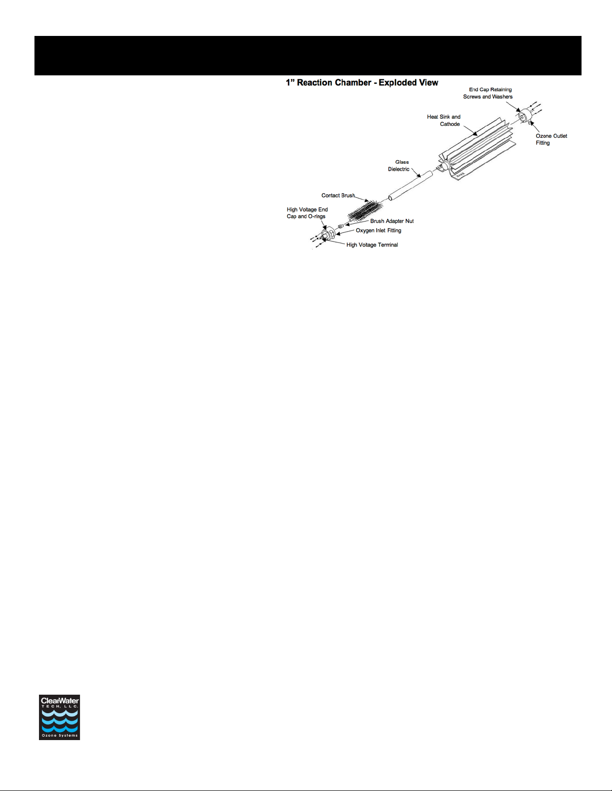
Reaction Chamber Removal and
Disassembly:
Note: Read through all the steps before disassembling the reaction
chamber.
Step 1: Make sure all power to the ozone generator has been
disconnected according to the “System Shutdown Procedures”
outlined above.
Step 2: Disconnect the high voltage lead from the reaction chamber(s).
Step 3: Disconnect the tubing connections on both ends of the reaction
chamber(s).
Step 4: Remove the 4 nuts securing each chamber and remove the
reaction chamber from ozone generator.
Step 5: Make note or mark the position of the end caps and their elbow
fittings on the reaction chambers, during re-assembly the end
caps will need to return to original positions. The orientation of the end caps and the chamber itself is different between the two CD12 chambers.
Step 6: Remove retaining screws and washers from the two end caps (3 each).
Step 7: Using a gentle back-and-forth twisting motion, remove the non-high voltage end cap (the one without the high voltage attachment screw) from the heat
sink/cathode assembly. A flat-head screwdriver may be used to gently pry the end cap off, as long as equal pressure is applied to each side of the end cap.
Step 8: Remove the high voltage end cap and dielectric from the heat sink/cathode assembly.
Step 9: The high voltage end cap can be removed by holding the glass and turning the end cap counter-clockwise approximately 6 turns. Pull the end cap off the glass.
Push the contact brush out of the dielectric glass. A screwdriver can be used to push the brush, and pliers to pull it out once the opposing end is exposed.
Step 10: Inspect the dielectric, end caps and cathode for breakage, corrosion or debris; then follow the assembly and re-installation steps below.
Reaction Chamber Assembly and Re-installation:
Step 1: Remove o-rings from end caps, clean the dielectric glass, end caps and interior of the stainless steel cathode cylinder. Use denatured alcohol, shop towels to
clean and be sure to remove all old o-ring debris. A 1” ball hone can be used to clean the major debris out of the cathode if there is heavy buildup.
Step 2: Prepare the end caps for re-assembly by replacing the o-rings. Thread the hex brush adapter nut, with contact brush attached, onto the end of the high voltage
end cap (cap with the high voltage attachment screw) center screw. Re-tape the threads of the elbow fittings if needed.
Step 3: Using a gentle twisting motion, press the non-high voltage end cap onto the heat sink/cathode assembly until flush with the heat sink cooling fins. Turn the end
cap to the correct orientation.
Step 4: Slide the three end cap retaining screws with washers through the holes in the non-high voltage end cap, aligning them with the heat sink screw bosses. Thread
screws into screw bosses until heads are snug against the end cap.
Step 5: Next we focus on assembling the rest of the subcomponents, before installing them into the reaction chamber. Slowly insert the brush (installed onto the high
voltage end cap) into the dielectric glass. Note: Go slowly in order to prevent or minimize bending the center wire of the brush during this procedure. It is
normal for the bristles to bend flat against the dielectric glass. Fully seat the dielectric glass into the high voltage end cap. Clean the glass with denatured
alcohol once more, and do not retouch the glass without re-cleaning.
Step 6: Hold the reaction chamber upright on a flat surface, empty high voltage side up. Grasp the high voltage end cap and lower the glass into the reaction chamber.
Press directly downwards on the high voltage end cap to fully seat the dielectric assembly; the end caps should be flush with the heat sink cooling fins. Turn
the end cap to the correct orientation.
Step 8: Slide the three end cap retaining screws with washers through the holes in the end cap, aligning them with the heat sink screw bosses. Thread screws into screw
bosses until heads are snug against the end cap.
Step 9: Re-install the complete reaction chamber assembly into the ozone generator by securing the reaction chamber to its mounts, securing delivery line and
connecting the high voltage insulated wire.

Annual Maintenance Procedure
FOR USE WITH CD10, CD10/AD, CD12 & CD12/AD
ClearWater Tech, LLC. Page 3
1.800.262.0203 • 805.549-9724
850-E Capitolio Way, San Luis Obispo, CA 93401 • email: service@cwtozone.com • www.cwtozone.com LIT228 Rev.100912
Air Preparation System
CD10/AD and CD12/AD only: The tan colored beads are an air dryer desiccant. The blue and white media is typically called indicating media. It is silica gel and acts
as an indicator of the health of the air dryers.
If the air dryer desiccant requires replacement, moisture will be present in the dryer’s output. The silica media will absorb the moisture and will change the blue crystals
to pink, then white. If the indicating media has changed color, this maintenance of replacing the media should resolve the issue and restore proper ozone output. If the
indicating media has yet to change color, it is recommended to replace the air dryer media for preventative maintenance. The indicating crystals can be saved for future
use, or installed; it is optional in this case.
For steps regarding replacement of these medias see “Air Dryer Desiccant Replacement” and “Indicating Media Replacement” below.
CD10 and CD12 only: Your air prep system will consist of either a PSA Oxygen Concentrator or LPSA Dry Air. Compressors, PSA Oxygen Concentrator or LPSA
Dry Air: Following the procedures outlined in the compressor rebuild kit, rebuild the two compressor heads and replace all filters.
Note: Manufacturers' recommended interval is 5,000 to 12,000 hours of operation. Compressor performance and/or operating conditions in the equipment area
will dictate the required frequency of this procedure.
Air Dryer Desiccant Replacement
Note: You will need to remove the unit from the wall in order to pour out the media. Allow the air dryer chambers to cool completely and read all steps before
continuing.
Step 1: Straighten out the ends of the dryer chambers using pliers.
Step 2: Using a snap ring tool, remove the top snap rings.
Step 3: Remove the top screens; the o-ring pick is handy for this. The bottom snap ring may be left remaining within the air dryer chambers.
Step 4: Turn the ozone generator over to pour the old sieve material from the dryer chambers and dispose. Note: When removing the sieve material, be sure not to
discard the bottom screens.
Step 5: Re-seat/Re-install the bottom screens. Note: The heater rod must be put through the center of the bottom screens.
Step 6: Fill chamber with new sieve material to 3/4” to 1” below the top of the dryer chambers. You will have more media than needed.
Step 7: Re-install the top screens.
Step 8: Using a snap ring tool, place the top snap rings snug against the top screen.
Step 9: Bend the ends of the dryer chambers in-ward for added retention of the sieve material (optional).
Step 10: The ozone generator must be turned on for 24 hours prior to system start-up to eliminate any moisture trapped in the new sieve material.
Indicating Media Replacement (CD10/AD only)
Step 1: Using wrench, loosen and disconnect the compression fitting located at the top of the indicating media chamber.
Step 2: With a flat-head screwdriver, unlock the two gray clamps securing the indicating media chamber.
Step 3: Pull the chamber free of the clamps, the chamber will only be held within the unit by the bottom cap. Rotate the chamber downwards to position the bottom cap
to be at the top of the chamber.
Step 4: Secure the bottom cap with channel lock pliers and turn the chamber counter-clockwise to unscrew it. Be mindful to not spill the indicating media.
Step 5: Remove the indicating chamber from the unit, remove the interior screen and dispose of the media.
Step 6: Remove the Teflon tape from the bottom cap’s threads and re-tape the threads with 2-3 wraps.
Step 7: Refill the indicating chamber with new blue and white indicating crystals. You will have more media than needed.
Step 8: Replace the interior screen and reinstall the chamber following steps 1 through 4 in reverse order.
This manual suits for next models
3
Table of contents
Other Clear Water Air Cleaner manuals


