ClearFox CU-M User manual

1
Quick Start Guide
ClearFox® Control
Unit CU-M

ClearFox®Control Unit CU-M
2
1TABLE OF CONTENTS
2 Most important information ...................................................................................................... 4
2.1 Switching the device off...................................................................................................... 4
2.2 First start............................................................................................................................. 4
2.3 Login Service Menu............................................................................................................. 4
2.4 Connecting via Wi-Fi / internal webpages .......................................................................... 4
3 Introduction................................................................................................................................ 4
4 Switching the device off.............................................................................................................. 4
5 Warnings / opening of the casing............................................................................................... 5
6 Connecting the consumers (blower, hoses, beacon).................................................................. 5
6.1 Air-SBR................................................................................................................................. 5
6.2 Pump-SBR............................................................................................................................ 6
6.3 One-Tank SBR...................................................................................................................... 6
6.4 Continuous plants (MBBR, Fixed-Bed, …)............................................................................ 6
6.5 Drippling filter (D: Tropfkörper).......................................................................................... 6
7 Connecting to Wi-Fi .................................................................................................................... 7
7.1 Connecting the control unit to the internet via Wi-Fi (ST mode) ....................................... 7
8 Alarm handling............................................................................................................................ 8
9 Process overviews....................................................................................................................... 8
9.1 Air-SBR................................................................................................................................. 8
9.1.1 Process steps.................................................................................................................. 8
9.1.2 Water level measurement ............................................................................................. 9
9.2 Pump-SBR.......................................................................................................................... 11
9.2.1 Process steps................................................................................................................ 11
9.2.2 Selectable output assignment ..................................................................................... 11
9.3 One-Tank SBR.................................................................................................................... 12
9.3.1 Process steps................................................................................................................ 12
9.3.2 Selectable output assignment ..................................................................................... 14
9.4 Continuous plants (MBBR, Fixed Bed, …).......................................................................... 14
9.4.1 Process steps................................................................................................................ 14
9.4.2 Selectable output assignment ..................................................................................... 15
10 Menu......................................................................................................................................... 15
11 Internal webpages .................................................................................................................... 15
12 Transferring the ASW / FW / Web-Pages ................................................................................. 15
12.1 Transfer via Wi-Fi .............................................................................................................. 16


ClearFox®Control Unit CU-M
4
2MOST IMPORTANT INFORMATION
2.1 SWITCHING THE DEVICE OFF
The ClearFox®Control Unit CU-M must not be switched off by disconnecting mains and
batteries. As it works with an operating system and Flash memory, it must be shut down
properly.
Shutting down must be done by pressing the OK button for > 10s. On the LCD a message will
appear. Now the mains connection can be disconnected. That’s it.
2.2 FIRST START
Please mind, that after the first start the plant type must be selected, as the demo software
contains different plant types.
The ClearFox®Control Unit CU-M will restart then, which will take some 2-3min.
2.3 LOGIN SERVICE MENU
The Service PIN is 1111.
2.4 CONNECTING VIA WI-FI /INTERNAL WEBPAGES
- SSID: WWTP-Controller
-Wi-Fi password: 12345678
-IP address (must be entered into the browser address line (=where you’d type
www.google.com): http://192.168.117.1/
oUsername for service login: service
oPassword: 1111 (same as service menu PIN)
3INTRODUCTION
The ClearFox®Control Unit CU-M platform is a powerful, free programmable control unit for
decentralized STP.
The IoT platform is equipped with a Wi-Fi module (access point (AP) and station mode (ST), even
parallel) and an integrated webserver. Thus, the Sequetrol® IoT can be either operated via the
LCD + menu or via any web browser (smartphone, tablet, PC). An internet connection is not
required. The Wi-Fi of the control unit creates a local hotspot (in access point mode).
More information about the IoT platform can be found on our webpages.
4SWITCHING THE DEVICE OFF
The ClearFox®Control Unit CU-M must not be switched off by disconnecting mains and
batteries. As it works with an operating system and Flash memory, it must be shut down
properly.
Shutting down must be done by pressing the OK button for > 10s. On the LCD a message will
appear. Now the mains connection can be disconnected. That’s it.

ClearFox®Control Unit CU-M
5
5WARNINGS /OPENING OF THE CASING
To gain access to the screw-type terminals, the service compartment of the casing must be
opened by unscrewing the two cross slot screws marked with the red circles in Figure 1.
Figure 1: Opening the casing of the Sequetrol® IoT midi
This kind of operation may only be carried out by trained staff, since there are live
components carrying 230V mains voltage under the cover (at the underside of the printed
circuit board and close to the mains supply connectors and the fuse, mains voltage 230 V.)
Before removing the casing cover, it is necessary to pull the mains supply connector!
6CONNECTING THE CONSUMERS (BLOWER,HOSES,BEACON)
6.1 AIR-SBR
-Blower: Connected to the electric socket of the ClearFox®Control Unit CU-M.
-Valves:
oFilling: Out 2
oClearwater removal / Discharge: Out 3 –either valve or submersible pump (can
be selected via the web pages)
oSludge return: Out 4
oAeration / Denitrification: Out 5
-BonFlash alarm beacon is connected to the terminals marked with BF-C (brown cable)
and GND (white cable), (see chapter 5).

ClearFox®Control Unit CU-M
6
-Overfill Float Switch: Optional. Connected to the digital input terminal DI1 inside the
controller (see chapter 5).
6.2 PUMP-SBR
Output functions can be selected via web pages.
-Blower (+Valve) / Injection Aerator: Connected to the electric socket of the
ClearFox®Control Unit CU-M (+Out 5) / electric socket.
-Pumps / Valves:
oFilling: Direct submersible pump - Out 2; using the Sludge Pump –Sludge Pump
–Out 4
oClearwater removal: Pump Out 3 / Valve Out 3 (+Blower)
oSludge return: Pump Out 4 / Valve Out 4 (+Blower)
-BonFlash alarm beacon is connected to the terminals marked with BF-C (brown cable)
and GND (white cable), (see chapter 5).
-Overfill Float Switch: Optional. Connected to the digital input terminal DI1 inside the
Sequetrol® IoT (see chapter 5).
6.3 ONE-TANK SBR
Output functions can be selected via web pages.
-Blower (+Valve) / Injection Aerator: Connected to the electric socket of the
ClearFox®Control Unit CU-M (+Out 5) / electric socket.
-Sludge return: Pump Out 3 / Valve Out 3 (+Blower)
-BonFlash alarm beacon is connected to the terminals marked with BF-C (brown cable)
and GND (white cable), (see chapter 5).
-Overfill Float Switch: Optional. Connected to the digital input terminal DI1 inside the
ClearFox®Control Unit CU-M (see chapter 5).
6.4 CONTINUOUS PLANTS (MBBR, FIXED-BED,…)
Output functions can be selected via web pages.
-Blower (+Valve): Connected to the electric socket of the ClearFox®Control Unit CU-M
(+Out 5)
-Pumps / Valves:
oFilling: Submersible pump - Out 2 / Airlift –Out 2 (+Blower)
oClearwater removal: Pump Out 3 / Valve Out 3 (+Blower)
oSludge return: Pump Out 4 / Valve Out 4 (+Blower)
-BonFlash alarm beacon is connected to the terminals marked with BF-C (brown cable)
and GND (white cable), (see chapter 5).
-Overfill Float Switch: Optional. Connected to the digital input terminal DI1 inside the
ClearFox®Control Unit CU-M (see chapter 5).
6.5 DRIPPLING FILTER (D: TROPFKÖRPER)
Work in progress…

ClearFox®Control Unit CU-M
7
7CONNECTING TO WI-FI
The ClearFox®Control Unit CU-M can be operated and monitored via Wi-Fi. All
settings can be done comfortably in your browser (smartphone, tablet, PC).
- SSID: WWTP-Controller
-Wi-Fi password: 12345678
-IP address (must be entered into the browser address line (=where you’d type
www.google.com): http://192.168.117.1/
oUsername: service
oPassword: 1111 (same as service menu PIN)
In case these parameters shall be changed, please refer to the Network Settings page:
Figure 2: Wi-Fi - Access Point settings
Please do not forget to push Apply Wi-Fi Settings (control unit restarts).
The ClearFox®Control Unit CU-M can run Wi-Fi in Access-Point (AP) and in Station Mode (ST)
- AP: Wi-Fi hotspot without internet connection (intranet only)”
- ST: Connection to another Wi-Fi hotspot or router (e.g. your company Wi-Fi), often used
to connect the Sequetrol® IoT to the public internet (e.g. for telemetry)
7.1 CONNECTING THE CONTROL UNIT TO THE INTERNET VIA WI-FI (ST MODE)
The control unit can be run simultaneously in Access Point (AP) and Station (ST) mode.
-Access Point mode means, the control unit behaves as a “Wi-Fi hotspot”. You can
connect with any device and view the internal webpages.
-Station mode means, the control unit connects to another Wi-Fi network (mostly with
internet access).

ClearFox®Control Unit CU-M
8
The necessary setting can be set performed on the Network Settings page:
Figure 3: Wi-Fi - Station Mode settings
If DHCP is activated (recommended), only the SSID and the Wi-Fi Password must be entered.
Please do not forget to push Apply Wi-Fi Settings (control unit restarts).
8ALARM HANDLING
The ClearFox®Control Unit CU-M monitors different alarm states like blower pressure and
overfill alarm.
All alarms can be acknowledged by pressing <OK> short. Acknowledging the alarm deactivates
the Buzzer and the BonFlash output. The red LED remains on, and the last alarm remains in the
Status Screen, until the reason for the alarm is gone (e.g. float switch is down again) or until the
alarm is deleted.
The alarm will be deleted automatically when the alarm reason disappears. It can also be
deleted by pressing <OK> for 1-2s or via the web pages. Please mind that if the alarm reason is
still active, the alarm will reappear.
9PROCESS OVERVIEWS
Please note that these are demo / sample programs. They can either be completely replaced by
your process, menu, and web pages. Or we can adopt these programs to your requirements and
preferences.
9.1 AIR-SBR
9.1.1 Process steps
-Normal mode

ClearFox®Control Unit CU-M
9
oLevel measurement via Filling. If below switching level 1 => eco
oFilling
oLevel measurement via Filling. If above switching level 2 => overfill alarm
oDenitrification (can be deactivated by setting step time to 0s)
oAeration
oSludge (before Settling, option, can be deactivated by setting step time to 0s) –
sludge return will not take place within the first 90 days after bringing into
service. This value can be changed, the parameter is called Biology Build-Up
Time.
oSettling
oSludge (after Settling, option, can be deactivated by setting step time to 0s) –
sludge return will not take place within the first 90 days after bringing into
service. This value can be changed, the parameter is called Biology Build-Up
Time.
oClearwater removal
oOption: Check DI1, if closed => overfill alarm (if no float switch is connected,
there will not be an alarm)
- Eco mode
oAeration
oLevel measurement via Filling. If above switching level 1 => normal
oEach 6 eco cycles (frequency can be changed) => At least one normal mode
9.1.2 Water level measurement
Water level measurement at this process is performed using the filling airlift in the pretreatment
tank.
If the level before filling is higher than the calibrated value plus Offset 1, filling will be
performed, and the control unit will follow the normal mode program. If the level is lower, filling
will not be performed, and the program follows the eco mode process.
If the level after filling is higher than the calibrated value plus Offset 2, this means, filling could
not be performed. Likely the problem was that the reactor is (still) full because clearwater
removal did not work and thus the water pumped from the pretreatment to the reactor during
filling simply flowed back. An overfill alarm will be signalized in this case.
calibrated minimum
Offset 1
(Eco / Normal)
Offset 2
(overfill alarm)
Figure 4: Pretreatment tank with filling airlift and calibrated minimum, Offset 1 and 2

ClearFox®Control Unit CU-M
10
To be able to run the water level measurement, the “calibrated minimum” must be calibrated
(takes place automatically 14-days after bringing into operation, see chapter 9.1.2.1).
9.1.2.1 Automatic calibration
If ClearFox®Control Unit CU-M is simply installed to a plant, the automatic calibration will be
performed after 14 days. This delay shall ensure, that the pretreatment tank is filled at least to
the minimal level of the filling airlift and the reactor is filled at least to the minimal level for the
sludge return airlift.
After these 14 days, this process will be performed:
1) Clearwater removal
2) Filling with longer filling time to make sure that the level in the pretreatment is pumped
down to the minimum that can be reached using the filling airlift. The filling airlift now
“slurps” (does not pump properly, anymore, as it cannot suck anymore water).
3) “Sludge return” for some 60s to increase the level in the pretreatment so that the filling
airlift can pump properly, again.
4) Filling for 20s –the pressure at this minimal water level will now be stored as “calibrated
minimum”.
Now the ClearFox®Control Unit CU-M is able to measure the water level in the plant.
9.1.2.2 Manual calibration
In case the automatic calibration shall not be used for any reason, for example because the level
measurement shall be tested “instantly” (not after 14 days), the calibration can also be
performed manually. The manually entered values will not be overwritten by automatic
calibration.
To do so, the user must empty the water level in the pretreatment until there is only some 0.5-
1cm of water above the inlet of the filling airlift (the airlift must still be able to pump properly,
no slurping or sucking air). Now the filling airlift is activated in the manual control menu or web
page. The displayed pressure must now be noted. This pressure can now be entered in the
“Minimum” text field:

ClearFox®Control Unit CU-M
11
Figure 5: Parameters for water level measurement in the web pages of the IoT control unit
9.1.2.3 Changing the levels for Normal- / Eco-Mode and Overfill Alarm
The offsets can be changed in the web pages (Pressure measurement / Calibration, see Figure 5)
or in the Service Menu / Pressure.
9.2 PUMP-SBR
9.2.1 Process steps
- Normal mode
oFilling
▪Via dedicated pump: ON (15min) or until DI1=closed. On timeout (step
time over, DI1=open) => Eco
▪Via Sludge Pump: ON (10s)+OFF (14:50min) or until DI1=closed. On
timeout (step time over, DI1=open) => Eco
oDenitrification (0:40min ON / 9:20min OFF / 60min Total)
oAeration (8min ON / 12min OFF / 9.5h Total)
oSludge (before Settling) (2min)
oSettling (1.5h)
oSludge (after Settling) (0min)
oClearwater removal (20min)
oCheck DI1, if closed => overfill alarm. Else, continue
- Eco mode
oAeration (2min ON / 8min OFF / 8:45h Total)
oFilling (only ON (15min) at “Pump”, ON (10s)+OFF (14:50min) at “via Sludge
Pump”). If DI1=closed => Normal, on timeout (step time over, DI1=open) =>
continue Eco
oEach 6 cycles => Normal mode
9.2.2 Selectable output assignment
FUNCTION/
SELECTABLE

ClearFox®Control Unit CU-M
12
OPTION AND
CONSEQUENCE
FILLING
Pump
Out 2
Current limits for pump
(300/1800mA) applied
Via sludge pump (Out 4)
Current limits for pump
(300/1800mA) applied
Instead of pumping only 10s + pause
(adjustable)
AERATION
Blower (+ valve)
Out 1 (+ 5)
Current limits for Blower
(250/900mA)+ valve (50/150mA)
applied
Generic pressure limits (7/350mbar)
for Blower applied
Injection aerator
Out 1
Current limits for aerator
(300/2500mA) applied
SLUDGE
Blower + valve
Out 1 + 4
Current limits for Blower
(250/900mA)+ valve (50/150mA)
applied
Generic pressure limits (7/350mbar)
for Blower applied
Via sludge pump (Out 4)
Current limits (300/1800mA) for
pump applied
CLEARWATER
Blower + valve
Out 1 + 3
Current limits for Blower
(250/900mA)+ valve (50/150mA)
applied
Generic pressure limits (7/350mbar)
for Blower applied
Pump
Out 3
Current limits (300/1800mA) for
pump applied
9.3 ONE-TANK SBR
9.3.1 Process steps
For the level measurement (overfill alarm) a manual calibration must be performed. In case this
calibration was not performed (yet), there will be no overfill alarm.
RTC sync for beginning of settling phase can be set (mostly around 3am).
Number of cycles per day can be set (1-4).
Holiday period (number of days can be entered that is counted down) can be entered, where the
controller uses different ON/OFF times for the aeration.
Cycle 1 of the day (also for bringing into operation) has a different Aeration step.
Aeration
- first cycle of the day: Infinite until RTC sync time reached
- next cycles of the day: Infinite until total Aeration Total Time (calculated out of
cycles per day and the remaining step times) reached
Aeration 1 (6min ON / 14min OFF) –via valve on Out 5 –primary aeration of the reactor
after one ON/OFF cycle jump to
ClearFox®Control Unit CU-M
13
Aeration 2 (4min ON / 6min OFF) –via valve on Out 4 –optional aeration of another part of
the reactor or the sludge tank.
after one ON/OFF cycle jump to Aeration 1
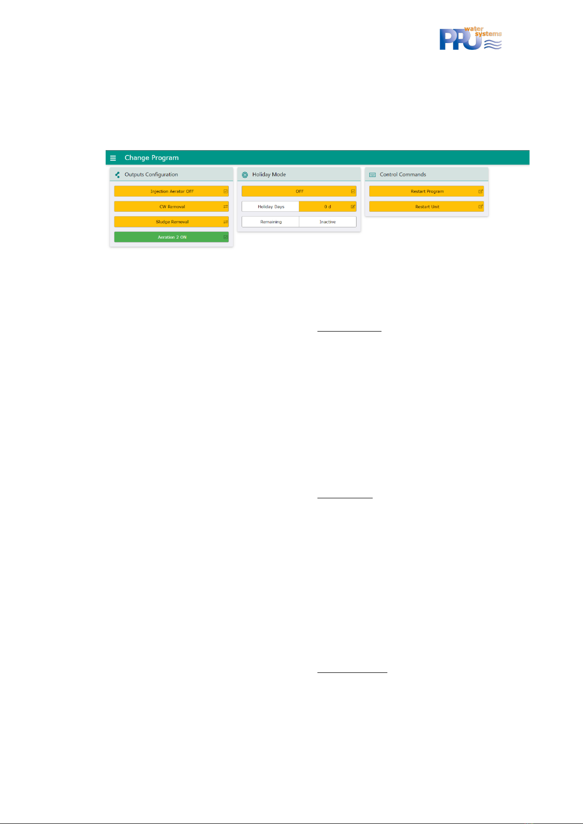
If Aeration 2 shall not be used, it can be deactivated via the web pages:
Figure 6: One-Tank SBR program individualization via internal web pages
Sludge return
Time taken from the settling time –example: Settling = 2h, sludge = 2min => settling will be
1:58h in reality and sludge 2min –sludge return before settling can be deactivate via a
parameter via the Patch file (please ask PPU in case you want to deactivate it). All sludge
returns have the same step times.
Max. step duration that can be entered is 30min., default step duration is 0min (!)
Settling (1.5h)
OPTIONAL Sludge return
This sludge return can be activated via a parameter via the Patch file (please ask PPU in
case you want to activate it)
Time taken from the settling time –example: Settling = 2h, sludge = 2min => settling will be
1:58h in reality and sludge 2min –sludge return after settling can be deactivate via a
parameter via the Patch file. All sludge returns have the same step times.
Max. step duration that can be entered is 30min., default step duration is 0min (!)
Clearwater removal
Max. step duration that can be entered is 1h., default duration is 15min
OPTIONAL Sludge return
This sludge return can be activated via a parameter via the Patch file (please ask PPU in
case you want to activate it)
Time taken from the settling time –example: Settling = 2h, sludge = 2min => settling will be
1:58h in reality and sludge 2min –sludge return after clearwater can be deactivate via a
parameter via the Patch file. All sludge returns have the same step times.
Max. step duration that can be entered is 30min., default step duration is 0min (!)
Water level measurement
Via CW (only if calibrated!) –must be below “calibrated value + offset”. Else overfill alarm.

ClearFox®Control Unit CU-M
14
In parallel via digital input 1 –if up after CW-Rem. => overfill alarm.
9.3.2 Selectable output assignment
FUNCTION/
SELECTABLE OPTION
AND CONSEQUENCE
AERATION
Blower (+ valve)
Out 1 (+ 5)
Current limits for Blower
(250/900mA)+ valve (50/150mA)
applied
Generic pressure limits
(7/350mbar) for Blower applied
Injection aerator
Out 1
Current limits for aerator
(300/2500mA) applied
Offset and calibrated value for
overfill = 0mbar
AERATION 2
(OPTION)
Blower (+ valve)
Out 1 (+ 4)
Current limits for Blower
(250/900mA)+ valve (50/150mA)
applied
Generic pressure limits
(7/350mbar) for Blower applied
NO
SLUDGE
Blower + valve
Out 1 + 3
Current limits for Blower
(250/900mA)+ valve (50/150mA)
applied
Generic pressure limits
(7/350mbar) for Blower applied
Via sludge pump (Out 3)
Current limits for pump
(300/1800mA) applied
CLEARWATER
Blower + valve
Out 1 + 2
Current limits for Blower
(250/900mA)+ valve (50/150mA)
applied
Generic pressure limits
(7/350mbar) for Blower applied
Pump
Out 2
Current limits for pump
(300/1800mA) applied
9.4 CONTINUOUS PLANTS (MBBR, FIXED BED,…)
9.4.1 Process steps
RTC sync for day/night mode. Beginning and end of the night period can be changed. During
night other ON/OFF times can be applied for the particular outputs than during the day.
Holiday period (number of days can be entered that is counted down) can be entered, where the
controller uses different ON/OFF times for the particular outputs.
For functions (Filling, Aeration, Sludge, Clearwater) the ON/OFF times for day, night and holiday
operation can be set. If ON time = 0s, the output is deactivated. If OFF time = 0s, the output is
permanently on.
Overfill alarm via digital input 1 (e.g., float switch).

ClearFox®Control Unit CU-M
15
9.4.2 Selectable output assignment
FUNCTION/
SELECTABLE OPTION
AND CONSEQUENCE
FILLING
(ON DAY/OFF DAY //
ON NIGHT/OFF
NIGHT // ON
HOLIDAY / OFF
HOLIDAY)
Pump
Out 2
Current limits for pump
(300/1800mA) applied
Airlift
Out 1 + 2
Current limits for Blower
(250/900mA)+ valve (50/150mA)
applied
Generic pressure limits
(7/350mbar) for Blower applied
AERATION
(ON DAY/OFF DAY //
ON NIGHT/OFF
NIGHT // ON
HOLIDAY / OFF
HOLIDAY)
Blower (+ valve)
Out 1 (+ 5)
Current limits for Blower
(250/900mA)+ valve (50/150mA)
applied
Generic pressure limits
(7/350mbar) for Blower applied
-
SLUDGE
(ON DAY/OFF DAY //
ON NIGHT/OFF
NIGHT // ON
HOLIDAY / OFF
HOLIDAY)
Blower + valve
Out 1 + 4
Current limits for Blower
(250/900mA)+ valve (50/150mA)
applied
Generic pressure limits
(7/350mbar) for Blower applied
Via sludge pump (Out 4)
Current limits for pump
(300/1800mA) applied
CLEARWATER
(ON DAY/OFF DAY //
ON NIGHT/OFF
NIGHT // ON
HOLIDAY / OFF
HOLIDAY)
Blower + valve
Out 1 + 3
Current limits for Blower
(250/900mA)+ valve (50/150mA)
applied
Generic pressure limits
(7/350mbar) for Blower applied
Pump
Out 3
Current limits for pump
(300/1800mA) applied
10 MENU
PPU used its “standard menu” for the sample.
PPU assumes, that the menu is mostly self-explaining. For questions, please do not hesitate to
contact us via [email protected].
11 INTERNAL WEBPAGES
PPU used its “standard webpages” for the sample.
PPU assumes, that the webpages are mostly self-explaining. For questions, please do not
hesitate to contact us via [email protected].
12 TRANSFERRING THE ASW /FW /WEB-PAGES
The ASW, FW and the web pages can be transferred by USB or Wi-Fi.

16
ClearFox®Control Unit CU-M
12.1 TRANSFER VIA WI-FI
Please mind that the batteries must be connected.
Please
- connect to the Wi-fi of the Sequetrol® IoT
- open the webpage http://192.168.117.1/
- login as serviceman
- go to FW & ASW Update
- select the *.pkg (Pack) file that you have received from PPU here:
- click on Start update process
- done!
12.2 TRANSFER VIA USB
Please mind that the batteries must be connected.
Please record the *.pkg (Pack) file into the root folder of a common USB stick formatted with
FAT16 or FAT32 (NOT NTFS).
a. Shut-off the control unit (see chapter 0)
b. insert the USB stick
c. connect the control unit to mains and to have the batteries connected.
d. Follow the instructions on the LCD
Some (cheap) USB sticks might not be recognized. In that case please use a brand stick.
Table of contents
Popular Control Unit manuals by other brands

Moen
Moen M-CORE U130CI installation guide

Motorline professional
Motorline professional MC102 User& installer's manual

HYDAC International
HYDAC International FMMHP Operating and maintenance instructions

Fanstel
Fanstel BlueFan BT680E manual

iNels
iNels EST-2 Series Manual instructions

Lincoln industrial
Lincoln industrial MP1 owner's manual


Siemens
Siemens TRI-S installation instructions

INOXPA
INOXPA INNOVA F Installation, service and maintenance instructions

Burkert
Burkert 6213 EV operating instructions

Vimar
Vimar ELVOX SL230.T Connection and operating manual

Eaton
Eaton 11 Series Installation and start-up guidelines

Gantner
Gantner E Series Communications guide