NOTE: If you select a button other than the nº 2 for pedestrian opening, the control
board will recognize it as complete opening button, which means it will override the
first pressed button. If the pedestrian opening is not wished, do not press the nº2
button and wait for the CODE LED to turn off.
8 ▷ The transmitter is now configured.
NOTE: After setting up a transmitter type, the control board will only accept transmit-
ters from the same type, it means, if the first transmitter is Rolling Code, they must all
be Rolling Code for the central to accept them.
To program other transmitters, repeat the steps from nº6.
▷ Erase all the transmitters from the control board
1 ▷ With the gate closed, hold the P1 button continuously.
The CODE LED lights up and wait for 15 seconds until it turns o.
Release the P1 and the LED will flash twice that signals the MEMORY RESET sucess.
▷ Programming the Working Time and Engine’s Pause
1 ▷ With the gate closed, place the dipper 9 to "ON", press transmitter (already
programmed) / START and the gate will start to open.
2 ▷ When the gate stops at the open position (opening limit-switch is enabled), wait
for the desired pause time (*) and give a new START to close. This waited time
represents the time that the engine will wait between the end of the opening maneu-
ver and the the automatic closure’s start. This automatic closure will only happen if the
4 and 5 dippers are in the selected positions to activate it (see page 03).
When the gate reaches the closed position, change the Dipper 9 to OFF to finish
programming and CODE LED will blink and go o. If the dipper is leaved ON, the
programming won’t be finalized.
▷ Total Opening and transmitter programming:
1 ▷ Place all the dippers in OFF position
(down). In case of not using safety device
at 4/M2 terminal (ex:photocells), place
the dipper 8 in ON to disable it.
2 ▷ Unlock the engine, place the gate in
the middle position and re-lock the
engine.
3 ▷ Connect the power to the control
board check if the limit-switches are
activated correctly.
When wiring the limit-switches at 01 and
02 terminals, the FCH and FAP LEDs will remain lit. When moving the spring manually
towards closing position, the FCH LED must turn o and when moving it towards
opening position, the FAP LED must go o too. If the LEDs are turning o switched
(FCH for opening and FAP for closing), swap the wires from 01 and 02 terminals.
4 ▷ Make a START with a help of a wire by connecting the 3 and 7 terminals with the
wire tips and check if the motor is running in the correct direction. When the gate
starts moving to one side, move the limit-switches spring towards the gate’s move-
ment direction and it should stop. If it doesn’t, pull it the other way and it will stop.
Swap the motor wires (13 and 15 terminals from M1 connector) to put in the right direc-
tion.
5 ▷ When the gate is synchronized with the limit-switch correct direction, make a
START again between 3 and 7 terminals. The gate will begin to move to one side. Let it
reaches the closed position electrically.
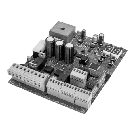
6 ▷ When the gate comes to a closed position, press the P1 button located on the
control board for 2 seconds until the CODE LED (see connection diagram page 07.A)
stays lit. Right away, press the transmitter button you want to be the total opening
key (choose between 1, 3 and 4 buttons shown in the images at the right).
NOTE: When the transmitter button is pressed, the CODE LED must blink, indicating
it is receiving the code.
7 ▷ Release the first button and then press the button number 2 to memorize the
pedestrian opening button. Release it and wait for the CODE LED turns off.
All tests must be performed by skilled technicians due to serious danger
associated with the misuse of electrical systems!
To detect which components have problems during an sliding automatism installation,
sometimes is necessary to conduct tests with a direct connection to a 230V power
supply. For this, is necessary to interpose a capacitator on the connection to the motor
can work (check the capacitor type to be used in the product manual).
In the diagram below is shown how this connection must be made and how to merge
the different component wires.
NOTES:
▷ To perform the tests its not needed to remove the automatism from the place,
because this way you can understand if the automatism, directly connected to the
power, can function correctly.
▷ The order of capacitator wires linked with the automatism wires are not important,
as long as the wires stay linked, one to the Brown wire and the other to the Black.
▷ The common must always be connected to the power supply.
▷ To reverse the automatism functioning direction, swap the Black wire with the
automatism Brown wire.
04. CONFIGURATINON
▷INSTALLATION PROCESS CAPACITATOR SCHEME ◁
05.COMPONENT TEST
05.A 05.B
If the control board blocks and a RESET is needed, follow these steps:
1 ▷ Turn o the control board’s power.
2 ▷ Put Dipper 9 to ON.
3 ▷ Reconnect the control board to the power supply and put the dipper 9 to OFF.
▷ Programming the Pedestrian Work Time
1 ▷ With the gate in closed mode put the Dipper 9 ON.
2 ▷ Press the button nº2 to start opening the gate. Upon reaching the desired
position, press again the button to stop the engine. Wait the desired pause time and
give a new START to close. This waited time represents the time that the engine will
wait between the end of the pedonal’s opening maneuver and the the automatic
closure’s start. Nearing the limit-switch’s end, the engine will stop.
3 ▷ The setting is completed, place the dipper 9 in OFF to finalize and close the
pedestrian programming.
▷ Force and Sensitivity Regulation (anti-crushing)
The control board has 2 trimmers (rotary knobs):
RV1 - Allows the engine sensitivity regulation (increases sensitivity by
rotating it in the clockwise direction);
RV2 - Allows the engine power regulation (increases the force by rotating in
the clockwise direction );
Warning: To use anti-crush function (recommended for small gates), it is necessary to
regulate first the engine’s power with the trimmer RV2 and right after the sensitivity
with trimmer RV1.
If you change the engine’s power after performing a Working Time and Engine Pause
programming , a new one is going to be needed.
▷ Iluminated Lightbulb in Pause Time (10 and 11 terminals)
1 ▷ If you wish to activate this function, when programming work time and engine’s
pause (page 04.B), at the point 2, do the following operation from (*).
▷Press the pedestrian transmitter button while the gate is paused, between the
opening and closing.
NOTE: In case of using the 11 and 12 terminals for the lightbulb, the DIP3 must be OFF
and the Lightbulb must have a circuit board to make the lamp to blink.
230V POWER
SUPPLY
AUTOMATISM
FOR SLIDING
GATES
CAPACITATOR
Ground wire
Common(Blue)
Black
Brown
