manuals.online logo
Brands
  1. Home
  2. •
  3. Brands
  4. •
  5. ClearSpan
  6. •
  7. Lawn And Garden Equipment
  8. •
  9. ClearSpan PREMIUM COMBO PB02804R4N User manual

ClearSpan PREMIUM COMBO PB02804R4N User manual

PREMIUM COMBO
BUILDINGS
# PB02804R4N
20’ Wide x 32’ Long
INSTRUCTIONS
©2005 ClearSpan™
All rights reserved. Reproduction prohibited without permission.
Revision Date: 3-29-05
2
Introduction
Thank you for purchasing the ClearSpanTM Poly Shelter. We appreciate your
patronage. We hope you enjoy building and utilizing your shelter. Please read
this entire instruction manual before starting to assemble your shelter. If you
require assistance during the construction process you may call us at 1-800-245-
9881.
A Word About Safety
Just as we want you to be pleased with your assembled shelter, we don’t want
you to get hurt in the process of building it! Our suggestions include the following:
• Wear eye protection when drilling and power-screwing.
• Wear head protection when working with/under heavy parts including metal-
tubing.
• Wear gloves when handling metal tubing due to sharp or rough ends.
• Use a portable GFCI when working with corded power tools.
• Never erect a shelter directly under power lines.
• Be careful not to drive anchors into buried power cables.
• Do not climb on the shelter or its frame. It is not designed to support human
weight.
• If the shelter is enclosed, provide proper and adequate ventilation.
• Do not store hazardous materials in the shelter without proper ventilation and
precautions.
• If both ends are covered, provide proper ingress and egress to prevent
entrapment.
• Do not occupy the shelter during very high winds, hurricanes, or tornadoes.
• If shelter is moved after construction, inspect shelter thoroughly before reuse.
• Use common sense at all times.
Selecting a Location
It is important to select a proper location for your poly shelter. While the location
may have been predetermined before you even ordered your shelter, you may
want to “improve” the location before starting the assembly process.
One of the most important considerations is that the location should be level. If it
is not, the shelters frame will not assemble or sit properly. If your location is not
level, you should consider grading it before building on it. Another alternative is to
provide footings, which are level to support the shelter.
These could be pressure-treated posts, pre-cast concrete blocks, or poured in
place footings.
Drainage is another important consideration. Rain flowing off your shelter should
have a natural path to flow away from the shelter and not under or into it.
3
20GGS15A
Position A
QUANTITY: 9
20GGS15B
Position B
QUANTITY: 9
S15P075
1.50” SQ. TUBE PLAIN
QUANTITY: 9
S15P062
1.50” SQ. TUBE PLAIN
QUANTITY: 2
S15P0805
1.50” SQ. TUBE PLAIN
QUANTITY: 4
S15S099
1.50” SQ. TUBE SWAGED
QUANTITY: 31
S15P0272
1.50” SQ. TUBE PLAIN
QUANTITY: 1
S15P072
1.50” SQ. TUBE PLAIN
QUANTITY: 9
S15P071
1.50” SQ. TUBE PLAIN
QUANTITY: 2
S15P040
1.50” SQ. TUBE PLAIN
QUANTITY: 1
131P0255
1.315” PIPE PLAIN
QUANTITY: 7
131S075
1.315” PIPE SWAGED
QUANTITY: 58
131P043
1.315” PIPE PLAIN
QUANTITY: 4
S15P009
1.50” SQ. TUBE PLAIN
QUANTITY: 1
104643
MIDDLE CONNECTOR
QUANTITY: 2
104641
SQ. INTRESECTION CONN.
QUANTITY: 9
QH1070
1.315” PURLIN PIPE STRAP 1”
QUANTITY: 65
QH1330
GABLE FRAME BRACKET
QUANTITY: 4
FA4482
#14 x 1” TEK SCREW
QUANTITY: 400
100441
3/8” NUT SETTER
QUANTITY: 1
PARTS INDENTIFICATION
(NOTE: NOT ALL PARTS LISTED ON SPEC SHEET ARE LISTED ON THE
PARTS ID PAGE)
4
104624
SQ. FITTING 1-WAY
QUANTITY: 11
104626
SQ. FITTING 3-WAY
QUANTITY: 10
104625
SQ. FITTING 2-WAY
QUANTITY: 6
QH1061
1” x 4000-LB. RATCHET
QUANTITY: 11
104212
H-Channel 8ft.
QUANTITY: 19
104213
U-Profile 8ft.
QUANTITY: 12
104548
End Cap 8ft.
QUANTITY: 12
FAH325
5/16” x 5” CARRIAGE BOLT
QUANTITY: 4
FALB02b
5/16”-18 NUT
QUANTITY: 4
LJ7510
DUCT TAPE
QUANTITY: 1
FAMF01b
1/4” x 1” WASHER
QUANTITY: 200
Section A - Unpack & Identify Parts
Step 1: Before you begin to assemble your shelter you should first unpack the
contents of your shipment. During this process you will learn what all of the
various parts look like.
Step 2: Carefully go through the bill of material that came with your shelter and
verify that you have all the required parts.
Same process is applied to Square Tube
Connections.
ANY SHARP OR ROUGH EDGE SHOULD HAVE SUPPLIED DUCT TAPE
COVERED OVER IT SO AS TO NOT DAMAGE THE COVER.
This includes-
Cover conduit screw heads
Tek screw heads that hold down inside of cover
Ends of cover conduit pipe
5
Main Base Construction-
The roll-up door assembly has (2) 2” square anchored pipe for its base. These
pipes will be encased in concrete (provided by buyer) in order to assure extra
stability.
NOTE: Be EXTREMELY mindful where you place the (2) concrete anchors. The
entire building will be based from those anchors. The concrete should be set 4”
below ground level; this way the door will be shut tightly against the ground, and
not the concrete anchors.
Needed-
(2) 2” Sq. tubes 18”L
(1) 1.5” sq. tube 9”
(2) 104624 connector
(2) 104625 connector
Ground plane
Inside of pipe distance = 96”
6
Allow the top of the 2” anchor pipes to be flush with ground level.
NOTE: Concrete must be FIRM before proceeding. Be sure to check anchor
placement with a level before concrete is set.
(2) 104626 connectors will be placed into the anchor pipes in the direction shown
above. Fasten the pipe to the connector with 1” Tek Screws.
The other two pipes consist of the following
(1) 1.5” sq. tube 9” L
(1) 1.5” sq. tube 27.25” L
Place pipe into connectors as shown above. (2) 104625 connectors will be
added to the end wall pipes. Fasten with Tek screws.
End frame assembly-
Parts needed-
(3) 2” sq. tube 96” L
(1) 2” sq. tube 72” L
(1) 2” sq. tube 20” L
(2) 104626 connectors
NOTE: the 104626 connectors are inside the intersection of the corner pipe. Be sure
to fasten with Tek screws FROM THE INSIDE of the building. Pipe will be added
7
to the outside of the frame on both sides. In order to be flush, no Tek Screws can be
on the sidewalls of the pipe. Detail below.
There will be a splice pipe
added to the exterior of the
frame pipe. No Tek screws
can be added on this face
when securing the connector
inside.
Base connector assembly-
(2) connectors need to be added before base assembly can be completed.
Leave approximately 9 ½” of space between the outside edge of the frame pipe
and the 104624 connector. These two connectors will go on the 27 ¼” pipe. The
horizontal connector- pointing towards the inside of the building- will line up
directly with the vertical connector. Detail below.
(2) 104624 placement
8
Rafter Assembly-
The pipe for the sections of
Rafters can be assembled
w/ Tek screws
All at once
20GGS15A
20GGS15B
S15P075
102897 (2)
It is easiest to assemble rafter pipe on the ground, then set up the assembly into
position. View of location and fastening details below-
S15P072
102897
Be sure to ADD
(1) 104626 connector
onto the 102897. DO
NOTFASTEN
9
QH1330 brackets can be bent to proper position, in order to assure a secure fit to
hold rafter pipe into place. Fasten with Tek screws. The center 1.5” pipe that
was added in the detail above is fastened to the rafter pipe with (1) 104641
connector. Detail below.
Left frame detail Right frame and center pipe detail
104641 fasten with Tek screw
Walk-in door assembly-
Final frame work can now be added for the door frame and securing the rafter
pipe. Make sure when installing door frame pipe, you FREQUENTLY measure
so the door assembly can fit squarely inside the setup.
Detail on next page-
10
S15P071
QH1330
S25P0805
Parts needed-
(2) S15P0805 tube- 80.5”
(1) S15P071 tube- 71”
(1) S15P062 tube- 62”
(1) 104643 connector
(2) 104626 connector
(1) QH1330
Door Assembly-
Installing the walk-in doors will be the last step for final construction. The reason
is the poly-carb end wall needs to be added to the outer wall first.
11
Middle Base Assembly-
This base will be the center support for the rafter setup for the length of the
building.
Needed-
(3)102897 pipe
(1) S15P096 pipe
Pipe will be fastened to the horizontal connector at the center of the end panel
frame. Detail below-
From the center of the middle end wall pipe measure approximately 48” along the
middle base pipe. Fasten a 104624 connector to the base. This will be the
location of the center support pipe for the #2 rafter assembly. Remember, the
measurement needs to be 48”, from center to center.
12
Detail of the #2 assembly below.
In order to secure the #2 rafter in place, bracing may be needed. For base
bracing, (2) 75” purlin pipe will be placed for support. The QH1070 will be used
to attach all purlin pipe to rafters. Detail below-
13
Keep base purlin 6”-8” off of ground level so fastening with QH1070 is easier.
Detail below shows location of other purlin pipe. Line up pipe so that QH1070 is
fastened at the joint of each rafter pipe in that area.
14
With the same spacing, 48” on center, continue the previous steps to create the
rafter assemblies. The back end wall assembly will be explained on the next
page. Below is a full detail of the substructure after construction thusfar-
15
Back end wall Assembly-
The back end wall will mirror the front-end wall with on minor change. The back
base pipe- that runs along the ground plane- will be full across to the walk-in
door. There will be no 8’ x8’ roll up door space, therefore, that space is omitted.
The final section of purlin pipe 73.5” can be added to connect to the back frame.
Detail below-
NOTE- This detail has cross member purlin and ratchets which will be added later.
102897
S15P040
16
Roll-up Door assembly-
The roll-up door supplies the necessary instructions on installation. One main
feature before installation is the frame supports. A detail view below shows
where the (2) 2” square supports go. The pipe will be held by (2) 5” carriage bolts
with accompanying nuts. Place the center of the support where the two roll-up
frame pipes meet.
14” supports held by
(4) 5” carriage bolts
Support
Detail-
17
Poly-carbonate installation-
The main sidewall that is covered in poly-carb will be pre-cut for easy installation.
Depending on installation of mid-rafter location, the width of the side-wall poly-
carb MAY NEED TO BE TRIMMED. A sharp utility knife and straight edge work
well. Detail below-
H-Channel centered
on mid-rafter (need
to trim H-channel to
length)
U-Profile installed on ends of poly-carb
(need to trim to length)
18
End wall poly-carb installation-
End wall poly-carb is not pre-cut like the side-wall pieces. Only half of the end
walls will be installed in poly-carb, and both end walls will be identical in setup.
Detail below shows dashed lines as to location of poly-carb pattern. (1) sheet of
poly-carb should be saved for each walk-in door to be installed separately. U-
profile end caps will be needed on the mid-rafter center pipe and the side-wall
rafter pipe. Detail below-
Approx. H-
channel location
marked with
dashed lines
End cap locations
19
Walk-in door details-
The edges of the poly-carb around the door and on the door itself will use the
door profile shown here. Using this profile, the door will have a
tighter seal from the elements. For easy measuring, place a
sheet of poly-carb over the opening of the walk-in door,
and using a sharp utility knife, cut out the poly-carb. This
will be the cover for walk-in door. Hinge and door latch
details shown below.
Door Handle
Assembly
102924
(FrontView)
(RearView)
20
Ratchet Assembly/Location-
In order to create a secure fit, ratchets will keep a taught and steady pressure on
the premium cover when installed. (1) Tek screw per ratchet secures it to the
desired location. Detail below.
Front left corner
detail-
Ratchet placed
on each end
right below pipe
seam on angled
side

Other ClearSpan Lawn And Garden Equipment manuals

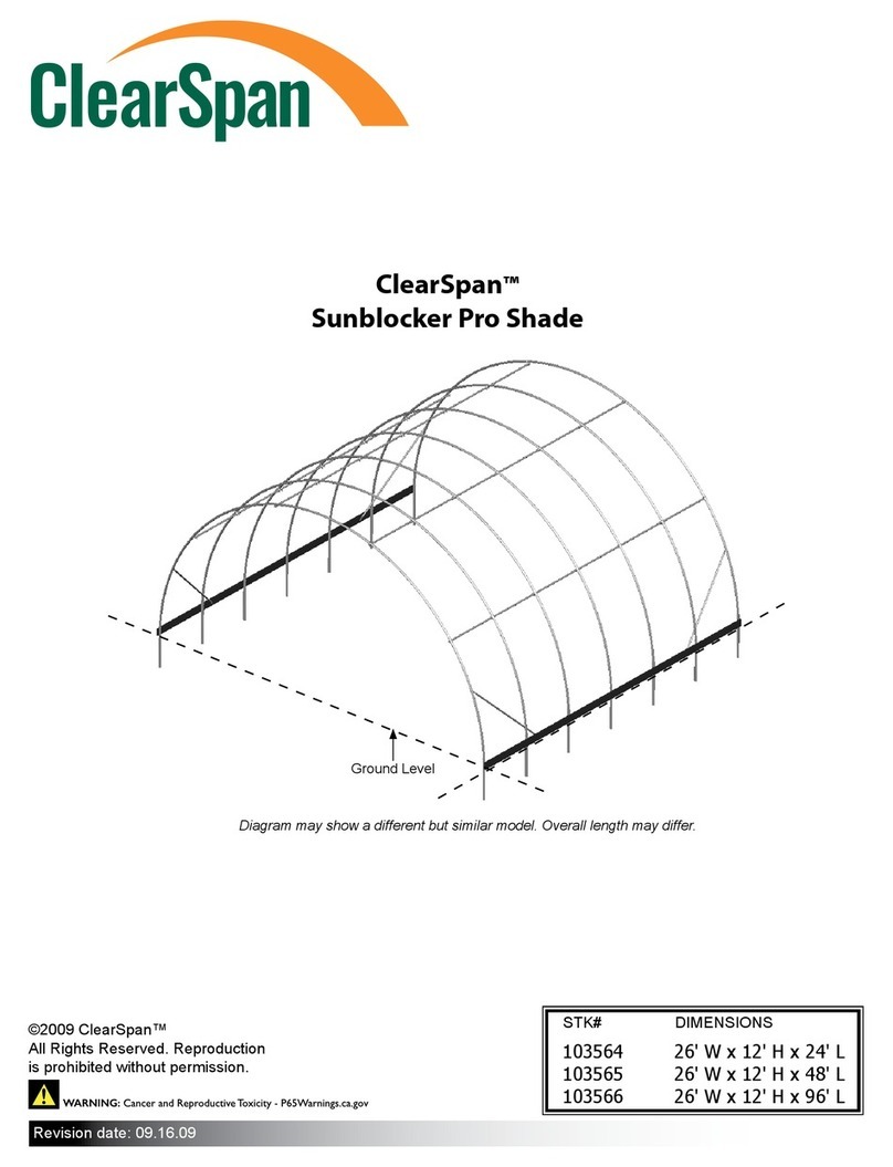
ClearSpan Sunblocker Pro Shade User manual

ClearSpan

ClearSpan Sunblocker Pro Shade User manual

ClearSpan 106186 User manual

ClearSpan

ClearSpan 106186 User manual

ClearSpan Pro Solar Star R035 User manual

ClearSpan

ClearSpan Pro Solar Star R035 User manual

ClearSpan Solar Star Series User manual

ClearSpan

ClearSpan Solar Star Series User manual

ClearSpan Pro Solar Star R035 User manual

ClearSpan

ClearSpan Pro Solar Star R035 User manual

ClearSpan 500 Series User manual

ClearSpan

ClearSpan 500 Series User manual

ClearSpan 500 Series User manual

ClearSpan

ClearSpan 500 Series User manual
Popular Lawn And Garden Equipment manuals by other brands

Z.I.P.P.ER MASCHINEN ZI-ELB70 user manual

Z.I.P.P.ER MASCHINEN

Z.I.P.P.ER MASCHINEN ZI-ELB70 user manual

sunjoe AJ801E user manual

sunjoe

sunjoe AJ801E user manual

FLORABEST 279218 Instructions for use

FLORABEST

FLORABEST 279218 Instructions for use

sunjoe SJ-BZ18W user manual

sunjoe

sunjoe SJ-BZ18W user manual

Oleo-Mac BC 22 TR Operator's instruction manual

Oleo-Mac

Oleo-Mac BC 22 TR Operator's instruction manual

FLORABEST 103480-14-01 Assembly and Safety Advice

FLORABEST

FLORABEST 103480-14-01 Assembly and Safety Advice

FLORABEST 295957 Instructions for use

FLORABEST

FLORABEST 295957 Instructions for use

N'oveen IKN4 Lampion instruction manual

N'oveen

N'oveen IKN4 Lampion instruction manual

In 2 Care Mosquito Station Quick installation guide

In 2 Care

In 2 Care Mosquito Station Quick installation guide

sunjoe NJPSC1 manual

sunjoe

sunjoe NJPSC1 manual

Deltafox DG-CGS 3615 Translation of the original instructions for use

Deltafox

Deltafox DG-CGS 3615 Translation of the original instructions for use

Z.I.P.P.ER MASCHINEN ZI-GPS182J user manual

Z.I.P.P.ER MASCHINEN

Z.I.P.P.ER MASCHINEN ZI-GPS182J user manual

FLORABEST TOZ96711 Assembly and Safety Advice

FLORABEST

FLORABEST TOZ96711 Assembly and Safety Advice

Euro Systems P70 Translation of original user instructions

Euro Systems

Euro Systems P70 Translation of original user instructions

Dura Trel ROSEBUD TRELLIS 11103 Assembly instructions

Dura Trel

Dura Trel ROSEBUD TRELLIS 11103 Assembly instructions

Gardeners 8596999 quick start guide

Gardeners

Gardeners 8596999 quick start guide

Gardeners 34-051 Product bulletin

Gardeners

Gardeners 34-051 Product bulletin

ATIKA LSH 2500 Original instructions

ATIKA

ATIKA LSH 2500 Original instructions

manuals.online logo
manuals.online logoBrands
  • About & Mission
  • Contact us
  • Privacy Policy
  • Terms and Conditions

Copyright 2025 Manuals.Online. All Rights Reserved.