2Revision date: 06.19.12
Table of Contents
READ THIS BEFORE YOU BEGIN
The main building and any accessory (end wall, door, etc.)
requires a specific installation sequence. All buildings
include an instruction guide; each accessory includes an
instruction guide.
Near the beginning of each instruction guide (building or
accessory), you will find information to lead you through
the installation and assembly steps. This information
identifies at what point during the assembly a particular
accessory is installed or attached to the main building
frame.
In all instances and regardless of the type and
number of accessories, the main building frame is
always constructed first.
Since we cannot anticipate changes made by the
customer/contractor, all instructions assume the use of
accessories purchased from us to be used on the building
the accessory was designed for. Each instruction guide
presents the basic steps to install the accessory.
When in doubt, consult the services of a qualified
contractor experienced with the assembly of similar
structures.
Assemble the main building frame now.
Important Information ..................................................3
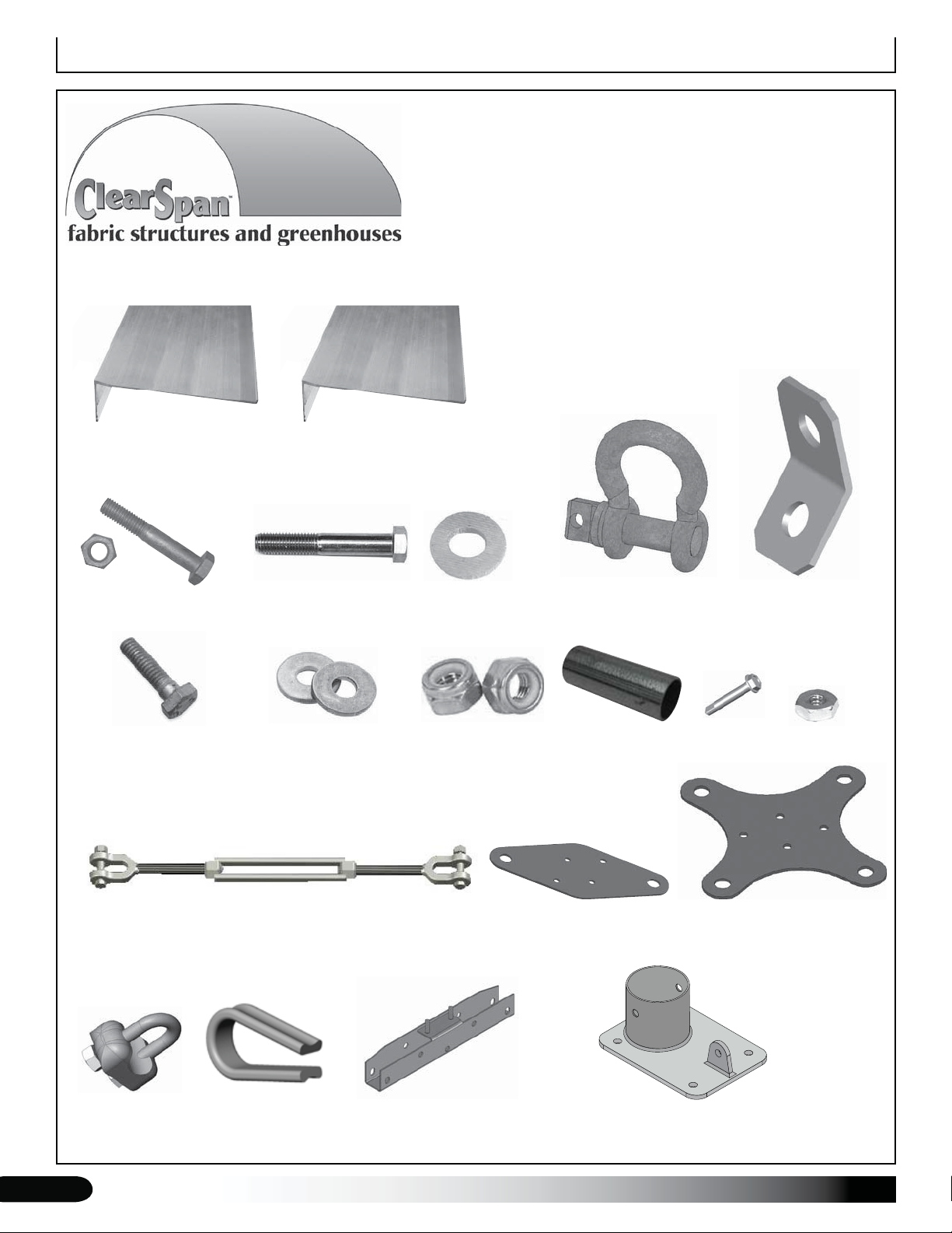
Parts Identification .......................................................6
Overview........................................................................7
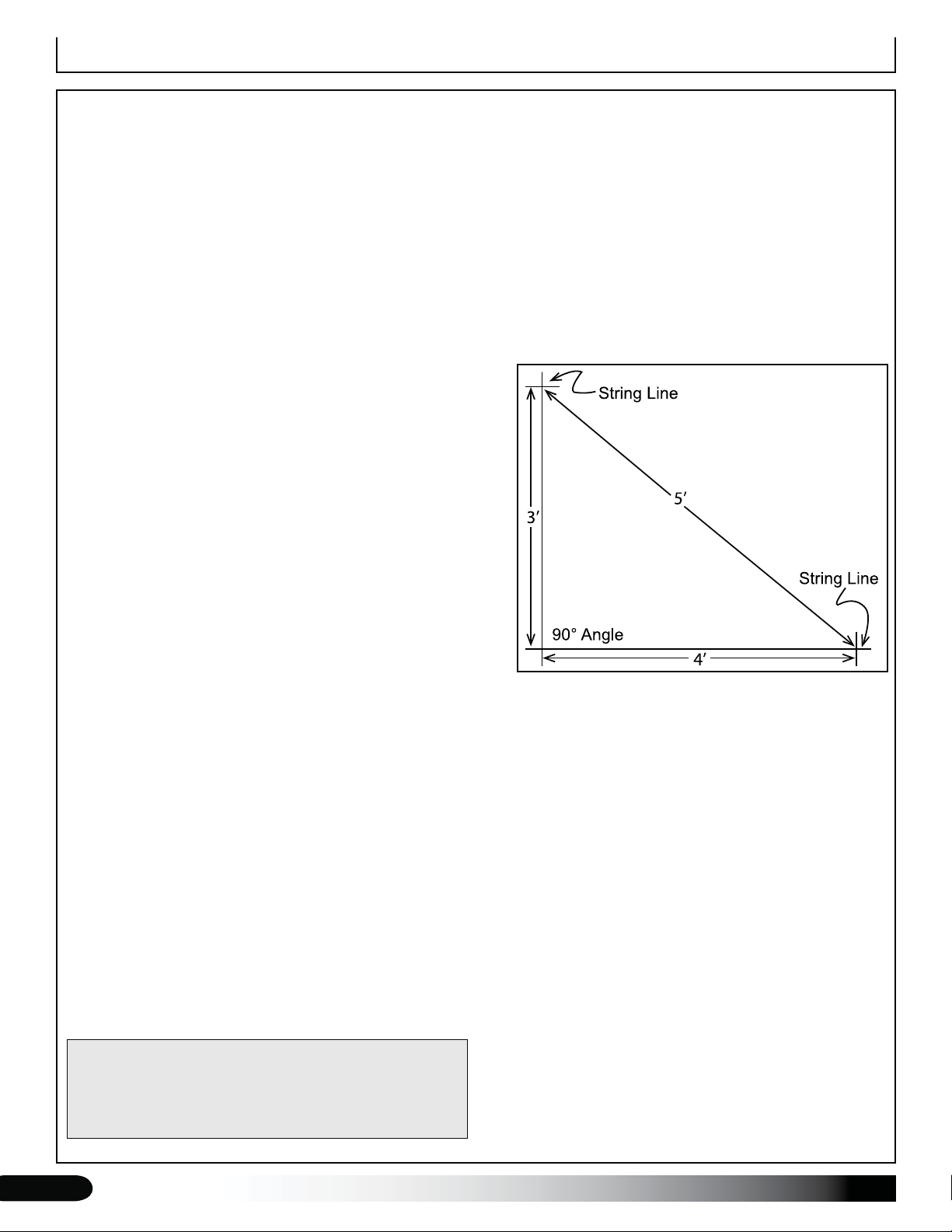
Prepare and Square the Building Site ........................8
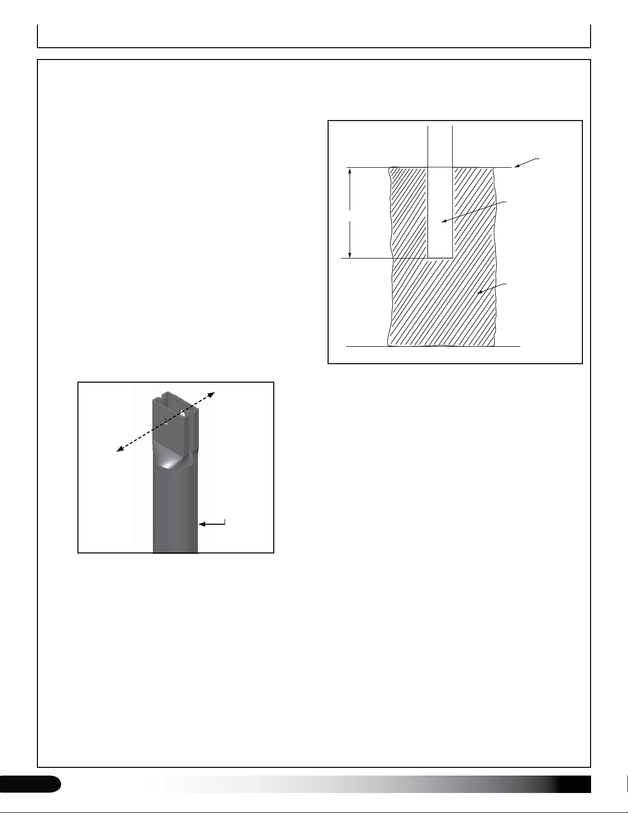
Set the Ground Posts (option) ....................................9
Mounting Feet (option).................................................11
Rafter Assembly ...........................................................12
Frame Assembly...........................................................13
Install Hat Channel .......................................................19
Recommended Baseboard Installation ......................20
Cable Installation..........................................................21
Diagonal Strut Installation...........................................23
Anchor the Assembled Frame.....................................24
Ridge Cap Installation..................................................25
End Cap Installation.....................................................26
Install Corrugated Panels ............................................27
Shelter Care and Maintenance ....................................35
Quick Start Guide .........................................................36
35' Wide Front Profile Grid with Ground Posts .........37
35' Wide Front Profile Grid with Mounting Feet.........38
35' Wide Front Profile with Ground Posts..................39
35' Wide Front Profile with Mounting Feet.................40
35' Wide Purlin Locations............................................41
Side Profile - 36' Length...............................................42
Side Profile - 48' Length...............................................43
Side Profile - 60' Length...............................................44
Side Profile - 72' Length...............................................45
Side Profile - 84' and 96' ..............................................46
Connections..................................................................47
Connection Details (1-4) ..............................................48
Connection Details (5-8) ..............................................49
Connection Details (9-12) ............................................50
Main Cover Details .......................................................51
Mounting Feet Layout ..................................................52
35' Wide Over-The-Top Measurements.......................53
Mounting Feet (108500) Layout Diagram
Buildings equipped with the 108500 mounting feet require
additional steps for the site preparation. Consult the
Mounting Feet Layout diagram in the Quick Start section
near the back of this guide for the required dimensions.
Do not prepare the site without first consulting the
diagram for the proper dimensions! In addition,
consult the MUST READ document for anchoring
details.
Buildings that include "P0" within the building
identification number (e.g., R035020P02FC01W) are
equipped with the 108500 mounting feet.
For buildings with ground posts, consult the Front Profile
with Ground Post diagram in the Quick Start section to
properly prepare the site.
Buildings that include "GP" within the building
identification number (e.g., R035020GP2FC01W) are
equipped with ground posts.
WIND AND SNOW LOAD
Many Clearspan™shelters and greenhouses can be
designed to meet wind and snow loading in your area.
Please consult with your account manager if needed for
additional information.
ANCHORING THE BUILDING
The anchoring methods shown in this manual for
buildings with mounting feet or buildings with ground
posts are temporary in nature. For the recommended
permanent anchoring methods, consult the MUST
READ documents that also shipped with your building.
The diagrams presented in that guide show anchoring
methods designed to meet typical loads and forces.
Consult that document and read its contents before you
begin construction.