ClearSpan 500 Series User manual

1
Revision date: 07.11.14
©2014 ClearSpan™
All Rights Reserved. Reproduction
is prohibited without permission.
Series 500 Tall High Tunnels–
30' Wide with Roll-Up Sides
Photo may show a building of a different length and style. Frame shown includes roll-up sides and customer-
supplied baseboards. Actual cover material may differ. Building shown is equipped with an optional roll-up end.
30' Wide Series 500 Tall High Tunnels:
All Standard Lengths.

2Revision date: 07.11.14
Important Information
READ THIS DOCUMENT BEFORE YOU
BEGIN TO ASSEMBLY
Thank you for purchasing a Series 500 high tunnel
structure. When properly assembled and maintained,
this product will provide years of reliable service. These
instructions include helpful hints and important information
needed to safely assemble and properly maintain the
structure. Please read these instructions before you
begin.
If you have any questions during the assembly, please
contact customer service for assistance.
SAFETY PRECAUTIONS
• Wear eye protection.
• Wear head protection.
• Wear gloves when handling metal parts.
• Use a portable GFCI (Ground Fault Circuit Interrupter)
when working with power tools and cords.
• Do not climb on the frame during or after construction.
• Do not occupy the structure during high winds,
tornadoes, or hurricanes.
• Provide adequate ventilation if the structure is
enclosed.
• Do not store hazardous materials in the structure.
• Provide proper ingress and egress to prevent
entrapment.
LOCATION
Choosing the proper location is an important step before
you begin.
The following suggestions and precautions will help
determine whether your selected location is the best
location.
• Never erect the structure under power lines.
• Identify whether underground cables and pipes are
present before preparing the site, setting ground
posts (if equipped), or anchoring the structure.
• Location should be away from structures that could
cause snow to drift on or around the building.
• Do not position the structure where large loads
such as snow and ice, large tree branches, or other
overhead obstacles could fall.
• Always check local building codes before you begin
and follow codes as instructed.
SITE
After choosing a location, proper preparation of the site is
essential. Follow the information below.
• A level site is required. The site must be level to
properly and safely erect and anchor the structure.
• Drainage: Water draining off the structure and from
areas surrounding the site should drain away from
the site to prevent damage to the site, structure, and
contents of the structure.
WARNING: The individuals assembling this structure
are responsible for designing and furnishing all
temporary bracing, shoring and support needed
during assembly. For safety reasons, those who are
not familiar with recognized construction methods
and techniques must seek the help of a qualified
contractor.
SETTING THE GROUND POSTS
The frame assembly of this building requires the
setting of all ground post in concrete. Review the
layout diagrams for additional details.
Enlist the services of a professional and competent
contractor to prepare the site and set the ground posts.
Failing to secure ground posts in concrete as required
may result in damage to the building, building contents,
and surrounding property.

3
Revision date: 07.11.14
Important Information
ASSEMBLY
Following the instructions as presented will help ensure
proper assembly. Failing to follow these steps may result
in an improperly assembled and anchored structure.
NOTE: Once the main frame is assembled, many of
the remaining procedures can occur simultaneously,
depending on available assistants and equipment.
Before you begin, review all technical documents to
better understand overall building design.
The steps outlining the basic frame assembly are as
follows:
1. Verify that all parts are included in the shipment.
Notify Customer Service for questions or concerns.
2. Read this guide and all additional documentation
included with the shipment before you begin.
3. Gather the tools, bracing, ladders, lifts, and
assistants needed to assemble the structure.
4. Check the weather before you install the roof cover
and any end panels (if equipped). Do not install
covers or panels on a windy or stormy day.
5. Re-evaluate the location and site based on the
information and precautions presented in the
documentation included with the shipment.
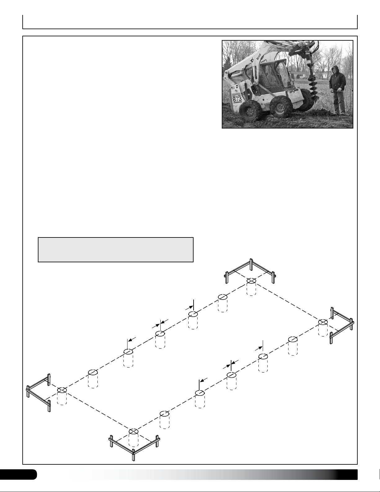
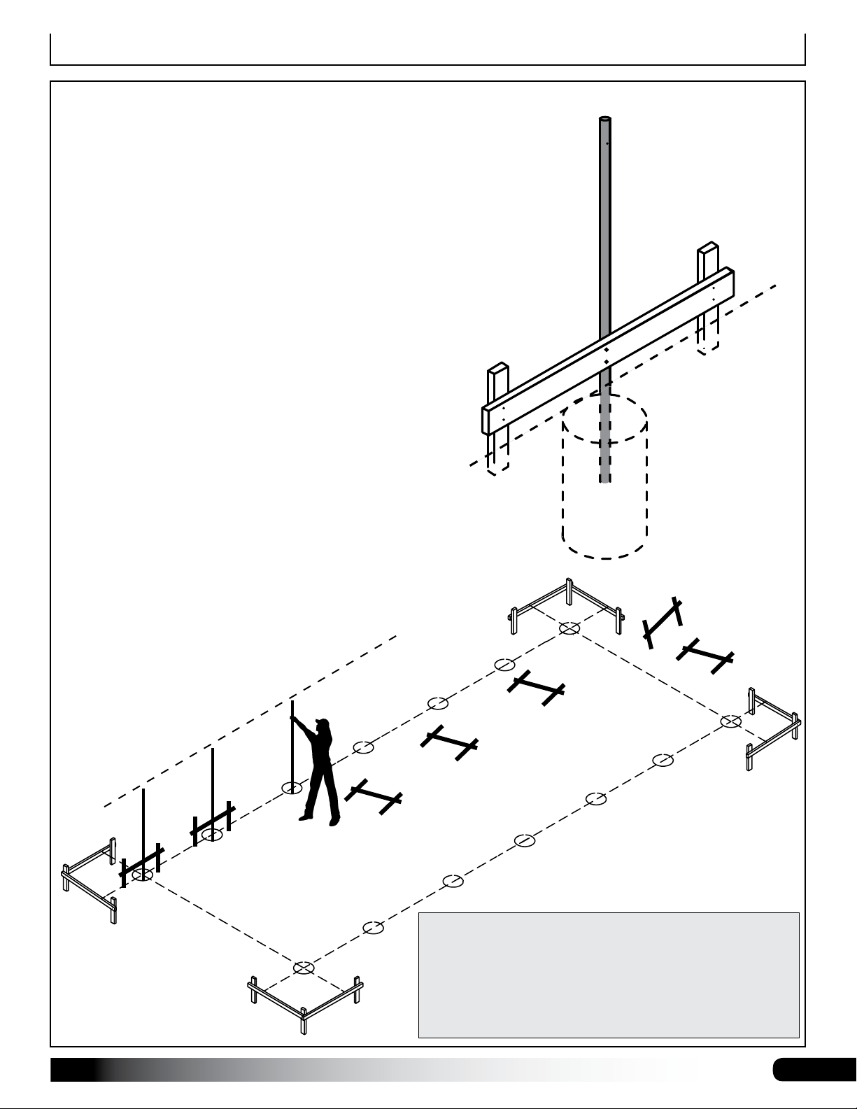
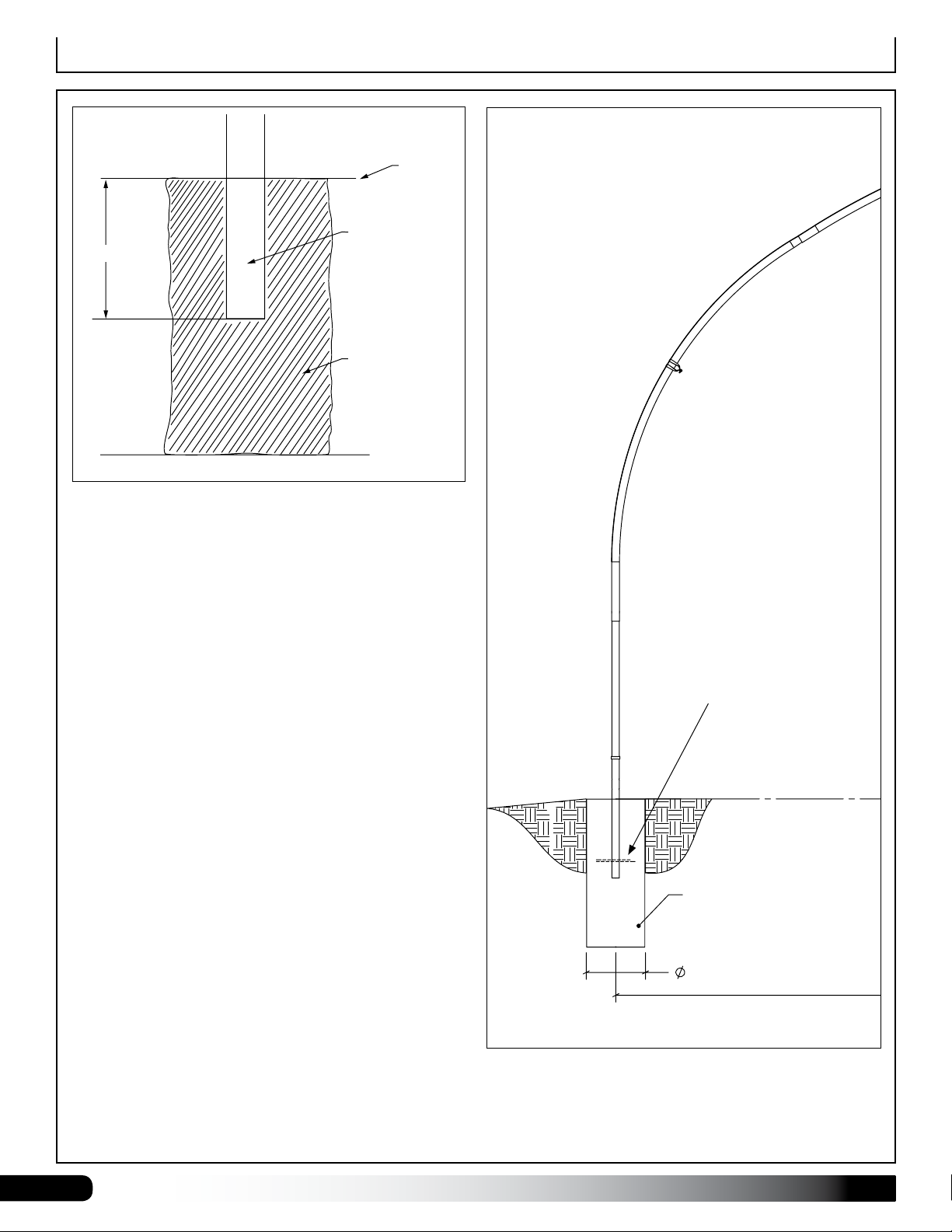
6. Prepare the site (if applicable) and set the ground
posts in concrete. If building includes end framing,
review those instructions and drawings for additional
end framing requirements.
7. Assemble rafter components and rafter support kit
components (if equipped). Optional support kits
require an additional purchase.
8. Assemble main building frame (rafters, cabling,
purlins, etc).
9. If used, attach baseboards and ribbon boards
(customer-supplied).
10. Attach 111613Z144 aluminum channel along the
sides for cover installation. Consult these instructions
and all drawings for additional details.
11. Install the optional ridge vent frame if equipped.
12. Install end wall frame, door frame, and end wall
cladding if equipped.
13. Attach 111613Z144 aluminum channel to the end
rafters.
14. Install main cover. This applies to film or 5.2 oz cover
material. If building is equipped with a ridge vent,
consult those instructions for additional steps for
cover installation.
15. Install roll-up (or drop-down) sides and anti-billow
ropes.
16. Complete and return all warranty information as
instructed if present.
REQUIRED TOOLS
The following list identifies the main tools needed to
assemble the shelter. Additional tools and supports may
be needed depending on the structure, location, and
application.
• Tape measure or measuring device and marker to
mark locations on the pipes and rafters.
• Variable speed drills and impact drivers. (Cordless
with extra batteries works best.)
• Metal-cutting saws or tools to cut pipe and
aluminum.
• Drill bit set
• Wrenches and impact socket set, hammer, and
gloves.
• Adjustable pliers and self-locking pliers.
• Ladders, work platforms, and other machinery for
lifting designed to work safely at the height of the
building.
• Safety equipment to protect head, eyes, hands and
feet.
UNPACK AND IDENTIFY PARTS
The following steps will ensure that you have all the
necessary parts before you begin to assemble the
shelter frame.
1. Unpack the contents of the shipment and place
where you can easily inventory the parts. Refer to
the Bill of Materials/Spec Sheets.
2. Verify that all parts listed on the Bill of Materials/
Spec Sheets are present. If anything is missing
or you have questions, consult the Pictorial Parts
Guide and all diagrams for clarification, or contact
Customer Service.
NOTE: Do not open plastic bags containing smaller
parts such as fasteners or washers at this time.
Simply verify quantity.

4Revision date: 07.11.14
Baseboards and Ribbon Boards
A customer-supplied baseboard is recommended for roll-
up sides that include the stabilizer bar. A baseboard runs
the length of the frame and provides a seal between the
finished grade and the stabilizer bar.
All baseboard and ribbon board material and
fasteners to secure these to frame are supplied by
the customer. See photo below.
Dimemsions
Recommended baseboard and ribbon board dimensions:
2" x 6" (minimum).
Recommendation: Use two (2) carriage bolts (exterior
finish) per rafter connection to secure the baseboards
and ribbon boards to the rafter legs/ground posts.
Actual frame shown in the examples above may differ.
These are presented for illustration purposes only.
Ground
Level
Inside of
Shelter
Outside of
Shelter
Secure baseboard (and ribbon
board) joints between rafters
as shown for best results.
RIBBON BOARD FOR ROLL-UP SIDES—OPTIONAL
In some instances, a ribbon board is installed along
the side of the frame. This is optional for buildings with
roll-up side panels. Customer supplies the materials and
fasteners for the ribbon board.
Stabilizer Bar
Baseboard
DIAGRAMS ARE NOT TO SCALE.
5/16" Carriage
Bolt (supplied
by customer)
2" x 6" Baseboard
(customer supplied)
Finished
Grade
2" x 6"
Ribbon Board if used.
(supplied by customer)
111613Z144
Channel
End View
5/16" Carriage
Bolt (supplied
by customer)
FAH005B Bolt FALB01B Nut
FALF01B Fender
Washer
Rafter Leg
or Ground
Post

5
Revision date: 07.11.14
Parts Identication
111613Z144 Aluminum
U-Channel
CC6212
Fabric Clip
103544
Mounting Plate
(Roll-Up or Drop-
Down Sides only)
103496
Gear Box
(Roll-Up or Drop-
Down Sides only)
102569 Roller
Bearing
(Roll-Up or Drop-
Down Sides only)
102546 Cross
Connector
QH1070
Pipe Strap
103856
Band Clamp
AS2167 Anchor
Shackle
AS1004 Clamp
104189 Turnbuckle
FA4482B
Tek Screw
FAG363B
3/8" x 3" Hex Bolt
FAME08B
3/8" Flat washer
FALB04B
3/8" Nut
100441 and 100443
Magnetic Nut Setter
The following graphics will help identify the basic parts of the frame. (Some
parts are not shown.)
AS1084
3/16" Cable Thimble

6Revision date: 07.11.14
ClearSpan™
Series 500 High Tunnel
Structures
Overview
Drawing may show a model of a different length. Refer to
Quick Start section located near the back of this guide for
on-center measurements and post layout.
Sample building shows roll-up sides and optional roll-up
door panel. (Wood for end frame is supplied by the customer.)
OVERVIEW
This section describes assembling your building frame.
See illustration below to identify main parts.
1. Prepare site and set the ground posts in concrete.
2. Locate the required parts for each assembly
procedure.
3. Assemble the rafters and main frame.
Ground Level
End Rafter
Interior Rafter
Ridge Purlin
Side Purlin
Cable
Ground
Post
On-center

7
Revision date: 07.11.14
Prepare and Square the Building Site
PREPARE THE BUILDING SITE
A level site is required to accurately and safely construct
the building. Consult the services of a qualified contractor
to properly grade and prepare the site.
Site should slope away from the building for proper water
drainage.
After the site is prepared, mark the location of the frame
corners to square the frame position. Taking these steps
before assembling the shelter saves time and ensures
that the structure is square and positioned as desired.
The following procedures are suggested methods.
Their use depends on the size of the shelter, shelter
application, the footings (if applicable), and the method
used to anchor the shelter.
When in doubt, consult the services of a qualified
contractor experienced with the construction of similar
structures.
Ground Posts
If the frame includes ground posts, set all ground posts
as described within this manual. Width of the shelter
is measured from the center of one ground post to the
center of the remaining ground post. Length is also
measured center-to-center. If your building includes
ground posts, continue with the Setting Ground Post
section.
SQUARE THE SITE: GENERAL STEPS
1. Identify a corner where a building rafter will be
positioned, drive in a stake, and string a line the exact
width of the building and stake in place. (Width of the
rafter is measured from center-to-center of the rafter
legs.)
2. After the first corner stake is in place, string a line the
width of the building (center-to-center) and drive the
second corner stake into the ground.
3. String a line at least as long as the building 90° from
the line between the first and second stakes.
NOTE: A transit can be used to ensure an accurate
90° angle, or the 3-4-5 rule can be used. Refer to
diagram. Using multiples of 3-4-5 such as 6-8-10 or
12-16-20 helps to maintain an accurate 90° angle.
4. After squaring the position of the building, measure
the length and drive the third corner stake.
5. Repeat the same step for the last corner stake.
NOTE: The distance measured diagonally between
corner stakes must be equal for the building to be
square.
SETTING THE GROUND POSTS
The frame assembly of this building requires the
setting of all ground post in concrete. Review the
layout diagrams for additional details.
Enlist the services of a professional and competent
contractor to prepare the site and set the ground posts.
Failing to secure ground posts in concrete as required
may result in damage to the building, building contents,
and surrounding property.

8Revision date: 07.11.14
Set Ground Posts
Drawing may show layout of a different length. Refer to
Quick Start section located in the back of these instructions
for on-center measurements and post layout for your frame.
MARK THE SITE AND DIG POST HOLES
These steps describe marking all post hole locations and digging
the holes. For some sites, it may not be possible to complete the
procedure in this manner. An alternative procedure such as working
from one end of the building toward the other may be necessary.
Determine the best procedure based on the site and other factors
and proceed as needed.
NOTE: Refer to the Quick Start Section located near the back
of these instructions for the Side Profile and related diagrams.
Complete these steps:
1. Stake the outline of the building using string line and batter boards. Set batter boards 3' back from the building
corners. Check to ensure that the building layout is square. Cover or panels (if equipped) will not install properly if
the building frame is not square once assembled.
2. Consult the diagrams in the Quick Start section to verify the frame length and width dimensions and to accurately
position the ground posts.
3. Guided by the string line, use a flag or stake to mark each ground post hole location.
4. Move the string line and dig a post hole a minimum of two feet (2') deep or to a depth that is below the geographic
frost line. Consult local building codes. A power auger works best. Minimum hole diameter is 12".
5. After digging all holes, reattach the string line to the batter boards and use it as a guide to set and align the
ground posts.
on-center
on-center
on-center
on-center

9
Revision date: 07.11.14
SET GROUND POSTS
Required parts and equipment:
• Ground Posts (112430) and 103856 Band Clamps
• Equipment to level and brace posts
NOTE: Concrete (customer-supplied) is required to secure
all ground post in the holes. Set all posts at the same height
for proper assembly. Position all rafter mounting holes to
point toward the outside/inside.
Consult the services of a qualified contractor to properly set
posts. Here are the basic steps:
1. Take one ground post, measure 24" from the end
opposite the single bolt hole, and mark the location on
the ground post. Repeat to mark all ground posts.
NOTE: The single rafter mounting bolt hole is to the top
of the ground post. Position the two pre-drilled holes in
the ground post toward the ground.
2. With assistance, brace all posts in place. See diagram
below. All posts to be plumb before adding concrete.
Use the baseboard mounting holes and customer-
supplied fasteners and stakes to hold posts in place.
3. Add concrete to anchor posts in holes. Fill hole so
concrete remains below the finished grade.
Stake Ground Posts for Concrete
Finished Grade
Set all posts at the same
height. Additional bracing may
be needed to keep the post
plumb while concrete sets.
Customer-supplied braces
and fasteners.
SETTING THE GROUND POSTS
The ground posts include pre-drilled rafter mounting bolt
holes and holes to attach the baseboards. Position holes
so they point to the outside/inside of the frame.
Do not position holes to point toward the ends of the frame.
Set Ground Posts
Set top of posts at the same
height. Posts set in concrete
24" below nished grade.

10 Revision date: 07.11.14
Set the Ground Posts
30'-0"
CONCRETE PIER
GROUND LEVEL
CONCRETE PIER
12"
12"
Ground Post
Concrete
Ground Level
2’ Deep
In areas where frost is common, dig each post hole so
it falls below the frost line. Minimum hole depth for all
areas regardless of frost is 24". Minimum hole diameter
is 12". Set all ground posts 24" below finished grade.
Consult local building codes and qualified contractors for
additional details when digging the post holes and setting
the ground posts.
Follow established codes and construction practices.
Optional: Before setting the
posts, drill a hole through the
bottom of each ground post
2"-3" from the end and insert
a 6"-8" length of rebar through
it. This will help stabilize and
anchor the ground posts once
the concrete sets.

11
Revision date: 07.11.14
Rafter Assembly
RAFTER ASSEMBLY
After setting the ground posts, continue with the rafter assembly. Do not set assembled rafters into position on the
ground posts until concrete has set. Check with contractor for set times.
NOTE: All rafter assemblies consist of three main rafter sections. Consult the rafter diagrams in the Quick Start section
of these instructions before and during the rafter assembly process for details. Assistance is required to assemble the
rafters and frame. Assemble all main sections of rafters as described below and set aside.
STEP 1: Select
the rafter pipes
to assemble one
rafter.
STEP 3: Secure
each rafter joint
using two (2) Tek
screws.
STEP 2: Slide
the separate pipe
pieces together.
STEP 4: Wrap
each splice and
Tek screws with
duct tape to pro-
tect the cover.
PG500TC23G16S02
PG500TC2316S301 PG500TC2316S302
PG500TC23G16S02
30' Wide Rafter

12 Revision date: 07.11.14
Rafter Assembly–Optional Support Kit
Complete these basic steps:
1. Slide the 103856 band clamps into position on the assembled rafter.
2. Assemble the 1.90" diameter cross beam.
3. Slide QH1404 band clamps onto the cross beam.
4. Secure each splice of the cross beam using two (2) Tek screws.
5. Verify dimensions and position of support kit components and install web components.
6. Return to each band clamp and secure each clamp to the rafter using a Tek screw. Install Tek screw in a position
that will not contact the cover when it is installed.
(190S164G14)
CROSS BEAM
CROSS BEAM
ST05050D13G17S1
(190P166G14)
BAND CLAMP
(103856)
(QH1404)
BAND CLAMP
(103856)
BAND CLAMP
ST08475D13G17S1)
(QH1404)
BAND CLAMP
BAND CLAMP (QH1404)
(
)
(103856)
BAND CLAMP
BAND CLAMP
WEB
(103856)
)WEB
(
ST05050D13G17S1)
WEB
(ST08475D13G17S1
WEB
(
Support Kit Components for a
30' Wide Rafter
RAFTER ASSEMBLY—Optional Support Kits
If the optional support kits were purchased, continue with the assembly steps that follow. Consult the diagrams
supplied with the rafter support kits for additional details. See also the diagram in the Quick Start section of this guide.
If the support kits were not purchased, continue with the frame assembly.
ATTENTION: Support kit components are typically not installed for the end rafters when end wall framing is present.

13
Revision date: 07.11.14
Frame Assembly
FRAME ASSEMBLY
Use the diagrams and information that follows to assemble the main frame.
ATTENTION: Rafters are heavy. Always lift rafter from two separate points to prevent damage and injury.
Examine the site to determine the best way to move the rafters into position and to set them onto the ends of each set
of ground posts. Do not set rafters into position until the ground post concrete has set.
Optional, but recommended—especially for long buildings: Build a Rafter-Spacing Jig (Customer supplies materials.)
A spacing jig saves time and helps to evenly space the rafters. Jig sets the on-center spacing of rafters. Examine the
photo below and use it to build a jig to space rafters during purlin installation. Use 2" x 4" lumber and wood fasteners.
Customer-supplied
rafter-spacing jig.
Finished Grade
(2) 103856
Clamps
(2) 103856
Clamps
(2) 103856
Clamps
(2) 103856
Clamps
Rope or
Cable
Slide two 103856 band clamps over each
of the first two ground posts at each end
of the frame.
ATTENTION: Anchor the first rafter in place using bracing or
rope/cable. Do not allow the first rafter to stand without bracing
until additional rafters are set and purlins are installed.
Connect rafter to ground post using:
FAG363B (3/8") bolts, FAME08B washers,
& FALB04B nuts.

14 Revision date: 07.11.14
Frame Assembly
FRAME ASSEMBLY (continued)
Use this diagram to properly position the purlins during the frame assembly. Side purlins will run just above the cross
beam of the rafter support kit components if equipped.
Center the ridge purlin on top of the rafters. Secure
using the QH1070 and FA4482 Tek screws. Install
one Tek screw through the side of the strap and
into the purlin pipe.
Finished Grade
Approximately
11'
Secure side purlins at 11'
above the finished grade.
Secure purlin using QH1070
pipe straps at each end
rafter. Use 102546 cross
connectors at each mid
rafter position.

15
Revision date: 07.11.14
Purlin Pipe
Purlin Pipe
Frame Assembly
After setting the first end rafter and bracing it in place, set the second
rafter and add the purlins and purlin clamps. Consult the techincal
diagrams for connection details. Diagrams show the optional rafter
support package. Additional purchase required.
After the first few rafters are set and connected
by purlins, remove the end rafter bracing and
continue with the frame assembly.
FRAME ASSEMBLY (continued)
IMPORTANT!
Secure each QH1070 pipe strap to the purlin pipe using one Tek screw. Secure
all 102546 cross connectors to the rafter and to the purlin pipe using Tek screws.
Secure all purlin pipe splices using two Tek screws. See photos on next page.

16 Revision date: 07.11.14
Frame Assembly
FRAME ASSEMBLY (continued)
QH1070
Pipe Strap
Purlin
End Rafter
FA4482B Tek
Screw
FA4482B Tek
Screw
Purlin
FA4482B Tek
Screw
Secure each QH1070 pipe strap to the purlin pipe
using one Tek screw.
Photo shows the installation of the side purlin and pipe
strap at the end rafter. See Connection Details in Quick
Start section for additional information. Ridge purlin is
installed on top of the rafters unless noted.
Secure all 102546 cross connectors to the rafter and to
the purlin pipe using Tek screws.
Secure each purlin pipe splice using two Tek screws.
FA4482B Tek
Screws
102546 Cross
Connector
Purlin
Mid Rafter
(Between End Rafters)
Purlin Pipe
#2
End of Purlin
Pipe #2
inside #1
Purlin Pipe
#1
Purlin Pipe
Splice

17
Revision date: 07.11.14
Frame Assembly
FRAME ASSEMBLY (continued)
Customer-supplied
rafter-spacing jig.

18 Revision date: 07.11.14
Frame Assembly
FRAME ASSEMBLY (continued)
Full Frame without Optional
Rafter Support Components
Full Frame with Optional
Rafter Support Components
NOTE: Some frames may also
include support components on the
end rafters. This example does not.
ATTENTION: Example shows a
48' frame length. Actual frame may
differ.
CABLE ASSEMBLY AND INSTALLATION
IS SHOWN IN A LATER PROCEDURE.

19
Revision date: 07.11.14
Baseboard Installation—Recommended
BASEBOARD INSTALLATION—RECOMMENDED
Gather the parts:
• 2" x 6" treated lumber (supplied by customer).
• 5/16" carriage bolts and nuts supplied by customer.
Length depends on the thickness of the baseboard.
When properly installed, baseboard runs the length of
the frame at ground level. The baseboard is supplied by
the customer. The following procedure describes one
way to install the baseboards. The size and type of the
baseboard you choose may require the use of alternative
steps.
On the outside of the frame, attach the first baseboard
to the rafter using two (2) 5/16" carriage bolts and nuts.
Countersink bolt heads if carriage bolts are not used.
Continue adding baseboards to complete the first run.
Splices are made between posts as shown in the drawing
below. Use a short section of baseboard to secure
separate baseboards at a splice. See diagram below.
Repeat steps to install the second run of baseboard on
the remaining side of the frame.
NOTE: The boards should be at ground level or slightly
into grade to create a good seal between the board and
finished grade. After installing the baseboards, continue
with these instructions.
Inside of
Shelter
Finished Grade
Ground Posts and Baseboard
Baseboard
The above diagrams present examples only. Actual installation
depends on customer-supplied materials and other factors.
Finished
Grade
5/16" Nuts
Splice
5/16" Carriage
Bolts
Outside of
Shelter

20 Revision date: 07.11.14
Diagonal Cable Installation
Using the diagrams and photos, install the diagonal cables at each end bay of the frame.
Attach the lower end of each cable assembly to the band
clamp approximately 4"- 6" above the top edge of the
baseboard. Secure each band clamp to the rafter using
a Tek screw before tightening the cable turnbuckles. See
photos on the next page.
Live cable end.
Dead cable
end.
Other manuals for 500 Series
1
Table of contents
Other ClearSpan Lawn And Garden Equipment manuals

ClearSpan
ClearSpan Sunblocker Pro Shade User manual

ClearSpan
ClearSpan Pro Solar Star R035 User manual

ClearSpan
ClearSpan 106186 User manual

ClearSpan
ClearSpan PREMIUM COMBO PB02804R4N User manual

ClearSpan
ClearSpan Pro Solar Star R035 User manual

ClearSpan
ClearSpan Solar Star Series User manual

ClearSpan
ClearSpan 500 Series User manual