ClearWater Lights Spyder RT User manual
The Clearwater Company
2546 Mercantile Dr. Ste B
Rancho Cordova, CA 95742
Ph:916.852.7029 Fx:916.852.9410
www.clearwaterlights.com
Installation
Manual
Spyder
RT and RS
Glenda LED Light Kit
(Dimmable)

Please be sure to read our instructions
thoroughly before attempting installation.
First, park the motorcycle on hard pavement or concrete to
insure the bike will be stable during the installation. Famil-
iarize your self with Body panel removal prior to installation.
Note: Clearwater lights include a very high quality means of
connecting to the motorcycle’s electrical system. “Posi”
devices made by Posi-Products are used to securely and
safely make electrical connections on the bike. You can view
instructions on the proper installation of the Posi-Products
at http://www.posi-lock.com. They simply screw together and
mate the wires. We suggest keeping your lights on all the
time, we do not furnish an “on-off” switch. It is important to
be sure that the wire you use will turn off when the bike is
turned off. Otherwise, you will end up with a dead battery.
Prior to Starting, Verify all the Parts are included per the
Parts list supplied with your kit to be sure all parts are handy.
If not , Contact Clearwater Lights at (916) 852-7029.
Fig 1

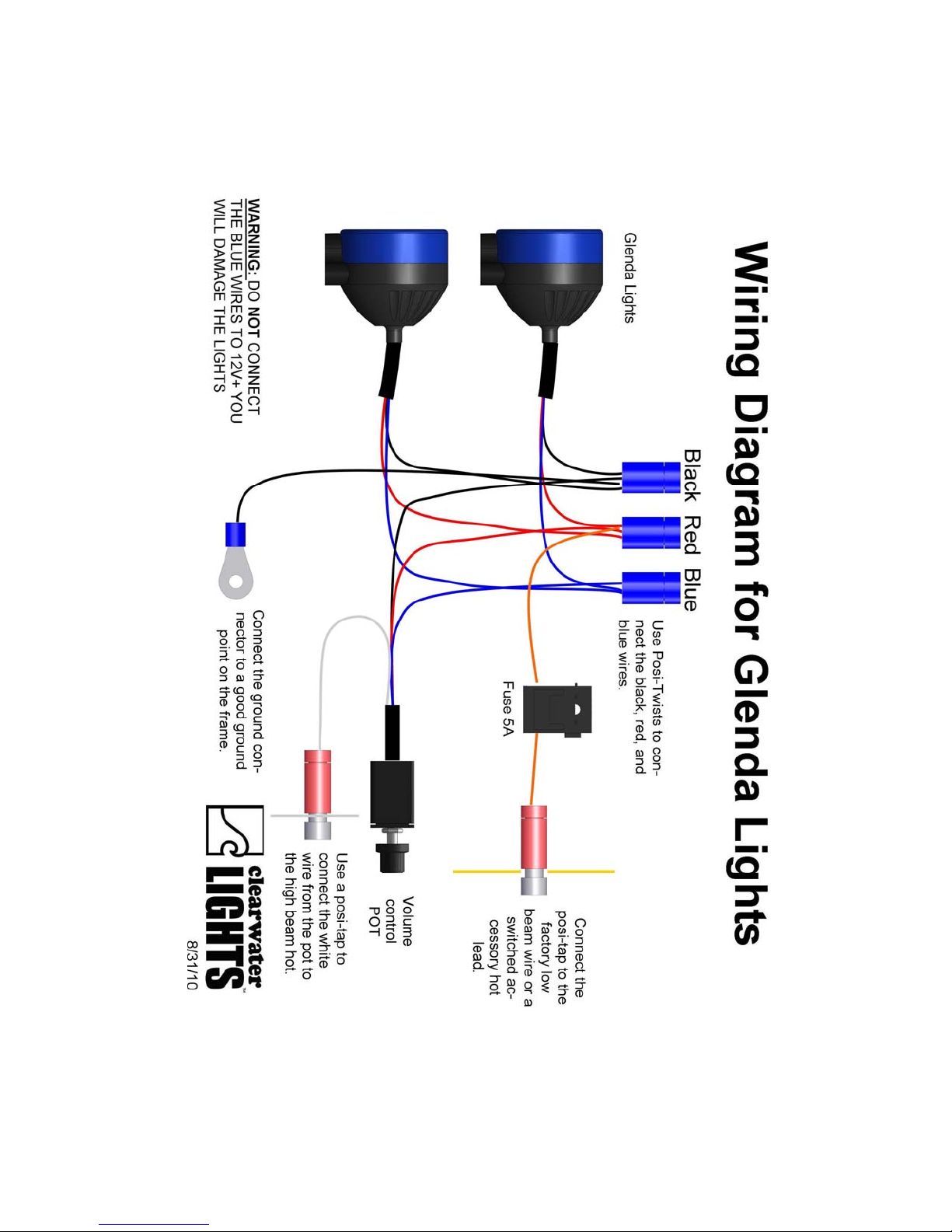
Electrical:
• Main power needs to be connected to a SWITCHED
HOT. This means one that turns off with the key. An
Auxiliary hot is an alternative. Using the supplied Posi-
twist connectors, connect the wires according to the ac-
companying color wire diagram. Attach ground lug to
ground on frame tab or other suitable location.
• Use posi-twist to connect red from fuse holder to red
wires from lights and pot (4 wires)
• Connect ground/black wire to black wires from lights
and pot (4 wires)
• Connect the Blue wire from pot to the blue wires from
the lights (3 wires)
• Connect the white wire from the pot to the high beam
headlight hot wire with a positap if you would like to
use the high beam feature.
• DO NOT CONNECT BLUE WIRES TO 12 volts +.
You will damage the lights.
Wire routing:
• Be sure to route wires so that the cannot become tangled
or caught in either a suspension part or steering part.
Check movement of both steering and suspension before
riding the bike.
• It is sometimes helpful to follow existing wire routing.
High Beam Feature
• Our lights come with a feature that makes them flash to
full power when you activate the high beam headlight. If
you would like to use this feature (recommended), fol-
low these instructions.
• Locate the HIGH BEAM headlight wire. This will be on
ONLY when the high beam is illuminated. This will
trigger our pot to control the brightness of the lights.
Connect the WHITE wire from the pot to this HIGH
BEAM circuit wire. See wiring diagram on following
page for details.

Removing body panels (You will be working on the left side of
the bike only, leave plenty of room)
Pop off the left lower access panel with the Can Am logo. It is held
on with 4 rubber washers
Fig 2
Fig 3
RT Installation Instructions start here.
This manual suits for next models
2


