Cleco 220 Series User manual

For additional product information visit our website at http://www.apextoolgroup.com
Parts Manual
823002
05/10/2011
220 Series
Precision Die Grinders
220 G X - 600 C XX - X
Tool Series
220
Tool Style
G = Grinder
Throttle Terminations
-- = Push-Pull
L= Lever
Speed Options (RPM)
600 = 60,000
Wheel Type
C = Collet
Termination Code
1 = 3/32" Collet
2 = 1/8" Collet
3M = 3mm Collet
Kit
K = Kit

2
Safety Recommendations
For your safety and the safety of others, read and understand
the safety recommendations before operating any grinder.
Always wear protective equipment and clothing.
Caution:Facesh-
ields do not pro-
vide unlimited
protectionagainst
flying particles
and are not to be
consideredassufficienteyeprotection.ANSIZ87.1statesthat
additional separate eyewear shall be used. For additional
information on eye protection, refer to Federal OSHA Regula-
tions,29CFR,Section1910.133,EyeandFaceProtection,and
ANSI Z87.1, Occupational and Educational Eye and Face
Protection. This standard is available from the American Na-
tionalStandardsInstitute,Inc.,11West42ndStreet,NewYork,
NY 10036.
Hearing protec-
tion is recom-
mended in high
noise areas
(above 85 dBA).
Closeproximityof
additional tools, reflective surfaces, process noises, and reso-
nant structures can substantially contribute to the sound level
experienced by the operator. Proper hearing conservation
measures,includingannualaudiogramsandtrainingintheuse
and fit of hearing protection devices may be necessary. For
additional information on hearing protection, refer to Federal
OSHA Regulations, 29 CFR, Section 1910.95, Occupational
Noise Exposure, and American National Standards Institute,
ANSI S12.6, Hearing Protectors.
• Gloves and other protective clothing should be worn as
required, unless they create a greater hazard.
• Do not wear loose fitting clothing, or clothing that may
restrict movement, become entangled or in any way
interfere with the safe operation of the grinder.
Grinding or other
use of this tool
mayproducehaz-
ardous fumes
and/or dust. To
avoid adverse
health effects, utilize adequate ventilation and/or a respirator.
Respirators should be selected, fitted, used and maintained in
accordance with Occupational Safety and Health Administra-
tion and other applicable regulations. Read the material safety
data sheet on any materials involved in the grinding process.
Cleco grinders are designed to operate on 90 psig (6.2 bar)
max. air pressure. If the tool is properly sized and applied,
higher air pressure is unnecessary. Excessive air pressure
increases the loads and stresses on the tool parts and may
result in breakage. Installation of a filter-regulator-lubricator in
the air supply line is highly recommended.
OVER
CAUTION!
Personal hearing protection is
recommended when operating
or working near this tool.
WARNING!
Impact resistant eye protection
must be worn while operating
or working near this tool.
Read Operating Instructions carefully. Follow
the Safety Recommendations for your safety
and the safety of others.
Hearing protection is recommended in high noise
areas (above 85 dBA). Close proximity of other
tools, reflective surfaces, process noises, and
resonant structures can substantially contribute
to the sound level experienced by the user.
WARNING
!
Repetitive work motions and/or vibration
can cause injury to hands and arms.
Use minimum hand grip force consistent with
proper control and safe operation.
Keep body and hands warm and dry.
Avoid anything that inhibits blood circulation.
Avoid continuous vibration exposure.
Keep wrists straight.
Avoid repeated bending of wrists and hands.
Do not remove this tag until
the operator of this tool has
read these safety precautions.
202101
WARNING TAG
PHOTO TACHOMETER
RPM
WARNING!
Impact resistant eye protection
must be worn while operating
or working near this tool.
CAUTION!
Personal hearing protection is
recommended when operating
or working near this tool.
WARNING
!
Wear respirator where
necessary.
Before the tool is connected to air supply, check throttle for
proper operation, i.e., throttle moves freely and returns to
closedposition.Beingcarefulnottoendangeradjacentperson-
nel, clear air hose of accumulated dust and moisture. Use
protective barriers where necessary —hot sparks can burn.
Barriers also help reduce noise levels. Before removing tool
fromserviceorchangingaccessories,makesureairlineisshut
off and drained of air. This will prevent tool from operating if
throttle is accidently engaged. Do not use tool to drain residual
airfromairline,insteaduseofaself-relievingvalvelocatednear
tool is highly recommended.
The speed rating and warning information on the tool
should be maintained or replaced for legibility in the event
of damage. Beforeinstalling any accessory (mounted wheels,
carbide burrs, etc.), after all tool repairs, and whenever a
grinder is issued for use, check the free speed of the tool with
atachometertomakesureactualfreespeedat90psigdoesnot
exceed rated free speed stamped on tool. Grinders in use on
the job must be checked at least once every 20 hours of
operation, or once a week, whichever is most frequent.
INSPECT THE MOUNTED WHEEL OR CARBIDE BURR
Fragments from a mounted wheel
orcarbideburrthatbreaksorcomes
apartwhilerotatingcancauseseri-
ous injury or even death. Inspect mounted wheel or acces-
sory.Checkthemaximum safe RPM marked on the accessory
or package. Never use an accessory rated at or below actual
tool speed. Cracked, dropped, faulty, or bent accessories
are dangerous. Suspect accessories should not be used and
should be disposed of. Look for cracks, chips, water stains, or
signs of abuse or improper storage. Causes of accessory
failures have been traced to such factors as:
•Dropping, bumping, or abuse (careless handling of the
grinder)
•Improper mounting
•Imbalance
•Improper shipment or storage, or age
•Mismatched speed ratings
•Exposureto water,solvents,highhumidity, freezing,and
extreme temperatures
Accessories known to have been subjected to any of the
conditions above can burst violently and should be de-
stroyedratherthanrisktheirusebysomeonewhomaynot
notice that they are damaged.
WARNING
!

3
Extension Neutral Flexion Radial Deviation Neutral Ulnar Deviation
Avoid Avoid Avoid
OK Avoid OK
ACCESSORY MOUNTING
The collet should be checked to assure it is in good operating
condition and is secure to the tool. Accessories should be
inserted to full depth of the collet. Avoid excessive overhang
that can result in vibration, or a bent spindle if excessive
downforce is used. Possible loss orejection of accessory
can result.
220G grinders are intended for use with
small carbide burrs and mounted wheels
only. Do not use these tools for Type 1 wheel grinding. If your
application calls for a Type 1 wheel, consult your Cleco repre-
sentative for a wheel grinder equipped with the proper wheel
guard.
This is a high speed low torque tool! The
speed(RPM)accomplishesthework.When
using do not force tool, simply hold and guide. Small accesso-
riesused with this toolcan be easily bentif forced and ifso can
be ejected from the collet.
BEGINNING GRINDING OPERATION
Before using or after mounting an accessory, tool must be run
forone minute in aprotectedenclosuretocheck the integrity of
theaccessory.Duringthistimeoranyothertime,nooneshould
stand in front or in line of the accessory. When starting work
with a cold wheel, apply it gradually to the workpiece until it
becomes warm. Do not continue to use a grinder if:
•The speed rating of the accessory is less than the speed
of the grinder
•It starts to vibrate
•Yousensechangesintool speed or an unusual increase
in noise that would indicate tool is running at excessive
speed
•You notice excessive end play in spindle
•You hear any unusual sound from grinder
RETURN THE TOOL TO THE TOOL CRIB FOR SERVICE
IMMEDIATELY!
Some individuals
may be suscep-
tible to disorders
of the hands and
arms when per-
forming tasks
consisting of
highly repetitive
motions and/or
exposure to ex-
tended vibration. Cumulative trauma disorders such as carpal
tunnel syndrome and tendonitis may be caused or aggravated
by repetitious, forceful exertions of the hands and arms. Vibra-
tionmaycontribute to a condition called Raynaud'sSyndrome.
These disorders develop gradually over periods of weeks,
months, and years. It is presently unknown to what extent
exposure to vibrations or repetitive motions may contribute to
the disorders. Hereditary factors, vasculatory or circulatory
problems, exposure to cold and dampness, diet, smoking and
work practices are thought to contribute to the conditions. Tool
operators should be aware of the following warning signs and
symptoms so that a problem can be addressed before it
becomes a debilitating injury. Any user suffering prolonged
symptoms of tingling, numbness, blanching of fingers, clumsi-
nessorweakenedgrip,nocturnalpaininthehand,oranyother
disorder of the shoulders, arms, wrists, or fingers is advised to
consult a physician. If it is determined that the symptoms are
jobrelatedoraggravated bymovementsandposturesdictated
by the job design, it may be necessary for the employer to take
steps to prevent further occurrences. These steps might in-
clude, but are not limited to, repositioning the workpiece or
redesigningtheworkstation,reassigningworkerstootherjobs,
rotating jobs, changing work pace, and/or changing the type of
toolusedsoastominimizestressontheoperator.Sometasks
may require more than one type of tool to obtain the optimum
operator/tool/task relationship.
The proper selection of the correct type of grinder is an
important ergonomic consideration. Each application should
be carefully considered and the tool chosen that will minimize
the stresses on the operator that can lead to the onset of
cumulative trauma disorders. Some tasks require more than
one type of tool to obtain the optimum operator/tool/task
relationship. Cleco has a complete selection of tools including
vertical, straight, angle, and extended grinders that make
possiblethe correctergonomicmatch oftheoperator, tool,and
task.
The following suggestions will help reduce or moderate the
effects of repetitive work motions and/or extended vibration
exposure:
•Use a minimum hand grip force consistent with proper
control and safe operation
•Keep body and hands warm and dry (cold weather is
reported to be a major factor contributing to Raynaud's
Syndrome)
•Avoid anything that inhibits blood circulation
—Smoking Tobacco (another contributing factor)
—Cold Temperatures
—Certain Drugs
•Tasks should be performed in such a manner that the
wrists are maintained in a neutral position, which is not
flexed, hyperextended, or turned side to side
•Stressful postures should be avoided —select a tool
appropriate for the job and work location
Safety Recommendations
3/4" MAX.
OVER HANG
WARNING
!
WARNING
!
Repetitive work motions and/or vibration
may cause injury to hands and arms.
Use minimum hand grip force consistent
with proper control and safe operation.
Keep body and hands warm and dry.
Avoid anything that inhibits blood circulation.
Avoid continuous vibration exposure.
Keep wrists straight.
WARNING
!
Avoid repeated bending of wrists and hands.

4
•Avoid highly repetitive movements of hands and wrists,
and continuous vibration exposure (after each period of
operation, exercise to increase blood circulation)
•Usequalityaccessories(theprimarysourceofvibration
when using a grinder is an accessory that is out of
balance, out of round, untrue, or possibly any combina-
tion of all three; avoid excessive overhang of accessory
in collet)
•Use carbide burrs that are sharp, as dull burrs require
more force and effort to remove material
•Keep tool well maintained and replace worn parts (a
preventivemaintananceprogramwithscheduledinspec-
tions is highly recommended)
Work gloves with vibration reducing liners and wrist supports
are available from some manufacturers of industrial work
gloves. Tool wraps and grips are also available from a number
of different manufacturers. These gloves, wraps, and wrist
supports are designed to reduce and moderate the effects of
extendedvibration exposureandrepetitivewrist trauma.Since
theyvary widely indesign,material,thickness, vibration reduc-
tion, and wrist support qualities, it is recommended that the
glove,toolwrap,orwristsupport manufacturerbeconsultedfor
itemsdesignedforyourspecificapplication.WARNING!Proper
fit of gloves is important. Improperly fitted gloves may
restrict blood flow to the fingers and can substantially
reduce grip strength.
USE QUALITY ACCESSORIES
The primary source of vibration when using a die grinder is an
accessory that is out of balance, out of round, untrue, or
possibly any combination of all three.
The use of accessories which are well balanced, round, and
true is highly recommended as they have been found to
significantly reduce vibration. Some accessories lose their
balance, roundness, and trueness as they wear from use.
Becauseof theabusivenature ofthevibrationcaused byoutof
balance, out of round, and untrue condition of some mounted
wheels and carbide burrs, it is felt that these accessories are
more susceptible to failure. Excessive vibration may signal
eminent wheel failure. Out of balance accessories are danger-
ous. Flat spotting of a mounted wheel, caused by grinding the
wheel to a stop after the power has been shut off can result in
changes to the balance and shape of the wheel. Be sure the
mounted wheel has stopped before setting the tool down. Set
the tool in a tool rest or tool holder when not in use.
USE A PREVENTIVE MAINTENANCE PROGRAM
Tool abuse or poor maintenance procedures can amplify and
contribute to the vibration produced by a mounted wheel or
carbide burr. A preventive maintenance program featuring
scheduled periodic inspections and proper maintenance is the
best way to assure safety in your portable grinding operations.
A well managed program can, for example, detect such things
as speed variations due to wear, flanges or spindles that have
been damaged from abuse, or bad bearings damaged by
foreign matter or lack of lubrication. Problems such as these
can affect the wheel trueness when the grinder is running and
contribute to the vibration. Rotor blades that are worn or
chippedcanlockupthemotoranddamagemotorcomponents.
Rotor blades should be replaced anytime the tool is disas-
sembled for service.
Proper repair procedures and the use of original Cleco service
parts and bearings, rather than substitutes, will return the tool
tofactoryspecificationsofprecisionandbalance,andminimize
vibration.
PROPER LUBRICATION
Anautomatic in-line filter-regulator-lubricatoris recommended
as it increases tool life and keeps the tool in sustained opera-
tion.Thein-linelubricatorshouldberegularlycheckedandfilled
witha goodgradeof 10Wmachineoil. Properadjustmentofin-
line lubricator is performed by placing a sheet of paper next to
exhaust ports and holding throttle open approximately 30
seconds. Lubricator is properly set when a light stain of oil
collectson paper.Excessiveamountsof oilshouldbe avoided.
STORAGE
Inthe event it becomes necessarytostoretoolforan extended
period of time (overnight, weekend, etc.), it should receive a
generous amount of lubrication at that time and run for several
seconds to distribute oil before disconnecting from air supply.
This will reduce corrosion and displace water that may be
trapped in tool.
This information is a compilation of general safety practices
obtained from various sources available at the date of produc-
tion. However, our company does not represent that every
acceptablesafetypracticeisofferedherein,orthatabnormalor
unusual circumstances may not warrant or require additional
procedures. Your work may require additional specific safety
procedures. Follow these procedures as required by your
company. For more information, see the latest edition of ANSI
B186.1, Safety Code for Portable Air Tools,and ANSI B7.1,
Safety Requirements for the Use, Care, and Protection of
Abrasive Wheels, available from the American National Stan-
dardsInstitute,Inc.,11West42ndStreet,NewYork,NY10036.
Safety Recommendations

5
READ SAFETY RECOMMENDATIONS BE-
FORE CONNECTING TOOL.
The220G&220GLSeriesDieGrindersaredesignedtooperate
on 90 psig (6.2 bar) maximum air pressure, using a 3/16" hose
up to 8' in length. If additional length is required, the next larger
hose size may be connected to the 8' whip hose.
LUBRICATION
An automatic in-line filter-lubricator is recommended as it in-
creases tool life and keeps the tool in sustained operation. The
in-line lubricator should be regularly checked and filled with a
goodgradeof10Wmachineoil.Properadjustmentofthein-line
lubricator is performed by placing a sheet of paper next to the
exhaust ports and holding the throttle open approximately 30
seconds. The lubricator is properly set when a light stain of oil
collects on the paper. Excessive amounts of oil should be
avoided.
STORAGE
In the event that it becomes necessary to store the tool for an
extended period of time (overnight, weekend, etc..), it should
receive a generous amount of lubrication at that time and again
when returned to service. The tool should be stored in a clean
and dry environment.
DISASSEMBLY
Unscrewthecollet nut, No. 415430, and removeanyburrbeing
used from the collet spindle. The collect nut is removed using
collet wrench No. 413594 and collet locking pin No. 412094.
Using a strap wrench to hold the housing, unscrew the black-
head. NOTE: Do not hold the housing with anything other than
a strap wrench. Insert a pin down the center of the collet and
push the complete motor unit out the rear of the housing. Using
asuitabledriver,drivetherotor,No.415427,outoftherearrotor
bearing, No. 843643. This will allow the removal of the rear
bearing plate, No. 412077, cylinder, No. 412074, and three (3)
rotorblades, No. 412082.Clamp the rotor lightlyin a soft-jawed
viseand unscrew thecolletspindle.The frontbearingplate,No.
415429, and front rotor bearing, No. 415422, may now be
removed from the rotor. Remove the rotor collar, No. 415424,
415425 or 415426, at this time to avoid its being misplaced
during repair of the tool.
The backhead does not need to be disassembled unless there
is an indication that the seals should be replaced.
SLIDE TYPE DISASSEMBLY
Place valve coupling, No. 412087, in the vise and using a
suitable wrench, unscrew coupling, No. 412078. This will allow
the valve, No. 412085, to slide off the valve stem, No. 412086.
Using a suitable instrument, remove the two (2) “O”-rings, No.
844305, from the inside of the valve.
LEVER TYPE DISASSEMBLY
Unscrewing the throttle valve cap, No. 412105, will allow the
completethrottle valvemechanismto dropoutofthe backhead.
REASSEMBLY
The tool is reassembled in the reverse order of disassembly.
Wash all parts in a solvent and inspect for damage or wear.
Check bearings for wear which can be detected by excessive
end play or roughness of the bearings which indicates a
brinelled condition. It is recommended that new rotor blades be
installed at each repair cycle.
Install the front rotor bearing in the front bearing plate and
measure the distance from the face of the bearing plate to the
innerrace ofthebearingwith the bearingraceloadedrearward.
Select or fit by sanding a rotor collar .001" (.25mm) to .002"
(.51mm)longer than this measurement.Installthe rotor blades,
cylinder, rear bearing plate, wavy washer and rear bearing on
the rotor. Install collet nut finger tight to the collet, then stand
motor in an upright position with rear facing upwards. Using a
suitabledriverthatfitstheinnerraceofrearbearing, lightly seat
the bearing and rear bearing on the rotor. After final assembly
of the motor unit, the cylinder should be held securely but not
tightly between the two (2) bearing plates. The rotor should not
rub either bearing plate. Use Locktite #271 to secure the collet
to the rotor shaft.
Tightenalljointssecurelyduringreassembly.Place afewdrops
of 10W machine oil in the inlet to ensure positive lubrication of
all motor parts as soon as air is applied.
CAUTION: After the grinder is reassembled, be sure to check
the free speed (R.P.M.) for proper speed with a dependable
tachometer before returning the grinder to service.
OPERATING INSTRUCTIONS
SERVICE INSTRUCTIONS
.001" (.025mm)
to
.002" (.051mm)
Clearance
INNER RACE
OF BEARING
SELECT OR SAND
ROTOR COLLAR TO
THIS MEASUREMENT
PLUS .001" (.025mm)
to .002" (.051mm)
FRONT
BEARING
PLATE
ROTOR
COLLAR
FRONT
BEARING
PLATE
INNER RACE
OF BEARING

6
PART NO.
412074
412077
412078
412082
412085
412086
412087
412094
412102
412103
412104
412105
413594
415422
415424
415425
415426
415427
415429
415430
415432
415433
415434
415435
843643
844301
844305
844308
844309
844787
863398
867622
NAME OF PART
Cylinder
Rear Bearing Plate
Coupling (Slide Type Only)
Rotor Blade
Valve Sleeve (Slide Type Only)
Valve Stem (Slide Type Only)
Valve Coupling (Slide Type Only)
Collet Locking Pin
Backhead Lever Model Only)
Valve Lever (Lever Model Only)
Valve (Lever Model Only)
Valve Plug (Lever Model Only)
Collet Wrench
Front Rotor Bearing
Rotor Collar (.093)
Rotor Collar (.094)
Rotor Collar (.095)
Rotor
Front Bearing Plate
Collet Nut
Collet (1/8")
Collet (3/32")
Collet (3mm)
Housing
Rear Rotor Bearing
"O"-Ring (1/8" x 1/4") (Lever Model Only)
"O"-Ring (1/4" x 3/8") (Slide Type Model Only)
"O"-Ring (3/8" x 9/16")
"O"-Ring (27/64" x 5/8")
Lever Roll Pin
"O"-Ring (1/16" x 3/16") (Lever Model Only)
Wavy Washer
QTY.
1
1
1
3
1
1
1
1
1
1
1
1
1
1
1
1
1
1
1
1
1
1
1
1
1
1
2
1
1
1
1
1
SUBASSEMBLIES
Slide Type Backhead —Includes 412078, 412085, 412086, 412087, 844305, 844308.
Lever Backhead —Includes 412102, 412103, 412104, 412105, 844301, 844308, 844787, 863398.
411098
411099
413594 412094
415430 844309 415435 415422
415429
415424 .0937/.0932
415425 .0947/.0942
415426 .0957/.0952
415427
412082 412074 412077867622
843643 844308
412078 412086 844305
412085 844305 412087
412103
412102
844787
412105
844301412104
863398
1/8 415432
3/32 415433
3mm 415434

7
NOTES

Sales & Service Centers
Note: All locations may not service all products. Please contact the nearest Sales & Service Center for
the appropriate facility to handle your service requirements.
Dallas, TX Detroit, MI Houston, TX Lexington, SC
Apex Tool Group Apex Tool Group Apex Tool Group Apex Tool Group
Sales & Service Center Sales & Service Center Sales & Service Center 670 Industrial Drive
1470 Post & Paddock 2630 Superior Court 6550 West Sam Houston Lexington, SC 29072
Grand Prairie, TX 75050 Auburn Hills, MI 48326 Parkway North, Suite 200 Tel: 800-845-5629
Tel: 972-641-9563 Tel: 248-391-3700 Houston, TX 77041 Tel: 803-951-7544
Fax: 972-641-9674 Fax: 248-391-7824 Tel: 713-849-2364 Fax: 803-358-7681
Fax: 713-849-2047
Los Angeles, CA Seattle, WA York, PA Canada
Apex Tool Group Apex Tool Group Apex Tool Group Apex Tool Group
Sales & Service Center Sales & Service Center Sales & Service Center Sales & Service Center
15503 Blackburn Avenue 2865 152nd Avenue N.E. 3990 East Market Street 5925 McLaughlin Road
Norwalk, CA 90650 Redmond, WA 98052 York, PA 17402 Mississauga, Ont. L5R 1B8
Tel: 562-623-4457 Tel: 425-497-0476 Tel: 717-755-2933 Canada
Fax: 562-802-1718 Fax: 425-497-0496 Fax: 717-757-5063 Tel: 905-501-4785
Fax: 905-501-4786
Germany England France China
Cooper Power Tools Cooper Power Tools Cooper Power Tools SAS Cooper (China) Co., Ltd.
GmbH & Co. OHG GmbH & Co. OHG a company of a company of
a company of a company of Apex Tool Group, LLC Apex Tool Group, LLC
Apex Tool Group, LLC Apex Tool Group, LLC 25 rue Maurice Chevalier 955 Sheng Li Road,
Industriestraße 1 C/O Spline Gauges 77330 Ozoir-La-Ferrière Heqing Pudong, Shanghai
73463 Westhausen Piccadilly, Tamworth France China 201201
Germany Staffordshire B78 2ER Tel: +33 1 6443 2200 Tel: +86-21-28994176
Tel: +49 (0) 73 63 81 0 United Kingdom Fax: +33 1 6443 1717 Fax: +86-21-51118446
Fax: +49 (0) 73 63 81 222 Tel: +44 1827 8741 28
Fax: +44 1827 8741 28
Mexico Brazil Hungary
Cooper Tools Cooper Tools Industrial Ltda. Cooper Tools Hungaria Kft.
de México S.A. de C.V. a company of a company of
a company of Apex Tool Group, LLC Apex Tool Group, LLC
Apex Tool Group, LLC Av. Liberdade, 4055 Berkenyefa sor 7
Vialidad El Pueblito #103 Zona Industrial - Iporanga Pf: 640
Parque Industrial Querétaro 18087-170 Sorocaba 9027 Györ
Querétaro, QRO 76220 SP Brazil Hungary
Mexico Tel: +55 15 2383929 Tel: +36 96 66 1383
Tel: +52 (442) 211-3800 Fax: +55 15 2383260 Fax: +36 96 66 1135
Fax: +52 (442) 103-0443
823002/Printed in USA 05/2011/Copyright © Apex Tool Group, LLC
Apex Tool Group, LLC
1000 Lufkin Road
Apex, NC 27539
Phone: 919-387-0099
Fax: 919-387-2614
www.apextoolgroup.com
Table of contents
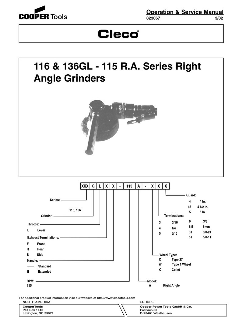
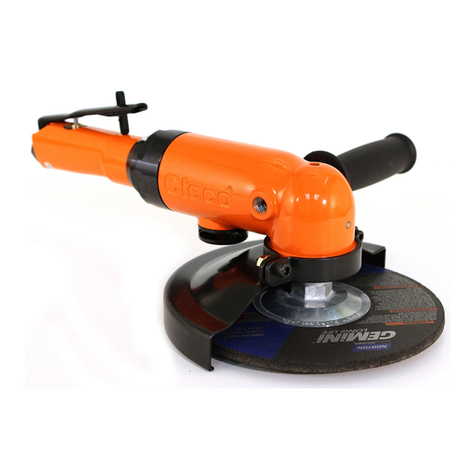
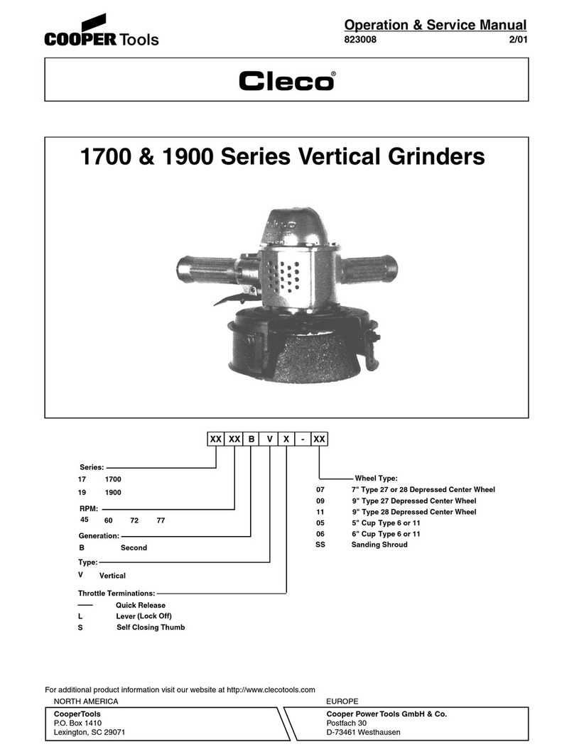
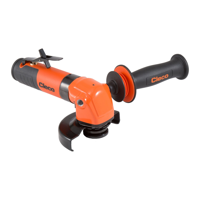
Other Cleco Grinder manuals

Cleco
Cleco 116GLB-135A Installation and operating instructions

Cleco
Cleco 1700 Series Installation and operating instructions

Cleco
Cleco C31 Series User manual

Cleco
Cleco 1660AGL Series User manual

Cleco
Cleco 116 Installation and operating instructions

Cleco
Cleco 15GEL Series Installation and operating instructions

Cleco
Cleco 500 Series User manual

Cleco
Cleco C3120A45-58OH User manual

Cleco
Cleco 1200 Series Service manual