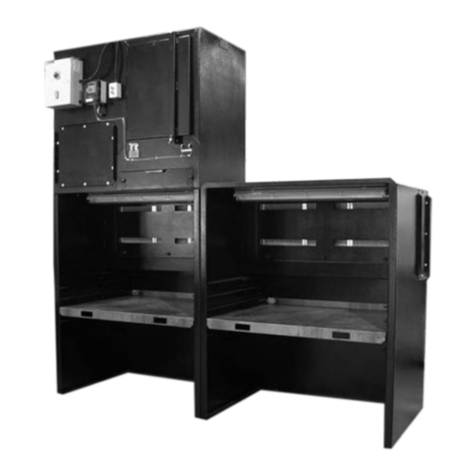
Clemco CDF-4 User manual

CDF MODULAR DUST COLLECTOR
OM 23478
DATE OF ISSUE: 08/12/02
REVISION: D, 11/17
© 2017 CLEMCO INDUSTRIES CORP.
One Cable Car Dr.
Washington, MO 63090
Phone (636) 239-4300
Fax (800) 726-7559
www.clemcoindustries.com
Do not use this
equipment until you
have READ this
MANUAL and YOU
UNDERSTAND its
contents. *
These WARNINGS are
included for the health
and safety of the
operator and those in
the immediate vicinity.
*If you are using a Clemco Distributor
Maintenance and Parts Guide, refer to
the orange warnings insert preceding
the Index before continuing with the
enclosed instructions.
Electronic files include a Preface
containing the same important
information as the orange cover.
WARNING

CDF MODULAR DUST COLLECTOR Page 1
© 2017 CLEMCO INDUSTRIES CORP. www.clemcoindustries.com Manual No. 23478 Rev D
1.0 INTRODUCTION
1.1 Scope of Manual
1.1.1 This manual covers the assembly, installation,
operation and maintenance of Clemco CDF Modular,
Reverse Pulse Dust Collectors. Some equipment may
vary slightly due to size and configuration. Drawings
supplied with this manual apply to the specific dust
collector provided. Use the drawings with the manual, to
assemble the collector, and order replacement parts.
The dust collector is one part of a blast system. This
manual is to be used in conjunction with all other
manuals provided with the equipment.
1.2 Safety Alerts
1.2.1 Clemco uses safety alert signal words, based on
ANSI Z535.4-2011, to alert the user of a potentially
hazardous situation that may be encountered while
operating this equipment. ANSI's definitions of the signal
words are as follows:
This is the safety alert symbol. It is
used to alert you to potential physical
injury hazards. Obey all safety
messages that follow this symbol to
avoid possible injury or death.
NOTICE
Notice indicates information that is considered
important, but not hazard-related, if not
avoided, could result in property damage.
CAUTION
Caution indicates a hazardous situation that, if
not avoided, could result in minor or moderate
injury.
WARNING
Warning indicates a hazardous situation that, if
not avoided, could result in death or serious
injury.
DANGER
Danger indicates a hazardous situation that, if
not avoided, will result in death or serious
injury.
1.3 Table of Contents
Introduction ........................................................... 1.0
Scope of Manual ..................................................... 1.1
Safety Alerts ............................................................ 1.2
General Description ................................................ 1.4
Theory of Operation ................................................ 1.5
Assembly and Installation .................................... 2.0
Footing (Foundation ................................................ 2.1
Individual Module Assembly .................................... 2.2
Connecting Modules Together ................................ 2.3
Anchors ................................................................... 2.4
Exhauster Assembly ................................................ 2.5
Ducting .................................................................... 2.6
Electrical Connections ............................................. 2.7
External Grounding to Earth Ground ...................... 2.8
Compressed Air Connections ................................. 2.9
Install Filter Cartridges .......................................... 2.10
Dust Containers .................................................... 2.11
Operation ............................................................... 3.0
Access Doors .......................................................... 3.1
Initial Start-up .......................................................... 3.2
Operational Start-up ................................................ 3.3
Shutdown ................................................................ 3.4
Adjustments ........................................................... 4.0
Pulse Pressure ........................................................ 4.1
Pulse-Sequence Control Panel and Timer .............. 4.2
Exhauster Damper Setting, Recovery Application... 4.3
Exhauster Damper Setting, Room Ventilation ........ 4.4
Preventive Maintenance ....................................... 5.0
Daily Maintenance ................................................... 5.1
Weekly Maintenance ............................................... 5.2
Service Maintenance ............................................. 6.0
Replacing Filter Cartridge ........................................ 6.1
Season Filter Cartridge ........................................... 6.2
Troubleshooting .................................................... 7.0
Collector not pulsing ................................................ 7.1
Some cartridges not pulsing .................................... 7.2
Pulse is steady stream of air instead of quick pulse .. 7.3
Exhauster not running ............................................. 7.4
Excessive differential pressure ............................... 7.5
No reading on differential pressure gauge .............. 7.6
Dust emitting from exhauster .................................. 7.7
Accessories and Replacement Parts .................. 8.0
Conditioner Cartridge Pre-treat ............................... 8.1
Differential Pressure Indication Panel ..................... 8.2
Common Replacement Parts .................................. 8.3

CDF MODULAR DUST COLLECTOR Page 2
© 2017 CLEMCO INDUSTRIES CORP. www.clemcoindustries.com Manual No. 23478 Rev D
1.4 General Description
1.4.1 CDF Dust Collector modules come in three body
sizes, CDF-4, CDF-6 & CDF-8. The design of the
modules are the same for each body size. Using the
CDF-4 as the base-line, two racks (4 cartridges) are
added to the top to make a CDF-6 module, which
increases the body height accordingly; four cartridge
racks are added on CDF-8 modules.
1.4.2 Each rack contains two cartridges. Each
cartridge has 252 ft2of filter media and is nominally
rated at 500 cfm, rating each rack at 500 ft2and 1000 cfm.
CDF-4: Each module comes with four cartridge racks for
a total of eight cartridges. Each module is nominally
rated at 4000 cfm.
CDF-6: Each module comes with six cartridge racks, for
a total of twelve cartridges. Each module is nominally
rated at 6000 cfm.
CDF-8: Each module comes with eight cartridge racks,
for a total of sixteen cartridges. Each module is
nominally rated at 8000 cfm.
1.4.3 All illustrations used in this manual show CDF-8
modules. Except where noted, assembly and operation
are the same regardless of the body size. A typical
general arrangement is shown in Figure 1.
1.5 Theory of Operation
1.5.1 The exhauster draws dust-laden air through the
ducting from the ventilated area, and through the filter
cartridges. As the air passes through the cartridges, dust
accumulates on the outer surfaces. Cleaned air flows
through the center of the cartridges, through the plenum,
exhaust ducting, and out the exhauster. The
accumulated dust is periodically released from the
cartridges by a pulse of compressed air.
1.5.2 CDF Dust Collectors utilize reverse-pulse jet
cartridge filters. Compressed air used for the pulse
cleaning is released from the pulse manifold by quick-
release diaphragm pulse valves. At regular timed
intervals, the sequence timer sends a signal to one of
the solenoid valves, releasing a pulse of air, which in
turn opens the respective diaphragm valve. The
momentary opening of the valve releases a burst of
compressed air from the manifold to the clean-air side of
the filter cartridges, thus reversing the air flow to remove
accumulated dust.
1.5.3 Each solenoid and diaphragm valve is opened in
sequence until all cartridges have been cleaned once,
and then the cycle is repeated. If the switch on the
sequence panel is kept in the ON position; the sequence
control panel energizes when the exhauster is turned
ON, and stops when the exhauster is turned OFF.
1.5.4 The timers that control the ON and OFF time of
the air pulse are located in the sequence control panel.
The ON time should never be adjusted. The OFF time
controls the length of time between each pulse. The
shorter the OFF time, the more frequent the pulse
cycles.
1.5.5 The differential-pressure gauge shows the
pressure difference between the dirty and clean side of
the filters. The gauge helps determine the proper setting
for the timer OFF time. Refer to Section 4.2.
2.0 ASSEMBLY AND INSTALLATION
WARNING
Weight and bulk of the components require that
erection and placement of the collector
modules be performed by personnel
experienced with handling structural steel, and
able to safely operate material handling
equipment needed to assemble the collector.
Failure to recognize and avoid hazards
associated with handling structural steel could
result in death or serious injury.
NOTICE
All seams assembled on the job site must be
sealed to weather-tight condition. Use mastic
tape, caulking, or gaskets on all seams, as
shown on the assembly drawings.
2.1 Footing (Foundation)
2.1.1 The modules must be installed on sound footing.
WARNING
Footings must be designed by a qualified
engineer. Inadequate footing could result in
hazardous shifting of the collector and ducting,
which could result in death or serious injury.

CDF MODULAR DUST COLLECTOR Page 3
© 2017 CLEMCO INDUSTRIES CORP. www.clemcoindustries.com Manual No. 23478 Rev D
Figure 1
Optional Explosion Vent
Cartridge Cover Plate
Top Exhaust Ducting Plate
Bottom Exhaust Ducting Plate Butterfly Valve
Shown closed
Pulse Manifold
Pulse Manifold
Diaphragm Pulse Valve
Diaphragm Pulse Valves
Two Modules with Long Leg Braces One Module with Short Leg Braces
Leg braces are installed on the manifold side to enable removal of the dust drum
without interference from the pulse mechanism or exhaust ducting.
55 Gallon Dust Drum
Differential-Pressure Gauge
Pulse-Manifold Drain Petcock
Pressure Regulator
Compressed air inlet
Pulse-Sequence Control Panel
Solenoid Bank
Manifold
Interconnecting Hose Inlet Ducting Plate
Inlet ducting may also
enter through the top
if the optional
explosion vent is not
used.
Exhaust Plenum
Inlet Ducting Plate
Inlet ducting may also enter through the top
if the optional explosion vent is not used.
Butterfly Valve
Shown open
Filter Cartridges
Two cartridges in each cartridge rack.
Pulse-Sequence Control Panel

CDF MODULAR DUST COLLECTOR Page 4
© 2017 CLEMCO INDUSTRIES CORP. www.clemcoindustries.com Manual No. 23478 Rev D
2.2 Individual Module Assembly
2.2.1 The modules require field erection of the
structural legs and brace assembly, assembly of the
hopper and body, plus accessories such as ladder,
handrail, exhauster and ducting, and explosion vents.
2.2.2 Erect the collector modules as shown in the
assembly drawings provided. Pay special attention to the
orientation of the inlet and outlet duct openings, access
doors, ladder, handrail, and exhauster location. The
module with the pressure regulator on the pulse manifold
is an end module; refer to the assembly drawing for its
positioning. If the collector is part of a blast room or
automated cabinet, use the general arrangement
drawings for the placement of the components.
2.3 Connecting Modules Together
2.3.1 All fasteners to bolt modules together are
accessible from the outside except for the bolts on the
inside of the exhaust plenum (between the plenum and
cartridge chamber).
2.3.2 Check the assembly drawings for the sealing
material (mastic, weather-strip gasket, caulking, etc.),
and make sure the correct sealing material is in place
before bolting the modules together.
2.3.3 Connect side panels to the end modules using
the seal and fasteners shown on the assembly drawings.
2.4 Anchors
WARNING
All anchors must be calculated and specified by
a qualified engineer. Inadequate anchoring to
the footing could result in hazardous shifting of
the collector and ducting, which could result in
death or serious injury.
2.4.1 Recheck orientation of the dust collector, blast
room and recovery equipment, or other equipment the
collector is ventilating. When satisfied that all are
correctly positioned, anchor modules to the floor with
anchors specified by a qualified engineer. NOTE: If
there is any doubt about the final positioning of the
dust collector, do not remove the lifting equipment
until the collector is fully assembled, connected to
the mating equipment, and ready to be anchored.
2.4.2 After the collector is firmly anchored, remove the
lifting rigging.
2.5 Exhauster Assembly
NOTE: The exhauster is usually floor mounted, and
requires ducting from the collector, and an exhaust stack
with a damper adjustable from 0-80% closed. Some small,
single module collectors may have the exhauster mounted
on the collector body, and do not require additional
ducting.
2.5.1 Anchor the exhauster into position. NOTE:
Positioning of the exhauster must coincide with the
placement of the outlet ducting. Use a temporary anchor
until the ducting is in place.
2.5.2 Attach exhaust stack and damper assembly to
the exhauster outlet.
2.6 Ducting
2.6.1 Clemco Industries Corp. does not usually supply
inlet or exhaust ducting, but does provide a general
arrangement drawing for suggested ducting. The top or
bottom exhaust ducting plate, and inlet ducting plate
may serve as a mounting flange, by cutting an opening
and welding the ducting to the plate.
2.6.2 All ductwork must be designed and installed by
qualified licensed contractors familiar with industrial
ventilation practices, and must conform to applicable
codes. Where state or local codes conflict with one
another or with specifications by Clemco Industries
Corp., the more stringent regulation shall be followed.
NOTICE
All ducts, joints, and connections must be tight.
Any leaks will affect the overall performance of
the system.
NOTICE
Ducting must be supported sufficiently to place
no load on connecting equipment.
2.6.3 Exhaust Ducting. Figure 2
NOTICE
The joint between the duct and exhauster
housing must be flexible, such as canvas or
rubber with band clamps. The ducting must be
self-supporting. NO LOAD IS TO BE APPLIED
TO THE EXHAUSTER BY THE DUCTING.

CDF MODULAR DUST COLLECTOR Page 5
© 2017 CLEMCO INDUSTRIES CORP. www.clemcoindustries.com Manual No. 23478 Rev D
Upper Exhaust Duct Connection
Figure 2
Lower Exhaust Duct Connection
Exhaust Stack
with Damper
Motor
Fan Housing
Exhaust Ducting
Supplied by user
Flex Joint
Ducting Support
Side View
Side View
Exhaust Stack
with Damper
Motor
Fan Housing
Exhaust Ducting
Supplied by user
Flex Joint
Ducting Support

CDF MODULAR DUST COLLECTOR Page 6
© 2017 CLEMCO INDUSTRIES CORP. www.clemcoindustries.com Manual No. 23478 Rev D
Figure 3
2.6.3.1 The illustrations in Figure 2 show typical exhaust
ducting and exhauster arrangements. The illustrations are
for reference only, and are not to be used to fabricate
ducting.
2.6.4 Inlet Ducting
2.6.4.1 The illustrations in Figure 3 show typical inlet
ducting. The illustrations are for reference only, and are
not to be used to fabricate ducting.
2.7 Electrical Connections
WARNING
Shorting electrical components could result in
death, serious electrical shocks, or equipment
damage. All electrical work, or any work done
inside an electrical panel, must be performed by
qualified electricians, and comply with
applicable codes.
Optional Explosion Vent
Inlet ducting entering through the front
Inlet ducting entering through the top
Inlet Ducting Is Supplied By the User
Inlet Ducting is Supplied by the User
Optional Abrasive Resistant Inlet

CDF MODULAR DUST COLLECTOR Page 7
© 2017 CLEMCO INDUSTRIES CORP. www.clemcoindustries.com Manual No. 23478 Rev D
NOTE: Wiring schematics for the pulse-sequence panel,
exhauster motor, control panel and other electrical
accessories are included when accessories are furnished
by Clemco Industries Corp. Refer to the Project Table of
Contents for locations of the electrical wiring schematics.
2.7.1 The dust collector should be controlled by a
separate switch to enable its operation before and after
all other components in the system. Wire all other
components to start in series to prevent overloading any
component. The last segment in the system that the
abrasive reaches should start first and stop last. A
complete blast and recovery facility will have the dust
collector start first, followed by the abrasive cleaner,
bucket elevator, and floor recovery. Shutdown will be in
reverse order.
2.7.2 Electrical connections are required for the
exhauster motor and pulse-sequence control panel. Unless
the collector is operated in conjunction with a Clemco-
provided system control panel, a customer-supplied starter
is also required. When the exhaust fan is connected, make
sure it rotates in the direction of the scroll.
2.7.3 Sequence panel wiring must enter through the
bottom of the panel to avoid potential leakage.
2.8 External Grounding to Earth Ground
2.8.1 To dissipate static electricity, attach an external
grounded wire from an earth ground to the grounding lug
located next to the sequence panel.
2.9 Compressed Air Connections
NOTICE
The air source for the filter pulse must be 35 to
50 degrees Fahrenheit dew point and be free of
any oil contaminants. If line air does not meet
this requirement, an optional air dryer is
recommended. Moisture or oil contaminants in
the pulse system will decrease cartridge life
and filtering efficiency.
2.9.1 CDF-16 and larger dust collectors require an
Interconnecting hose, to supply compressed air between
pulse manifolds. Attach interconnecting hose(s) between
each pulse manifold as shown in Figure 4.
2.9.2 A compressed-air line must be supplied to the
pressure regulator located on the pulse-manifold inlet.
The size of the line depends on the number of modules.
The compressor and piping supplying air to the pulse
manifold must be large enough to provide at least 3 cfm
per cartridge. Purge the air-supply line to remove
moisture or other foreign material before connecting it to
the pulse manifold.
2.9.3 The air line should not be smaller in diameter
than the manifold inlet at the regulator. Note that the
connections shown in Figure 4 are typical; the actual
connections should suit the application. Install unions as
needed to enable removal of items for service or
replacement. NOTE: The regulator is located on the
pulse-manifold to safeguard against an unintentional
change of the pressure setting. If there is no chance of
unauthorized pressure changes, the regulator may be
relocated to a more accessible location.
Figure 4
Interconnecting Hose
Compressed-Air Supply
Pressure Regulator
Air tubing to differential pressure gauge
Pulse Manifold
Diaphragm Pulse Valve

CDF MODULAR DUST COLLECTOR Page 8
© 2017 CLEMCO INDUSTRIES CORP. www.clemcoindustries.com Manual No. 23478 Rev D
2.9.4 Make sure tubing is connected between the
snubber fittings and differential-pressure indication-panel
as shown in Figure 5.
Figure 5
2.10 Install Filter Cartridges, Refer to Figure 6
NOTICE
Use extreme care when handling the cartridges.
Minor dents could cause the cartridge to leak.
2.10.1 Slide two cartridges (gasket end first) over the
support guide.
2.10.2 Place the cover plate (make sure the rim gasket
is in place and the cartridge gasket is toward the inside)
over the support rod.
2.10.3 Place the rubber-backed washer (rubber facing
the cover plate) over the support rod.
2.10.4 Tighten the tensioning knob securely.
2.11 Dust Containers, Refer to Figure 7
2.11.1 Place a dust drum under each hopper and
securely attach a lid to the drums. NOTE: Place the
drums on a pallet if their removal will be with a forklift.
Figure 6
Filter Cartridge
Cartridge Gasket
Cover Plate
Face-gasket must be toward the cartridge
Cover-Plate Face Gasket
Cover Plate
Rubber-Backed Washer
Tensioning Knob
Install both cartridges, gasket end first
Washer and tensioning Knob
Support Guide
Cover-Plate Rim Gasket
Cartridge Gasket
Dirty side of collector
(dust hopper)
Snubber Fitting
1/4Tubing
In-Line Filter
High-Pressure Line
Low-Pressure
Line
Differential-Pressure Gauge
Manifold-Pressure Gau
g
e
To Pulse Manifold

CDF MODULAR DUST COLLECTOR Page 9
© 2017 CLEMCO INDUSTRIES CORP. www.clemcoindustries.com Manual No. 23478 Rev D
2.11.2 Attach a flex hose between the dust drum lid and
pipe at the bottom of the butterfly dump-out valve.
Secure with clamps.
NOTICE
All flex hose connections made at the bottom of
the hopper and the lid must be airtight.
Figure 7
3.0 OPERATION
WARNING
All persons operating this equipment must be
made aware of the hazards of abrasive blasting,
and the handling of toxic materials, including
lead and silica dust. Toxicity and health risk
vary with the type of media and dust generated
by blasting. Identify all material being removed
by blasting, and obtain a Safety Data Sheet
(SDS) for the blast media.
3.1 The dust collector access doors and cover
plates must be closed, and the dump-out valves open,
when the dust collector is in operation.
3.2 Initial Start-up
WARNING
Do not look into the exhauster outlet while the
fan is turning. Injury to the eye or face could
result from objects being ejected from the
exhauster.
3.2.1 Check motor rotation by jogging the starter
(momentarily turn switch ON and OFF). Doing so will
cause the motor to rotate slowly. Look through the slots
in the fan housing on the end of the motor where rotation
of the fan can easily be observed. Proper rotation is
indicated by the arrow on the exhauster housing. The
fan should rotate toward the scroll.
NOTICE
Do not pulse new dust collectors or
replacement cartridges until the cartridges are
seasoned per Section 6.2. Pulsing unseasoned
cartridges could cause premature cartridge
failure or decrease the efficiency of dust
collector.
3.2.2 With the sequence switch OFF, pressurize the
pulse manifold to 100 psi and check pneumatic
connections for leaks.
3.2.3 Turn pulse pressure to 20 psi and switch the
pulse sequence ON. Check the air pulse and sequence
of the diaphragm pulse valves, solenoids, and panel
timer. After all items are checked, turn the sequence
switch OFF. Do not turn the sequence switch ON
until the cartridges are seasoned per Section 6.2.
3.3 Operational Start-Up
3.3.1 Make sure access doors are closed, and slide
gates or dump-out valves are open.
3.3.2 Start the exhauster at the control panel.
3.3.3 Pressurize the pulse manifold and check the
manifold pressure.
Dust Collector Hopper
Butterfly Valve
Hose Clamp
6" ID Flex Hose
Hose Clamp
Dust Drum Lid
55-Gallon Dust Drum

CDF MODULAR DUST COLLECTOR Page 10
© 2017 CLEMCO INDUSTRIES CORP. www.clemcoindustries.com Manual No. 23478 Rev D
3.3.4 Check the differential-pressure gauge; if
differential pressure is greater than 3" water column
(W.C.), turn the sequence switch ON. Leave the switch
OFF if the differential pressure is less than 2” above the
initial reading. NOTE: Optimal filtering efficiency is
obtained with differential pressure between 3" and
5". Adjust pulse pressure (per Section 4.1) and pulse
off time (per Section 4.2) as need to maintain 3" and
5" differential pressure.
NOTICE
Do not turn the sequence switch ON until the
cartridges are seasoned per Section 6.2.
3.4 Shutdown
3.4.1 Allow the system to run until all system
components are empty (refer to the accessory component
operation manuals) and all areas ventilated are free of
airborne dust.
3.4.2 Turn OFF the exhauster.
3.4.3 Shut OFF the air supply to the pulse manifold.
3.4.4 Drain pulse manifolds. The drain cock is mounted
at the bottom of each manifold. Refer to Figure 1. Drain
whenever the air supply is turned OFF.
3.4.5 Close the dust-hopper dump-valves, and empty
all dust receptacles.
4.0 ADJUSTMENTS
4.1 Pulse Pressure
4.1.1 The pulse pressure regulator is located on the
manifold inlet. Start the pulse cycle with the pressure at
70 psi. An additional manifold pressure gauge is
mounted on the differential-pressure panel to enable
monitoring pressure from ground level. The panel is
usually mounted on the back, right side of the collector.
Refer to Figure 1 and Figure 5.
4.2 Pulse-Sequence Control Panel and Timer
4.2.1 The toggle switch mounted on the sequence
control-panel cover enables or disables the pulse
sequencing. If the switch is ON, the pulse sequence will
automatically start whenever the dust collector
exhauster is started. If the switch is OFF, the pulse
sequence will not occur. The switch should be left OFF
(no pulse) until the cartridges are seasoned per Section
6.2.
4.2.2 The timer is factory set at 40 seconds OFF and
approximately 15/100 of a second ON. Every 40
seconds, one filter rack is pulsed in sequence until all
filters have gone through a cycle.
4.2.3 As the filters cake with dust, the pulse may not
clean them well enough to bring the differential pressure
within the optimal range of 3" to 5". A pressure reading
higher than 5" is an indication that more frequent pulse
is needed. When the differential-pressure gauge shows
a constant pressure difference greater than 5", adjust
the OFF time setting to 20 seconds. DO NOT ADJUST
ON TIME. Increasing ON time will consume more air,
but will NOT increase cleaning efficiency.
4.2.4 When the frequency of the pulse cycles will not
lower the differential pressure to less than 5" or if a
decrease in the efficiency is noted, increase pulse
pressure by 10 psi and reset the OFF time to 40
seconds. Continue to alternate OFF time and pressure
(each time pressure in increased reset OFF time to 40
seconds) by 10-psi increments until the maximum of 100
psi and 20 second OFF time is reached.
4.2.5 When the frequency of the pulse cycles and
higher pulse pressure will not lower the differential
pressure below 5.5, or when cfm drops enough to
decrease ventilation, the filter cartridges should be
replaced. Reset the timer OFF time to 40 seconds, and
set pulse pressure to 70 psi. Refer to Section 6.1.
4.3 Exhauster Damper Setting, Recovery
Applications
4.3.1 Refer to the reclaimer manual for damper
settings when the dust collector is used for recovery.
NOTE: When the collector is used for recovery and
ventilation, there is a separate damper for the reclaimer.
4.4 Exhauster Damper Setting, Room Ventilation
4.4.1 Set the exhaust damper to match the ventilation
requirements (feet per minute) for which the blast
enclosure is designed. This information is on the General
Arrangement Drawing for Clemco supplied blast rooms.

CDF MODULAR DUST COLLECTOR Page 11
© 2017 CLEMCO INDUSTRIES CORP. www.clemcoindustries.com Manual No. 23478 Rev D
5.0 PREVENTIVE MAINTENANCE
WARNING
Prior to doing any maintenance or opening the
dust collector, the employer must meet OSHA
standards required but not limited to 29CFR
1910 for
Appropriate Respirator
Protective Clothing
Toxic and Hazardous Substances
Fall Protection
Toxicity and health risk vary with type of dust
generated by blasting. Identify all material that
is being removed by blasting, and obtain a
Safety Data Sheet (SDS) for the blast media.
Waste dust in the collector can cause serious
injury or death through inhalation, absorption,
or consumption. The employer shall meet all
OSHA requirements including those for:
confined space, combustible dust, fall
protection, and hazard communication.
WARNING
Make sure the following conditions are met
before performing any maintenance on the
collector.
Turn OFF compressed air supply and drain
air from pulse manifolds.
Lockout and tagout electrical power.
Failure to observe the above warnings can
result in serious injury from the sudden release
of trapped compressed air.
5.1 Daily Maintenance
5.1.1 Empty dust drums.
NOTE: Check dust drum(s) daily until the dust collection
rate is determined. At that time, setup a program to
empty the drums before they are 2/3 full. Dust should
never accumulate in the hoppers.
5.1.1.1 Close the butterfly valve by pulling the release
lever toward the handle and turn the handle horizontal.
Loosen the clamp ring and remove the drum lid. Remove
the drum from under the collector and empty the dust
into a suitable container. Replace the lid and make sure
the lid clamp ring is secured.
5.1.1.2 Open the butterfly valve by turning the handle to
the vertical position.
5.1.2 Check the exhaust air during a pulse cycle.
5.1.2.1 If dust discharges from the exhauster, filters are
leaking or damaged. Check immediately. To determine
which module is leaking, remove the exhaust ducting
plate and check the inside of the air plenum for dust
trails. NOTE: A small amount of dust egress is normal
for a short period of time when cartridges are new.
5.1.3 Check the differential-pressure gauge at least
once daily, and more often under dusty conditions. Turn
the sequence switch ON or OFF as necessary to maintain
optimal differential pressure (3" to 5"). If the reading is
continually high (greater than 5"), adjust pressure per
Section 4.1 and/or sequence timing per Section 4.2.
5.2 Weekly Maintenance
5.2.1 Check the inside of the collector for moisture. If
moisture is caused by leaks, repair immediately.
5.2.2 Clean the differential-pressure gauge in-line
filter located behind the gauge panel. Refer to Figure 5.
6.0 SERVICE MAINTENANCE
WARNING
Prior to doing any maintenance or opening the
dust collector, the employer must meet OSHA
standards required but not limited to 29CFR
1910 for
Appropriate Respirator
Protective Clothing
Toxic and Hazardous Substances
Fall Protection
Toxicity and health risk vary with type of dust
generated by blasting. Identify all material that
is being removed by blasting, and obtain a
Safety Data Sheet (SDS) for the blast media.
Waste dust in the collector can cause serious
injury or death through inhalation, absorption,
or consumption. The employer shall meet all
OSHA requirements including those for:
confined space, combustible dust, fall
protection, and hazard communication.

CDF MODULAR DUST COLLECTOR Page 12
© 2017 CLEMCO INDUSTRIES CORP. www.clemcoindustries.com Manual No. 23478 Rev D
WARNING
Make sure the following conditions are met
before performing any maintenance on the
collector.
Turn OFF compressed air supply and
drain air from pulse manifolds.
Lockout and tagout electrical power.
Failure to observe the above warnings can
result in serious injury from the sudden release
of trapped compressed air.
6.1 Replacing Filter Cartridge
NOTE: The recommended changeover pressure is 5.5"
W. C. on the differential pressure gauge. Replace
cartridges when pulse pressure is at maximum of 100
psi, sequence OFF time is 20 seconds, and pressure
remains higher than 5.5".
6.1.1 Lock out and tag out the compressed air supply
and electrical power.
6.1.2 Empty the hoppers and dust receptacles.
6.1.3 Remove the knob and rubber-backed washer
securing the cover plate. When removing filter
cartridges, remove one set at a time. Start at the top and
work down.
6.1.4 Rotate the cartridge 180oto remove dust from
the top, and remove the cartridges. A small amount of
sideward force may be necessary to loosen the seal of
the cartridge gaskets. NOTE: Contain dust by sliding a
durable plastic bag over the cartridge as it is removed.
6.1.5 When all cartridges are removed, clean the inside
of the collector to remove loose dust or hardened dust
clods, particularly from the cartridge sealing surface, and
the clean-air side (back) of the cartridge sheet.
6.1.6 Inspect the cover-plate-rim seal, and replace if it
is hardened or damaged.
6.1.7 Install new cartridges per Section 2.10.
6.1.8 Reset timer OFF time to 40 seconds, and set
pulse pressure to 70 psi.
6.1.9 Turn the sequence panel OFF and season
cartridges per Section 6.2.
6.2 Seasoning Cartridges
NOTE: Filter cartridges must be seasoned before the
initial start-up and each time the cartridges are
replaced.
6.2.1 New cartridges must be seasoned before
starting the pulse cycle. Cartridges are seasoned by
letting a layer of dust (dust cake) develop on the outer
surface of the filter media. The dust cake protects the
filter cartridge and enhances the filtering efficiency; it is
the dust cake that actually does the filtering. Use one of
the following methods to season the cartridges.
6.2.2 Seasoning without pre-treat conditioner
6.2.2.1 Operate the dust collector without pulsing
(sequence switch turned OFF) until the dust collector
differential pressure is 2" above the initial reading, after the
exhauster is adjusted to the correct cfm as noted in
Section 4.3 or 4.4.
6.2.2.2 After the differential pressure is reached, set the
pulse sequence timer per Section 6.2.4 and turn the
sequence switch ON to start the pulse.
6.2.3 Seasoning with pre-treat conditioner
6.2.3.1 Before conditioning the filter cartridges, the
following conditions must be met:
1. All cartridges must be installed and the cover plates
tightly secured.
2. The sequence switch turned OFF to prevent pulsing.
NOTE: Do not turn the sequence switch ON again
until the differential-pressure gauge reads 2"
above the initial reading, as noted in Paragraph
6.2.3.5.
3. Make a note of the exhauster damper setting, and
then set it to 50% open.
6.2.3.2 The recommended treatment is 10 lbs. per 1000
ft2(two cartridge racks {4 cartridges}) of filter material.
Conditioner comes 40 lb. sacks. Make sure enough
conditioner is on hand to treat the cartridges as follows:
Model Filter Area Lb. of Conditioner
CDF-4 2000 sq. ft. 40 lbs. (one 40 lb. sack*)
CDF-6 3000 sq. ft. 40 lbs. (one 40 lb. sack*)
CDF-8 4000 sq. ft. 40 lbs. (one 40 lb. sack)
CDF-12 6000 sq. ft. 80 lbs. (two 40 lb. sack*)
CDF-16 8000 sq. ft. 80 lbs. (two 40 lb. sacks)

CDF MODULAR DUST COLLECTOR Page 13
© 2017 CLEMCO INDUSTRIES CORP. www.clemcoindustries.com Manual No. 23478 Rev D
Use conditioner proportionately for larger collectors.
* It does not impair cartridge efficiency by adding
additional conditioner. Once the container is open, use
all the conditioner rather than store an opened container.
6.2.3.3 Start the exhauster and feed the conditioner up
stream of the collector into the ventilation system, such
as ducting access port, blast room outlet baffle or
reclaimer inlet or access door. Feed the conditioner slow
enough so it does not fall out of the air stream at the
intake point.
NOTICE
Do NOT shut OFF the exhauster for six hours
after the treatment or the conditioner may
dislodge from the cartridge media.
6.2.3.4 Reset the damper to 100% open if the collector
is new or to the original setting if replacing cartridges.
6.2.3.5 Begin operation of the system but do NOT turn
the sequence switch ON until the differential-
pressure gauge reads is 2" above the initial reading,
after the exhauster is adjusted to the correct cfm as noted
in Section 4.3 or 4.4. After the 2" difference in pressure is
reached, turn the sequence switch ON to start the pulse
cycle.
6.2.4 Set Pulse Sequence Timer
6.2.4.1 After the differential pressure is reached, set the
pulse pressure to 70 psi per Section 4.1, and set the
timer OFF time to 40 seconds per Section 4.2.
7.0 TROUBLESHOOTING
WARNING
Shut down the collector immediately when dust
emits from the exhauster. Check to make sure
filters are correctly seated and not worn or
damaged. Prolonged breathing of abrasive dust
and blasting by-product dust could result in
serious lung disease or death. Short term
ingestion of toxic dust such as lead, poses an
immediate danger to health. Identify all
materials that are to be removed by blasting,
and obtain a Safety Data Sheet (SDS for the
blast media.
7.1 Collector not pulsing
7.1.1 Check the manifold-pressure gauge. If pressure
is low, check the compressed-air supply; look for a
closed supply valve.
7.1.2 Check function of the pressure regulator located
on the pulse-manifold inlet.
7.1.3 Make sure the sequence switch located on the
panel cover is ON.
7.1.4 Check the fuse in the sequence control panel.
Replace as necessary.
7.1.5 Have a qualified electrician check for electrical
malfunction; check the supply voltage to pulse sequence
board. Check outlet voltage to solenoids.
7.2 Some cartridges not pulsing
7.2.1 Solenoid defective. Have a qualified electrician
check supply voltage to solenoids.
7.2.2 Check the diaphragm pulse valves.
7.2.3 Check for blockage in the tubing between the
diaphragm pulse valve and solenoid assembly.
7.3 Pulse is a steady stream of air instead of a
quick pulse
7.3.1 Check for a leak or split in the tubing between
the diaphragm pulse valve and solenoid assembly.
7.3.2 Solenoid remaining in open position. Have a
qualified electrician check for electrical malfunction, clean,
or replace.

CDF MODULAR DUST COLLECTOR Page 14
© 2017 CLEMCO INDUSTRIES CORP. www.clemcoindustries.com Manual No. 23478 Rev D
7.4 Exhauster not running
7.4.1 Exhauster overload could be tripped. Have a
qualified electrician reset and check for overload.
7.4.2 Make sure that the main disconnect is in the ON
position.
7.4.3 Motor faulty. Have a qualified electrician check for
electrical malfunction.
7.5 Excessive Differential Pressure
7.5.1 Valves may not be pulsing properly. See 7.1.
7.5.2 The differential-pressure gauge lines may be
plugged with dust. Check and clean.
7.5.3 The in-line dust filter may be blocked. Check
and replace.
7.5.4 Snubber fitting blocked with dust. Clean or
replace. Refer to Figure 5.
7.5.5 The sequence OFF time may need adjusting.
Refer to Section 4.2.
7.5.6 Manifold pressure may need to be increased
refer to Section 4.2.4 and 4.2.5.
7.5.7 The filter cartridges may need to be replaced.
See Section 4.2.5 and 6.1.
7.6 No reading on differential-pressure gauge
7.6.1 Check to make sure the low-pressure and high-
pressure lines are not reversed. Refer to Figure 5.
7.7 Dust emitting from exhauster
7.7.1 Damaged filter cartridge. Check for wear or
damage on the filter material, dented ends, and
damaged gaskets.
7.7.2 Loose cover plates. Make sure the cover plate
tensioning knobs are tight.
7.7.3 Cartridges not seasoned. Refer to Section 6.2.
8.0 ACCESSORIES and REPLACEMENT PARTS
Refer to assembly drawings for replacement parts for
specific dust collectors. Any replacement parts that do not
have a stock number should be ordered by referencing the
PRJ (project) number, drawing number, part description,
location, and quantity.
8.1 Conditioner, Cartridge Pre-Treatment
40 lb. sack .................................................23771
8.2 Differential-Pressure Indication Panel
Figure 8
Item Description Stock No.
(-) Indication panel assembly, includes the
mount and items with an asterisk (*) ......15663
1.* Gauge, pressure .......................................19150
2.* Gauge, differential-pressure ......................10188
3. Snubber fitting ...........................................15786
4.* Filter, in-line dust .......................................23415
5.* Fitting, 1/8" NPT straight x 1/8" barb .........11732
6.* Fitting, 1/8" NPT-F x 1/4" tubing ................15703
7.* Elbow, 1/8" x 90obrass st. ........................03993
8.* Fitting, 1/8" NPT elbow x 1/8" barb ...........11733
9.* Fitting, 1/4" NPT elbow x 1/4" tubing ........03428
10.* Tubing, 1/8" urethane; specify ft. req. .......12475
11.* Fitting, 1/4" NPT female bulkhead ............05605
12.* Bushing, 1/4" NPT x 1/8" NPT brass .........02010
13. Tubing, 1/4" OD; specify feet required ......15892
Figure 8
1
2
9
4
3
3
5
10
8
12
13
13
9
11
76

CDF MODULAR DUST COLLECTOR Page 15
© 2017 CLEMCO INDUSTRIES CORP. www.clemcoindustries.com Manual No. 23478 Rev D
8.3 Common Replacement Parts, Figure 9
Item Description Stock No.
1. Valve, 1" diaphragm pulse ........................... 10392
(-) Repair kit for 1" pulse valve (above) ............ 21600
2. Cover plate, cartridge ................................... 23695
3. Seal, cover plate rim..................................... 23742
4. Gasket, cover plate face .............................. 23715
5. Cartridge, filter, 14" x 26";
(2 required per rack) ................................. 23744
6. Knob, 3-arm tensioning ................................ 23741
7. Washer, rubber-backed ............................... 23739
8. Solenoid assembly,
5-valve bank ............................................. 15743
6-valve bank ............................................. 15742
8-valve bank ............................................. 15744
9. Solenoid, individual replacement
for 5 & 8 solenoid bank (15743 & 15744) .....24198
for 6-solenoid bank (15742)....................... 27044
10. Tubing, 1/4" OD; specify feet required ......... 15892
11. Clamp, 6-1/2" ............................................... 00750
12. Hose, 6" flex; 1 ft. required .......................... 12452
13. Fitting, 1/8" NPT elbow x 1/4" tubing ........... 15787
14. Fitting, 1/4" NPT straight x 1/4" tubing ......... 11737
15. Petcock, 1/4" drain ....................................... 01993
16. *Regulator, 1/2" pressure w/gauge................ 01902
17. Fitting, 1/2" NPT x 1/2" male 37o................. 11351
18. Hose end, 1/2" barb x 1/2" female swivel .... 15002
19. Hose, 1/2" ID air; 4 ft. required .................... 12472
20. Gauge, 1/8" cbm pressure (replacement) .... 01908
21. Bushing, 1/4" x 1/8" brass, (not shown) ....... 02010
22. Circuit board, pulse-sequence (not shown)
six-output board ........................................ 15745
ten-output board ....................................... 15746
23. Gasket, 3/16" x 1" adhesive backed;
specify feet required ................................. 00186
24. Valve, 5" butterfly ......................................... 21289
25. Gasket, 5" butterfly valve; 2 required ........... 21455
26. Lid, 55-gallon drum w/6" hose pipe ............. 06633
27. Lock ring, 55-gallon lid ................................. 06634
*Used with up to size CDF-24 dust collector. For
larger size collectors, refer to the parts/assembly
drawing provided with the dust collector.
Figure 9
1 6
7
2
4
5
23
23
23
10
8
10
11
12
13
14
10
15
*16
19
18 17
3
20, 21
9
24
25
22
26
27
This manual suits for next models
4
Table of contents
Other Clemco Dust Collector manuals
Popular Dust Collector manuals by other brands

Grizzly
Grizzly G0860 owner's manual

Delta
Delta 50-760 instruction manual

Makita
Makita DX12 instruction manual

Donaldson Torit
Donaldson Torit Downflo II DFT 2-4 Installation and operation manual

Quatro
Quatro Jet-Stream Operation and maintenance manual

Powermatic
Powermatic PM2200 Operating instructions and parts manual