DAVIS 6464 User manual

USER
MANUAL
Davis Instruments, 3465 Diablo Avenue, Hayward, CA 94545-2778 U.S.A. • 510-732-9229 • www.davisinstruments.com
R
Product numbers 6464 and 6464M
Rain Collector
with Flat Surface Mount


1
Rain Collector (#6464 & 6464M)
This rain collector can be used with Vantage Pro2™
weather stations, including Vantage Pro2, Vantage Pro2 Plus,
and the Sensor Transmitter, as well as an EnviroMonitor Node.
The following instructions assume the rain collector is being used with a
Vantage Pro2 or Vantage Pro2 Plus Integrated Sensor Suite. Refer to the user
manual that came with your station for more information.
Manuals are available online at www.davisinstruments.com
Note: Model number 6464 is factory-calibrated to take rain measurements in 0.01 inches. The
metric version of the rain collector, number 6464M, comes factory-calibrated to take
measurements in 0.2 mm.
Components
• Rain collector cone latched onto base
• Base with tipping mechanism and 40’ (12 m) cable
• Four #8 x 3/4” screws
• Debris Screen
•16 3.5” (9 cm) bird spikes (optional)
RAIN
CONE
40’ Cable
Sensor Cable
Exiting Through
Slot
TIPPING
MECHANISM
Bubble Level
BASE
Finger Grips
Debris Screen
(locks snugly
inside cone)
Latch
Bird Spike
Sockets
3.5”(9 cm)
Bird Spikes (16)
4 #8 x 3/4”
Screws
Cable Tie
Latch
Opening
Drain
Screen

2
Tools and Materials Needed
You may need some of the following tools and materials to install the rain collector.
• Wire cutter
• Drill with 3/32” (2 mm) drill bit
• Medium Phillips screwdriver
• Cable clips or weather-resistant cable ties with screw holes or other means for
mounting
• Small hammer
Prepare the Rain Collector
1. Turn the rain collector upside down. Remove
the cone from the base by rotating the base
until the latches on the cone line up with the
latch openings in the base, then lifting the base
away from the cone.
Tip: It might be easier to remove the cone if you steady it between your knees.
2. Carefully cut and remove
the plastic tie which holds
the tipping spoon in place
during shipping.
Cable
Tie
Sensor
Cable
(black)
+ -
1
1
Note: Be careful to not accidentally cut the sensor cable.
Test the Rain Collector
Before installing the rain collector, test the unit. If you are replacing a rain collector
you previously installed, make a note of the total rainfall amount displayed. You
may want to reenter this amount after you test the rain collector.

3
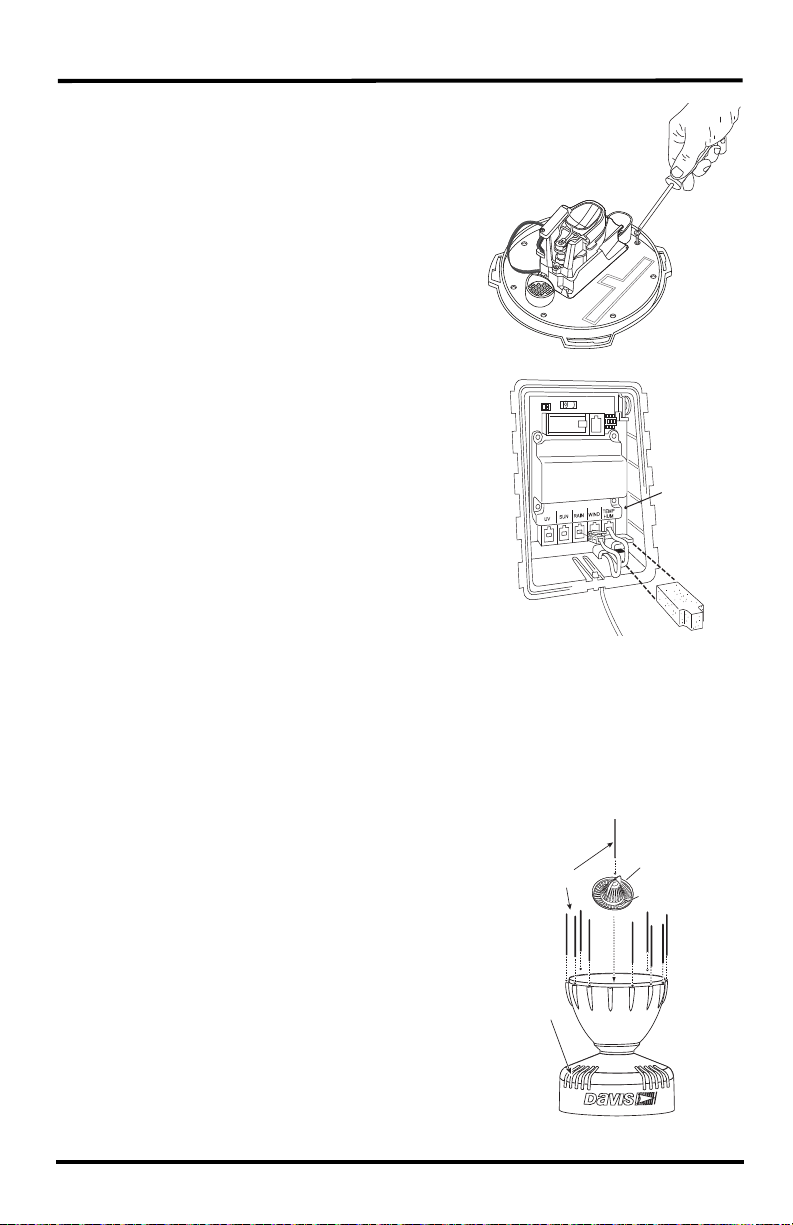
1. Open the transmitter shelter on the sensor suite. Remove the foam insert from the
cable port in the lower right corner and feed the rain collector cable up through
the opening. Plug the cable to the appropriate connector in the sensor interface.
(See illustration on page 5.)
2. Press the RAINDAY button on your console to display rainfall.
3. While watching the display on your console to see if it changes, slowly tip the
spoon until it drops and comes back up. Each tip indicates 0.01" or 0.2 mm of
rain. (It may take up to a minute for the first tip to register at the console.) If the
display does not change, you may be tipping the spoon too quickly. Try again,
more slowly this time. If the rainfall amount displayed on the console increases
by the expected increment (either 0.01" or 0.2 mm) each time you tip the spoon,
your rain collector is working properly.
4. When you have finished testing, separate the rain cone from the base and
disconnect the rain collector cable from the sensor interface in the transmitter
shelter.
Install the Rain Collector
Choose a Location
Keep the following in mind when choosing a location for your rain collector:
• For accurate readings, you must mount the rain collector so that it is level. A
bubble level is built-in to the base to simplify this process.
• Be sure there is an unobstructed path for water runoff from the drain screens.
• The rain collector contains a magnet-operated switch which may not operate cor-
rectly if you mount the rain collector on or near any object which is attracted to a
magnet.
• Exposure to winds can reduce the measured rainfall amounts. Mount the rain collec-
tor where there are no obstructions of rainfall at low angles -- such as trees, houses,
fences -- and as low as possible out of the wind.
• Choose a location which is easily accessible for normal cleaning and is distant from
trees or other sources of heavy pollen or debris.
Note: Climbing on your roof may be hazardous. If you are uneasy about installing your unit
please have a qualified professional complete the installation. Davis specifically disclaims
any liability for injury or loss resulting from the installation or use of the rain collector.
1. Remove the rain collector cone if it is installed.
2. Place the base on the mounting surface and mark the location of the four holes
(the base has eight to choose from) you will use to secure the base.
3. Make pilot holes using a 3/32” (2 mm) drill bit. You should make the pilot holes
about 1/2” (12 mm) deep.

4
4. Fasten the base to the mounting surface
using the #8 x 3/4” screws provided.
5.
Transmitter
Shelter
Sensor
Interface
Foam
Insert
If using with a Vantage Pro2 sensor suite or a
Sensor Transmitter, open the transmitter
shelter on the sensor suite. Remove the foam
insert and feed the rain collector cable up
through the opening. Plug the cable into the
receptacle labeled RAIN. Replace the foam
and close the shelter.
If using with an EnviroMonitor Node, follow
the installation directions on your
EnviroMonitor setup app.
6. To be certain the rain collector is functioning properly after installation, retest.
See “Test the Rain Collector” on page 2.
7. Place the cone back onto the base by putting the latches on the cone into the latch
openings in the base and rotating the cone clockwise until the latches “lock” into
place. As you reattach the cone, make sure to run the cable through the cable slot
int he base, or the cone will not fit snugly against the base.
8. To use bird spikes, insert one spike into each
socket around the rim of the cone. The sockets are
tapered: push firmly or tap lightly with a hammer
for a more secure fit.
Finger
grips
Debris
Screen
Locking
Grooves
Bird
Spikes
Be careful: bird spikes are
sharp.
9. Place the debris screen, pointed end up, into the
cone. Align the locking grooves with the locks
inside the cone and turn to lock the screen in place.
If bird nesting is a problem, you can place a spike
in the hole on top of the debris screen. If you
choose not to install bird spikes, keep the packet of
spikes for possible future use.

5
10.To prevent fraying or cutting of the cable where it is exposed to weather, it is
important that you secure it so it doesn’t whip about in the wind.
Use cable clips or weather resistant cable ties to secure the cable. Place clips or
ties approximately every 3 to 5 feet (1
to 1.6 m). Do not use metal staples or a
staple gun to secure cables. Metal staples, especially when installed with a staple
gun, have a tendency to cut the cables.
Extending Cable Runs
If the cable length supplied with the rain collector is not long enough for your
purposes, you may extend it. The maximum length of cable is 900 feet (274 m). To
extend the cable, purchase standard 4-Conductor Extension Cables from Davis and
connect them to the existing rain collector cable.
Maintaining the Rain Collector
For greatest accuracy, you should thoroughly clean the rain collector at least once or
twice a year.
1. Disconnect the rain collector cable from the sensor interface in the transmitter.
2. Separate the cone from the base.
3. Use a soft damp cloth to clean pollen, dirt, and other debris from the cone, drain
screens, and spoon.
4. Use a pipe cleaner to clear the funnel hole in the cone and the drain screens in the
base. When all parts are clean, rinse with clear water.
5. Reattach the cone and replace the debris screen. Reconnect the rain collector
cable to the sensor interface.
Troubleshooting Guide
? Rainfall is not registering on the console or the console has a large error.
• Check the cable connections from the sensor to the transmitter. Cable connections
account for a large portion of the potential problems. Connections should be firmly
seated in the jacks and plugged in straight. If a reading appears intermittently on
the display as you jiggle the cable, the connection is faulty.
• Make sure there is no magnetic, steel, or iron object near the rain collector.
• Make sure the funnel hole in the cone is clear so water can empty into the spoon.
• Make sure the spoon moves freely and comes back up when tipping. The console
should show an increase in rainfall for each tip of the spoon. (If the spoon does not
move at all, check to make sure you have cut the cable tie that held it in place
during shipping.)
• Make sure the rain collector is mounted so that it is level.

Product Number: 6464 6464M Rain Collector Part Number: 07395.366 Rev A (3/6/19)
This product complies with the essential protection requirements of the EC EMC Directive 2004/108/EC.
Vantage Pro and EnviroMonitor are registered trademarks of Davis Instrments, Hayward, CA.
Copyright © 2019 Davis Instruments Corp. All rights reserved. Davis Instruments Quality Management
System is ISO 9001 certified. Information in this document is subject to change without notice.
3465 Diablo Avenue, Hayward, CA 94545-2778 U.S.A.
510-732-9229 • Fax: 510-732-9188
www.davisinstrumentscom
®
Contacting Davis Technical Support
If you have questions about your rain collector, or encounter problems installing or
operating it, please contact Davis Technical Support.
Note: Please do not return items to the factory for repair without prior authorization.
Online: www.davisinstruments.com
See copies of user manuals, product specifications,
application notes, software updates, and more.
E-mail: [email protected]
Telephone: (510) 732-7814
Monday – Friday, 7:00 a.m. – 5:30 p.m. Pacific Time
Specifications
Sensor Type. . . . . . . . . . . . . . . . . . . . . Tipping spoon with magnetic switch
Output . . . . . . . . . . . . . . . . . . . . . . . . . Contact closure
Attached Cable . . . . . . . . . . . . . . . . . . 40’ (12 m), 4-conductor, 26 AWG
Connector . . . . . . . . . . . . . . . . . . . . . . Modular connector (RJ-11)
Recommended Max.Cable Length . . . 900’ (270 m)
Housing Material . . . . . . . . . . . . . . . . . UV-stabilized ABS plastic
Dimensions with base, no spikes. . . . . 8.75” wide x 9.5” high (22.2 x 24 cm)
Collection Area . . . . . . . . . . . . . . . . . . . 33.2 in2(214 cm2)
Range
Daily Rainfall . . . . . . . . . . . . . . . . . 0.00” to 99.99” (0.0 mm to 999.8 mm)
Total Rainfall. . . . . . . . . . . . . . . . . . 0.00” to 199.99” (0.0 mm to 6553 mm)
Accuracy . . . . . . . . . . . . . . . . . . . . . . . .For rain rates up to 2"/hr (50 mm/hr): ±4% of total or +0.01”
(0.2mm) (0.01" = one tip of the spoon) whichever is greater.
Update Interval . . . . . . . . . . . . . . . . . . . .20 - 24 seconds
Input/Output Connections
Red . . . . . . . . . . . . . . . . . . . . . . . . . Switch terminal
Green & Yellow . . . . . . . . . . . . . . . .Switch terminal
This manual suits for next models
1
Table of contents
Popular Dust Collector manuals by other brands

Oneida Air Systems
Oneida Air Systems 10 HP owner's manual

King Canada
King Canada KC-1101C Service manual

Oneida Air Systems
Oneida Air Systems Dust Deputy AXD002030 owner's manual

Donaldson Torit
Donaldson Torit E-100 Installation and operation manual

Eliet
Eliet C550 ZR manual

Chiko
Chiko CBA-1500AT3-HC-DSA-V1 instruction manual

Simco
Simco VS-1200 user manual

Metabo
Metabo SPA 1200 operating instructions

Rikon Power Tools
Rikon Power Tools POWER TOOLS 60-1750 Operator's manual

HOLZMANN MASCHINEN
HOLZMANN MASCHINEN ABS 3000SE user manual

Donaldson
Donaldson TDS Installation and operation manual

King Industrial
King Industrial KC-2405C instruction manual