National 3402 User manual

HEAVY-DUTY DUST COLLECTOR
INSTRUCTION MANUAL
Caution: Read Manual Before Operating Machine 043014
Rev A


Table of Contents
www.nationalequipment.com Phone: 763-315-53003
Table of Contents .............................................................................................................................................................3
Features and Specifications............................................................................................................................................4
Safety..............................................................................................................................................................................5-9
General Rules for Safe Operation.........................................................................................................................5-6
Grounding.................................................................................................................................................................7
Guidelines for Using Extension Cords......................................................................................................................8
General Safety.......................................................................................................................................................8-9
Machine Operation.........................................................................................................................................................10
Start-Up..................................................................................................................................................................10
Machine Maintenance...............................................................................................................................................11-14
Standard Filter Inspection........................................................................................................................................11
Standard Filter Removal..........................................................................................................................................11
Standard Filter Installation......................................................................................................................................12
HEPAFilter Replacement Procedure......................................................................................................................13
Motor Brushes Inspection.......................................................................................................................................14
Troubleshooting Guide..................................................................................................................................................15
Parts List and Diagrams...........................................................................................................................................16-25
WNS 1000 Motor Deck...........................................................................................................................................16
WNS 2220 MotorAssembly....................................................................................................................................17
WNS 1000 SwitchAssembly..................................................................................................................................18
WNS 2220 SwitchAssembly..................................................................................................................................19
FilterAssemblies ...............................................................................................................................................20-21
Hepa FilterAssembly..............................................................................................................................................22
WNS Series Base...................................................................................................................................................23
Dust Pan LeverAssembly ......................................................................................................................................24
50mm, 70mm & 100mm InletAssembly.................................................................................................................25
Guarantee........................................................................................................................................................................27

Features and Specifications
FEATURES
Product Specifications
Volt. Vac Pres-
sure/Hg MaxAirflow
(cfm) FilterArea
(ft2)
Filter
Efficiency
%@0.3
microns
Sound
Level (dBA) Length Width Height Weight
110 7.1 200 13 99.99% 78 34”
(86.4 cm) 19.5”
(49.5 cm) 44”
(111.76 cm) 99 lb
(44.9 kg)
Two 3.2 HP Motors - two 3.2 HP motors provides high cfm for fast
pick-up of airbone particles.
2” Inlet - 2” inlet attaches 25’crushproof vacuum hose.
Heavy-Duty Locking Casters - allows maneuverability on any sur-
face, with self locking casters.
Steel Handle - easy mobility on congested jobsites.
Hand Lever Filter Shaker - unclogs filter & helps preserve filter life.
Foot Lever - provides dust free, easy emptying.
Dust Pan - 50 lb (9 gallon) “one-step” dustpan removal for fast and
efficient clean-out.
Two 3.2 HP Motors Steel Handle
9 Gallon Dust Pan
2” Inlet
Foot Lever
Heavy-Duty Locking Casters
Hand Lever Filter Shaker

Safety
www.nationalequipment.com Phone: 763-315-53005
GENERAL RULES FOR SAFE OPERATION
READ AND SAVE ALL INSTRUCTIONS FOR FUTURE USE: Before use, be sure everyone operating this equipment reads and
understands this manual as well as any labels packaged with or attached to the tool.
1. KNOW YOUR EQUIPMENT: Readthismanual carefullyto learnequipment applicationsand limitationsaswellaspotential hazards
associated with this type of equipment.
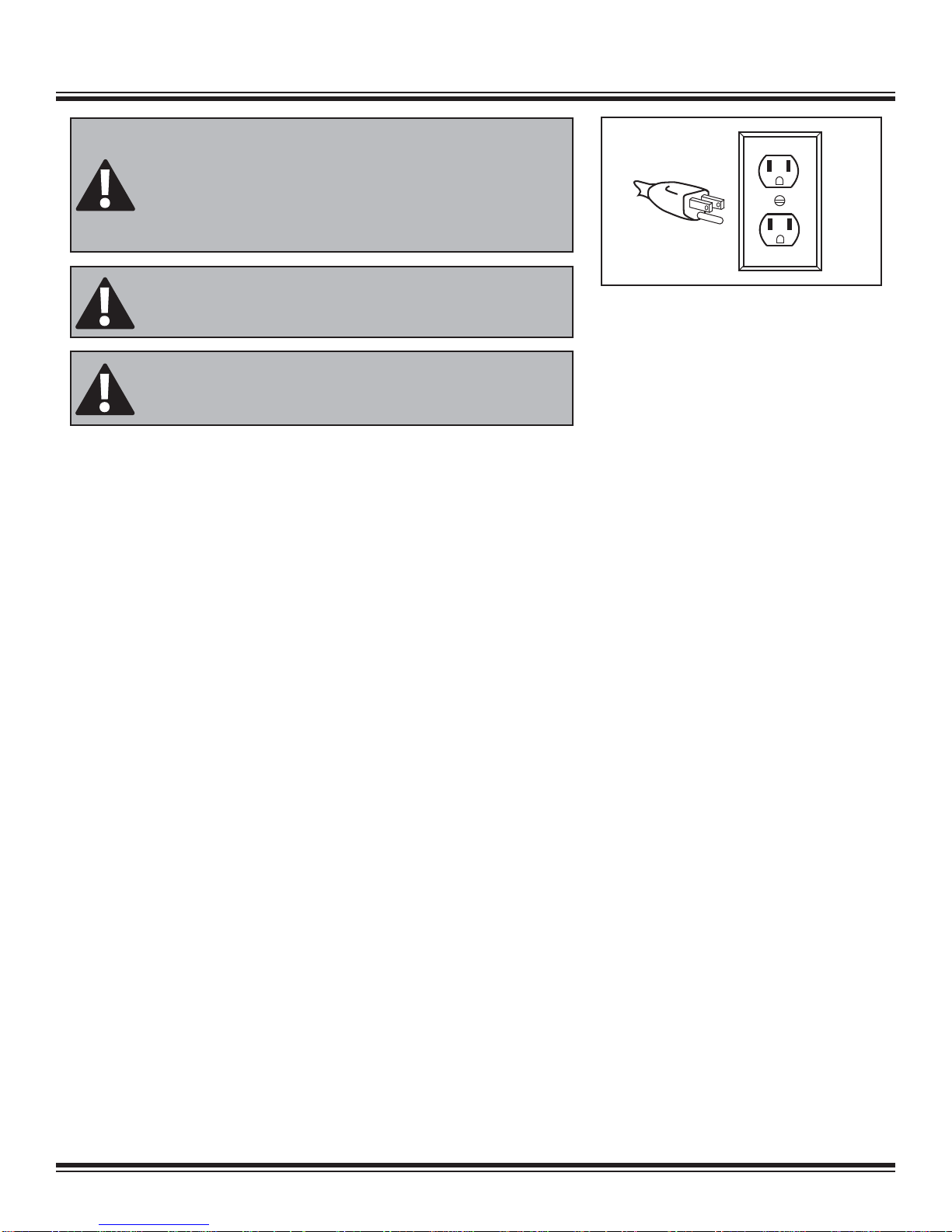
2. GROUND YOUR TOOL: See Grounding (See Page 7).
3. AVOID DANGEROUS ENVIRONMENTS:Donotuse inrain,damporwetlocations,orinthepresenceof explosiveatmospheres
(gaseous fumes, dust or flammable materials). Remove materials or debris that may be ignited by sparks.
4. KEEP WORK AREA CLEAN AND WELL LIT: Cluttered, dark work areas invite accidents.
5. DO NOT USE ON STEPS.
6. DRESS PROPERLY: Do not wear loose clothing.
7. USE SAFETY EQUIPMENT: Everyone in the work area should wear safety goggles or glasses complying with current safety stan-
dards. Wear hearing protection during extended use and a dust mask for dusty operations.
8. KEEP BYSTANDERS AWAY: Children andbystanders should bekeptat asafedistance from thework area toavoiddistracting the
operator and contacting the tool or extension cord. Operator should be aware of who is around them and their proximity.
9. PROTECT OTHERS IN THE WORK AREA: Provide barriers or shields as needed to protect others from debris.
10. USE PROPER ACCESSORIES: Using accessories that are not recommended may be hazardous. Be sure accessories are prop-
erly installed and maintained.
11. CHECK FOR DAMAGED PARTS: Inspect guards and other parts before use. Check for misalignment, binding of moving parts,
improper mounting, broken parts and any other conditions that may affect operation. If abnormal noise or vibration occurs, turn the tool
off immediately and have the problem corrected before further use. Do not use damaged equipment.Tag damaged tools “DO NOT USE”
until repaired. A guard or other damaged parts should be properly repaired or replaced. For all repairs, insist on only identical National
replacement parts.
12. REMOVE ALL ADJUSTING KEYS AND WRENCHES: Make a habit of checking that the adjusting keys, wrenches, etc. are
removed from the tool before turning it on.
13. GUARD AGAINST ELECTRIC SHOCK: Prevent body contact with grounded surfaces such as pipes, radiators, ranges and
refrigerators. Before use always check the work area for hidden wires or pipes. Use a Ground Fault Circuit Interrupter (GFCI) to reduce
shock hazards.
14. AVOID ACCIDENTAL STARTING: Be sure equipmentisturned offbefore plugging itin. Do notusea tool ifthe power switchdoes
not turn the tool on and off.
15. DO NOT ABUSE CORD: Never unplug by pulling the cord from the outlet. Pull plug rather than cord to reduce the risk of damage.
Keep the cord away from heat, oil, sharp objects, cutting edges and moving parts.
16. STAY ALERT: Watch what you are doing, and use common sense. Do not use when you are tired, distracted or under the influence of
drugs, alcohol or any medication causing decreased control.
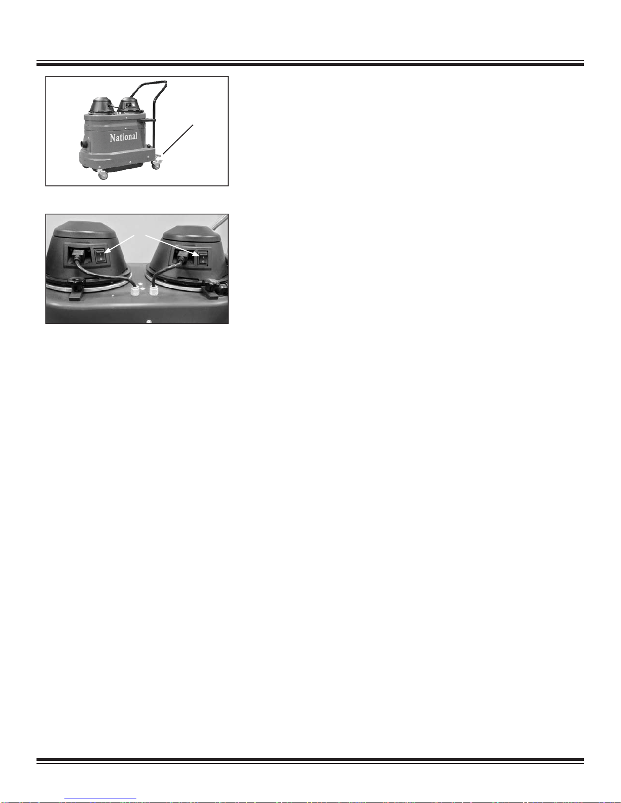
17. STARTING MACHINE: On/off switch must be in off position before connecting to power source.
18. DO NOT DEFEAT OR ALTER A SWITCH OR SAFETY DEVICE
19. UNPLUG EQUIPMENT: When it is not in use, unplug tool before changing accessories or performing recommended maintenance.
20. MAINTAIN EQUIPMENT CAREFULLY: Keep handlesdry, cleanand free from oiland grease. Periodically inspecttool cords and
extension cords for damage. Have damaged parts repaired or replaced.

Safety
21. STORE IDLE EQUIPMENT: When not in use, store in a dry, secured place. Keep away from children.
22. MAINTAIN LABELS AND NAMEPLATES: These carry important information. If unreadable or missing, contact National for a
free replacement.
23. DO NOT DROP: Take caution when moving or transporting.
WARNING: EXPOSURE TO DUST MAY CAUSE RESPIRATORYAILMENTS. USEAPPROVED NIOSH OR OSHARESPIRATOR, SAFETY
GLASSES OR FACE SHIELDS, GLOVESAND PROTECTIVE CLOTHING. PROVIDEADEQUATE VENTILATION TO ELIMINATE DUST, OR TO
MAINTAIN DUST LEVEL BELOWTHE THRESHOLD LIMIT VALUE FOR NUISANCE DUSTAS CLASSIFIED BY OSHA.
WARNING: ALWAYS WEAR RESPIRATOR PROTECTION,APPROPRIATE FOR THEAPPLICATION,AS SPECIFIED BY OSHAREGULA-
TIONSAND YOUR EMPLOYER. NEVER OPERATE OR MAINTAIN EQUIPMENT BEFORE READINGAND UNDERSTANDING THE INSTRUC-
TIONS FOR OPERATION AND MAINTENANCE. OBEYALLSAFETY SIGNSAND INSTRUCTIONS WHILE OPERATING OR MAINTAINING
EQUIPMENT.

Safety
www.nationalequipment.com Phone: 763-315-53007
GROUNDING
Tools marked “Grounding Required” have a three wire cord and three prong grounding
plug. The plug must be connected to a properly grounded outlet (See FigureA). If the tool
should electrically malfunction or break down, grounding provides a low resistance path
to carry electricity away from the user, reducing the risk of electric shock.
The grounding prong in the plug is connected through the green wire inside the cord to
the grounding system in the tool. The green wire in the cord must be the only wire con-
nected to the tool’s grounding system and must never be attached to an electrically “live”
terminal.
Your tool must be plugged into an appropriate outlet, properly installed and grounded in
accordance with all codes and ordinances. The plug and outlet should look like those in
FigureA.
FIG. A
WARNING: IMPROPERLY CONNECTING THE GROUNDING WIRE CAN
RESULT IN THE RISK OF ELECTRIC SHOCK. CHECK WITHAQUALIFIED ELEC-
TRICIAN IF YOUARE IN DOUBTAS TO WHETHER THE OUTLET IS PROPERLY
GROUNDED. DO NOT MODIFYTHE PLUG PROVIDED WITH THE TOOL. NEVER
REMOVE THE GROUNDING PRONG FROMTHE PLUG. DO NOT USETHE
TOOLIF THE CORD OR PLUG IS DAMAGED. IF THE PLUG WILLNOT FITTHE
OUTLET, HAVEA PROPER OUTLETINSTALLED BYAQUALIFIED ELECTRICIAN.
WARNING: ELECTRICAL CORDS CAN BE HAZARDOUS. MISUSE CAN
RESULT IN FIRE OR DEATH BY ELECTRICAL SHOCK. READ CAREFULLYAND
FOLLOWALLDIRECTIONS.
WARNING: RECOMMENDED USE OF GFI RECEPTACLE.

Safety
EXTENSION CORDS
Grounded tools require a three wire extension cord. Double insulated tools can use either a two or three wire extension cord.As the distance
from the supply outlet increases, you must use a heavier gauge extension cord. Using extension cords with inadequately sized wire causes a
serious drop in voltage, resulting in loss of power and possible tool damage.
The smaller the gauge number of the wire, the greater the capacity of the cord. For example, a 14 gauge cord can carry a higher current than
a 16 gauge cord. When using more than one extension cord to make up the total length, be sure each cord contains at least the minimum
wire size required. If you are using one extension cord for more than one tool, add the nameplate amperes and use the sum to determine the
required minimum wire size.
GUIDELINES FOR USING EXTENSION CORDS
• If you are using an extension cord outdoors, make sure it is marked with the suffix “W-A” (“W” in Canada) to indicate that it is acceptable
for outdoor use.
• Be sure your extension cord is properly wired and in good electrical condition. Always replace a damaged extension cord or have it re-
paired by a qualified person before using it.
• Protect your extension cords from sharp objects, excessive heat and damp or wet areas.
• Keep away from water. Do not use if wet.
• Inspect thoroughly before each use. DO NOT USE IF DAMAGED.
• Make sure equipment is OFF before connecting cord outlet.
• FULLY INSERT plug into outlet.
• Do not remove, bend or modify any metal prongs or pins of cord.
• Do not use excessive force to make connections.
• Do not connect a three prong plug to a two-hole cord.
• Avoid overheating. Uncoil cord and do not cover it with any material.
• Do not walk on cord.
• Do not drive, drag or place objects over cord.
GENERAL SAFETY
1. Cables damaged through crushing or splitting can be dangerous if used and should be replaced immediately. Risk of personal injury.
2. Do not connect the machine to an unearthed socket. Risk of personal injury.
3. Make sure the assembly area is firm, so the dust extractor does not tip over. Risk of personal and material injury.
4. Risk of pinching when handling the toggle fastener.
5. Do not vacuum hot or smoldering particles, as the machine can catch fire. If a fire should break out, remove the plug from the socket and
extinguishthefireusingtheavailablefire-fightingequipment. Anappropriate pre-separatorshould beconnected betweenthe suctionpipe
and the dust extractor when sucking up soot, ash and hot materials.
6. The machine must not be used in environments where explosives may be present. Serious risk of explosion.
7. Do not look into the suction pipe or suction hose if blocked. Serious risk of eye injury.
8. Donotdirect thesuction hosetowardsbodypartswhen themachineisrunning. Avoidplacingyour handorotherpartsof thebody against
the suction inlet if the suction hose is not fitted. Risk of personal injury.
WARNING: ELECTRICAL CORDS CAN BE HAZARDOUS. MISUSE CAN RESULT IN FIRE OR DEATH BY ELECTRICAL SHOCK. READ
CAREFULLYAND FOLLOW ALLDIRECTIONS.

Safety
www.nationalequipment.com Phone: 763-315-53009
9. Do not suck up water without use of the water separator. The absolute filter can be damaged.
10. Check, when lifting the machine, that the dust container is empty and that no one else is standing under the lifted machine. Risk of per-
sonal injury and material damage.
CAUTION: MACHINE IS DESIGNED FOR INTERMITTENT USE, I.E. NOTMORE THEN 2 HOURS CONTINUOUSLY.
CAUTION: DISCONNECTTHE MACHINE FROM THE POWER SOURCE BEFOREAND DURING INSPECTIONAND/OR MAINTENANCE.
CAUTION:ADUST MASK SHOULD BE WORN WHEN WORKING WITH USED FILTERS.

Machine Operation
FIG. B
START-UP
1. Pull up on the foot lever to release the dustpan. Check that the dustpan is com-
pletely empty then replace (See Figure B).
2. Connect the machine to the proper power source, as indicated on the machine’s
serial tag.
3. Start the machine by pushing the power switches on the motors to the ON posi-
tion one at a time (See Figure C).
4. Turn the machine off by pushing the power switches on the motors to the OFF
position.
5. The filter should be shaken and the dustpan completely emptied before and after
every use.
FIG. C
Foot lever

Machine Maintenance
www.nationalequipment.com Phone: 763-315-530011
STANDARD FILTER INSPECTION
1. Turn machine off.
2. Knock material off filter via the hand shaker, motorized shaker or reverse pulse.
3. Pull up on foot lever to release dustpan then remove and empty if necessary.
4. Lock rear casters (Figure D) then carefully tip machine back onto the push handle.
5. Remove any material between the pleats, by hand only.
6. Inspect the pleats of the filter for tears and material blockage.
7. Carefully tip machine back onto the casters and replace dustpan.
STANDARD FILTER REMOVAL
1. First follow preceding Filter Inspection procedure to determine if removal is
necessary.
2. Turn the machine on then block the inlet with a flat and rigid material to place the
machine under vacuum pressure.
3. Remove all of the housing-component socket truss screws with a 5/32 hex-
wrench (Figure F).
4. Turn the machine off and disconnect the power source.
5. Separate the motor deck from the housing then disconnect the motor deck ground
wire from the subsequent assembly via the push-on terminal.
6. Disconnect the three power cord wires from the terminal block on the underside
of the motor deck (Figure G).
7. Remove the motor deck.
8. Disconnect the clear differential pressure gage tubes from their respective barbed
fittings if so equipped.
9. Remove the HEPAfilter housing spacer and HEPA adapter assembly if so
equipped; make sure to disconnect the HEPAadapter assembly ground wire via
push-on terminal before removing.
10. Remove the reverse pulse/motorized shaker assembly and housing spacer if
so equipped; make sure to disconnect the component ground wire via push-on
terminal before removing (Figure G).
11. Inspect the top of the filter for material.
12. Remove the filter housing spacer assembly; make sure to disconnect the filter
housing spacer assembly ground wire from the base via push on terminal.
13. Turn the filter housing spacer assembly over on a table then work the filter off the
filter shaker insert.
FIG. D
FIG. E
FIG. G
FIG. H
CAUTION: CLOGGED MATERIAL SHOULD ONLY BE REMOVED BY HAND.
USINGAN OBJECT TO DISLODGE MATERIAL MAYTEAR THE FILTER. CONSULT
YOUR NATIONAL REPRESENTATIVE IF MATERIAL BLOCKAGE IS EXCESSIVE.
FIG. F

Machine Maintenance
FIG. I
STANDARD FILTER INSTALLATION
1. Turn the filter housing spacer assembly over on a table then fit the filter over the
filter shaker insert.
2. Make sure each pleat is fully supported and the ground wire is on the filter side of
the assembly.
3. Connect the filter housing spacer assembly ground wire to the base via the push–
on terminal (Figure H).
4. Seat the filter housing spacer assembly on the base oriented as it was removed.
5. Seat the reverse pulse/motorized shaker assembly and housing spacer (if so
equipped) on the filter housing spacer assembly oriented as removed; make sure
to connect the component ground wire to the filter housing spacer assembly via
push-on terminal.
6. Seat the HEPAadapter assembly and housing spacer (if so equipped) on the pre-
cedinghousingcomponentorientedasremoved;makesuretoconnectthe compo-
nent ground wire to the preceding assembly via push on terminal.
7. Connect the motor deck ground wire to the preceding assembly.
8. Connectthethree power cord wires to thetheirrespective terminals in the terminal
block on the underside of the motor deck.
9. Seat the motor deck on the preceding housing spacer.
10. Connect the clear differential pressure gage tubes to their respective barbed fit-
tings if so equipped.
11. Turn the machine on then block the inlet with a flat and rigid material to place the
machine under vacuum pressure.
12. Secure all of the housing-components then turn the machine off.

Machine Maintenance
www.nationalequipment.com Phone: 763-315-530013
HEPA FILTER REPLACEMENT PROCEDURE
1. Turn the machine on then block the inlet with a flat and rigid material to place the
machine under vacuum pressure.
2. Remove the motor deck socket truss screws.
3. Turn the machine off and disconnect the power source.
4. Unscrew the cable grip in the HEPAfilter housing spacer.
5. Push about a foot of the power cord into the HEPAfilter housing spacer.
6. Separate the motor deck from the HEPA filter housing spacer then disconnect the
motor deck ground wire from the HEPAfilter adapter plate assembly via the push-
on terminal.
7. Disconnect the three power cord wires from the terminal block on the underside of
the motor deck (See Figure K).
8. Remove the motor deck.
9. Remove the four lock nuts retaining the two HEPAfilter brackets.
10. Remove the ring-to-tab terminal, HEPAfilter brackets and HEPAfilter.
11. Center the new filter on the HEPAadapter plate, gasket side down.
12. Positiontheprovidedlengthsof self-adheringflatgasketmaterialontheHEPAfilter
frame (if not already done so) to cushion the HEPAfilter brackets.
13. Replace the HEPA filter brackets and ring-to-tab terminal then thread the locking
nuts over the rods and tighten.
14. Set the motor deck on the HEPAfilter housing spacer.
15. Connectthethree power cord wires to thetheirrespective terminals in the terminal
block on the underside of the motor deck.
16. Connect the motor deck ground wire to the HEPA adapter plate assembly via the
push-on terminal then seat the motor deck on the HEPAfilter housing spacer.
17. Pull any unnecessary slack in the power cord back through the cable grip then
secure the cable.
18. Connect the power source.
19. Turn the machine on then block the inlet with a flat and rigid material to place the
machine under vacuum pressure.
20. Secure the motor deck then turn the machine off.
FIG. J
FIG. K
NOTE: THE DIFFERENTIALPRESSURE GAGE MEASURES THE PRESSURE
ABOVE,AGAINST THE PRESSURE BELOW THE HEPA FILTER, THEREBY
MEASURING THE RESTRICTION OFAIRFLOW THROUGHTHE FILTER. FILTERS
SHOULD BE REPLACED WHEN THE GAGE CONSISTENTLY READS 4 INCHES.
CAUTION: DO NOT OVERTIGHTEN. THE EFFECTIVENESS OFTHE FILTER
MAY BE COMPROMISED IF ITS FRAME IS BENT.

Machine Maintenance
FIG. L
MOTOR BRUSHES INSPECTION
1. Turn the machine off then disconnect the power source.
2. Disconnect both motor terminals.
3. Loosen the motor retaining knobs enough to remove both motors (See Figure L).
4. Remove the 12 screws from the bottoms of the motor assemblies (See Figure M).
5. Remove the plastic motor covers to access the tops of the motors.
6. Remove the 2 metal motor-cap-retaining clips per motor (See Figure N).
7. Carefullydislodgethe plastic motor cap viathebuilt in hooks on bothsidesof each
motor brush. (TIP: Dislodge one side of a cap first, then the other.)
8. Remove the motor brush retainers via the 2 phillips screws per brush.
9. Remove each of the brushes and inspect for excessive or uneven wear.
10. Reverse the procedure to install the brushes.
11. Reassemble and secure both motor assemblies with the 12 motor cover screws.
Do not over tighten the screws, as the cover will crack.
12. Position both motors in the deck and secure with the motor retaining knobs.
13. Connect both motor terminals.
FIG. M
FIG. N
NOTE:ABRUSH SHOULD BE REPLACED IF ITS LENGTH IS LESS THAN 0.25
INCHES.

Troubleshooting Guide
Problem Cause Soulution
Insufficient vacuum pressure Motors are not on and/or working. Turn both motors on, check motor brushes.
Dustpan improperly seated. Remove dustpan, inspect seal and replace
dustpan.
Filter clogged or improperly seated. Follow Filter Inspection Procedure (See Page
11).
Clogged hose. Remove hose and re-inspect vacuum pressure,
if vacuum pressure returns to normal snake
hose.
Unit is improperly sealed. Block the inlet with a flat and rigid material to
place the unit under vacuum pressure then
inspect for air leaks.
Material in exaust or on top side of
filter Poor filter seal or torn filter. Follow Filter Inspection Procedure (See Page
11).
Unusual or high pitch noises Motor bearings or motor bushings Follow relevant motor bushing inspection
procedure, section IV. Check motor bearings for
noise by hand.
Worn or poorly seated seals, retainers improp-
erly installed Block the inlet with a flat and rigid material to
place the unit under vacuum pressure then
remove retainers and turn the unit off. Inspect
the seals for damage, then reseat and secure
components again under vacuum pressure.
www.nationalequipment.com Phone: 763-315-530015

Parts List and Diagrams
1 27015 Housing Cover, Single Motor 1
2 8004 Support Ring for Single Motor 1
3 27007 Separator Plate, WNS Motor Head 1
4 31711 Terminal, 16/14 Gauge, Female Pushon
Blue Nylon 2
5 31011 Terminal, 16/14 Gauge, Pushon,
Female, Non-Insulate 2
6 2509811 Neoprene Sponge Gasket, 3/8” Thick,
5” OD, 2-1/4” ID 1
7 27001 Motor Head, Aluminum 1
8 27004 Gasket for Motor Head 1
9 34817A M6 Blind PEM 4
10 20020 Hold Down Bracket, for WS Motor 2
11 26603 Knob for Motor Hold Down, M6 2
12 27003 #8 x 2” Phil Pan Head, Zinc 6
13 8021 Protection Scree, Motor Head 1
14 27000 Motor, 120V, 1200W 1
15 32987 Sheet Metal Screw, 4.2x16MM 2
16 27012 #8x1/2” Phil Pan Head, Zinc 3
17 27014 Motor Housing, Single 1
18 31503 Terminal, #10 Ring, 16/14 Gauge 1
19 34993 Ground Cable, 16 Gauge, Green 1
20 31711 Terminal, 16/14 Gauge, Female 1
21 34817 M6x20 ULS Allen Head Screw 1
22 34998 Ground Connection, For Bolt 2
23 34876 M6 Lock Nut, Zinc 1
PART# DESCRIPTION QTY PART# DESCRIPTION QTY

Parts List and Diagrams
www.nationalequipment.com Phone: 763-315-530017
1 27015 Housing Cover, Single Motor 2
2 8004 Support Ring for Single Motor 2
3 27007 Seperator Plate, WNS Motor Head 2
4 31711 Terminal, 16/14 Gauge, Female,
Pushon Blue Nylon 4
5 31011 Terminal, 16/14 Gauge, Pushon,
Female, Non-Insulated 4
6 2509811 Neoprene Sponge Gasket 2
7 27001 Motor Head, Aluminum 2
8 27004 Gasket for Motor Head 2
9 34817A M6 Blind PEM 6
10 90223WNS Motor Deck, Red, WNS, 2 Motor 1
11 20020 Hold Down Bracket, For WS Motor 4
12 26603 Knob for Motor Hold Down, M6 4
13 27003 #8x2” Phil Pan Head, Zinc 12
14 8021 Protection Screen, Motor Head 2
15 27002 Motor, 120V, 1000 Watt 2
16 116549-13 Motor, 240V, 1200 Watt 2
17 32987 Sheet Metal Screw, 4.2x16MM 4
18 27012 #8x1/2” Phil Pan Head, Zinc 6
19 27014 Motor Housing, Single 2
PART# DESCRIPTION QTY PART# DESCRIPTION QTY

Parts List and Diagrams
1 27017 Switch, Toggle, WS, 1000/1200 1
2 25211 Male IEC Plug 1
3 34905A Ground Wire From Plug to Motor 2
4 2005531 Power Cord, 12/3 SJO w/Molded 110V
Plug 1
5 25209 Female IEC Plug 1
PART# DESCRIPTION QTY PART# DESCRIPTION QTY

Parts List and Diagrams
www.nationalequipment.com Phone: 763-315-530019
1 27017 Switch, Toggle, WS 1000/1200 2
2 25211 Male IEC Plug 2
3 34905A Ground Wire from Plug to Motor 4
4 34993 Ground Cable, 16 Gauge, Green 2
5 34960 PG 09 Cable Grip 2
6 25048 #8-32x3/4 Phillips Flat Head 2
7 25049 #8-32 Hex Nut 2
8 34961 Strain Relief, 90 Deg, 1/2” NPT 1
9 2005531 Power Cable 1
10 25210 Female IEC Plug w/12” Wire 2
11 21095 Wire Nut, Twisting 3
12 32999 Junction Box 1
13 32989 #10-16x5/8 Hex Washer Tek, Zinc 2
PART# DESCRIPTION QTY PART# DESCRIPTION QTY
Table of contents
Popular Dust Collector manuals by other brands

King Industrial
King Industrial KC-3108C instruction manual

Jet
Jet JDC-510 Operating instructions and parts manual

Powermatic
Powermatic PM1300TX-BK Instructions and parts manual

Husqvarna
Husqvarna DC 6000 Operator's manual

Oneida Air Systems
Oneida Air Systems Dust Deputy AXD002030 owner's manual

Oliver
Oliver 7155 owner's manual

Chiko
Chiko CBA-1500AT3-HC-DSA-V1 instruction manual

Oneida Air Systems
Oneida Air Systems Supercell Mobile owner's manual

belfab
belfab JDW Instruction and maintenance manual

TSI Instruments
TSI Instruments PAN231 Series Operation and service manual

Powermatic
Powermatic 75 Instruction manual & parts list

Jet
Jet JDC-501 Operating instructions and parts manual