Peachtree Big Sweep User manual

Version 1.0
Big Sweep
Lathe Dust Catcher System
Ear Protection Respiratory
Protection
Disconnect
saw from
power source
before tting
or removing
insert.
Always wear
proper eye
protection
when working
with machinery
and tools.
Always wear
proper ear
protection when
working with
machinery.
Always wear
proper respiratory
protection when
working near
airborne dust
particles.
Use caution when
handling sharp objects
(saw blades, router bits,
drill bits and so on).
Use protective gloves
whenever possible.
Please read and fully understand
any and all safety materials that
came with your power tools or
machinery before operation. Always
follow all safety guidelines set in
place by the power tool or machine
manufacturer.
Safety First
Fine sawdust from sanding your turning projects on your lathe is not only messy, it’s also a health risk that
should not be taken lightly. The Big Sweep Lathe Dust Catcher System is the perfect solution. It’s easy to install
and even easier to adjust to the exact position you need. It works with large or small projects and can be used
horizontally or vertically depending on your project shape. When not in use it can be quickly moved out of the
way so it does not interfere. Works on any size lathe with a unique clamp mounting system. Minimize the dust
and breathe a little easier using the Big Sweep Dust Catcher System
BIG SWEEP Lathe Dust Catcher System

12 3 4 5 6 7 8 9
910
13
13
8
9
512
Head Assembly Parts List
Please note that the parts listed
below reference all three diagrams
shown on this page.
Track & Tube Mount Assembly
20
2
19
18
9
11
17
16
2
2
15
12
14
21
7/8"tube insert this hole
11
Qty.No. Description
Dust Hood1 1
5
1
1
1
1
3
2
3
4
5
6
7
1/4”x20 round knob
C-connect clip
C-connect base
1/4”x20x1-1/2” Bolt
Black Bushing
Small Silver 1/4”Washer
1/4”x20 lock nut8 2
4
1
1
1
2
9
10
11
12
13
Black 1/4”Washer
1/4”x20 ratchet knob
7/8” Lower Tube
1/4”x20x3/4” bolt
3/4” Upper Tube
1/4”x20x1” t-bolt14 2
1
1
1
1
1
1
15
16
17
18
19
20
Aluminum L Base
5/16”x18x3/4” Bolt
Tube Connector Clip
Large Silver 5/16”Washer
1/4”x20x1” Bolt
5/16”x18 Round Knob
Mounting - T - Track21 1
3
3
3
22
23
24
T - Track Mounting Block
Locking Set Screw
1-1/4” Studded T - Knob
1
25 4” Hose Clamp*
1
26 4” Flex Hose*
Big Sweep Exploded Parts View
*Not shown in drawings
Lathe Mount Assembly
22
21
23
24

Step 1.
Part Idencaon
Layout out all of the parts and pieces that came with the
big sweep. Using the exploded parts view on the previous
page, idenfy each of the parts and the quanes. We
will be using the reference numbers in exploded parts
view throughout the instrucon process.
Step 2
Assemble the Track Mounng Blocks (22)
To do this, thread a Studded T-knob (24) into the upper
hole on one of the blocks as shown. Do not thread all
the way through. Next, thread a locking set screw (23)
into the lower hole as shown. Do not thread all the way
through. Once you are completed with the rst block,
repeat this process for the other two blocks.
Step 3
Install T-Track Mounng Blocks
Slide the T-Track Mounng Blocks (22) on to the single
sloed side of the Mounng Track (21) making sure that
each block is facing the same direcon as shown above.
Step 4
Aach the Track and Mounng Block Assembly
Please note that all lathes are dierent as far as shape.
The blocks are designed to slide along the track to adapt
to the shape of your lathe. Start at one end of the track
and secure the block to your lathe by ghtening the
Studded T-knob (24). Aach and secure the next block fol-
lowed by the third block. Lock the track in place by ght-
ening the Set Screws (23) with a philips head screw driver.
Step 5
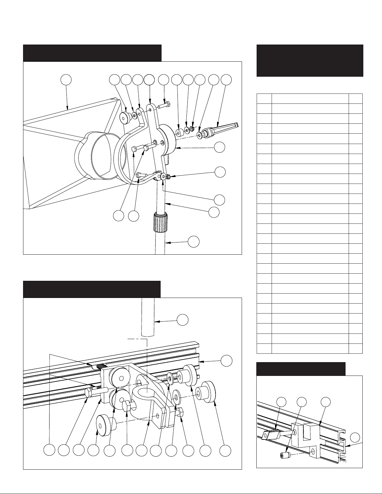
Assemble the Lower Support Bracket Assembly.
A.Insert the 5/16” (16) bolt through the center hole of
the Tube Connector Clip (17) . A. Aach the Tube Connec-
tor Clip (17) to the Aluminum L Base (15) using the 5/16”
bolt (16) with washer (19) and 5/16” Round Knob (20). B.
Using a ¼”x 20x ¾” bolt (12), insert bolt as shown and se-
cure with ¼” x 20 Round Knob (2) and Washer (9). C. Next,
using a long ¼” x 20x 1” bolt (19), insert into clamp end of
the Tube Connector Clip, secure with a 1/4” x 20 knob (2).
D. Insert a T-bolt (14) into one of the holes on the Alumi-
num L Base at the boom, thread on with a 1/4”x20 (2)
round knob. Repeat this process (D) for the other hole at
the boom of the Base.
Studded T-Knob
Locking
Set Screw
D.T-Bolt
A.5/16” Bolt
B.3/4” x 20 Bolt
C.1”x 1/4” x 20 Bolt
A.5/16” Knob
& Washer
C.1/4” x 20
Knob & Washer
D.1/4” x 20
Knob
B.1/4” x 20
Knob & Washer
Mounting Track
1
2
3

Step 6
Aach Tube to Conncect Clip
Insert 7/8” Lower Tube (11)
into the Tube Connector Clip
as shown in the image to the
le.
Step 7
Aach Base Assembly
Insert the both T-bolt heads into the Mounted T-Track Rail
and secure in place by ghtening the two knobs as shown
above.
Step 8
Aach C-Connect Clip to C-Connect Clip Base
Using the 1/4x20x1” Bolt (12), washer (9) and lock nut (8),
aach the c-connect clip (4) to the c-connect base (3) as
shown above. Adjust the ghtness of the locking nut so
that the c-connect clip pivots smoothly on the base.
Step 9
Aach C-Connect Base to 3/4” upper tube.
Please note that you can aach this to either side of the
upper tube depending upon your preference. Insert both
1/4”x20x1¼” (5) Bolts through the two center holes on
the c-connect base and take the c-connect assembly with
the two bolts and insert into the head on the 3/4” Upper
Tube. Place the black washer (9) on the outer bolt and
secure with the 1/4”x20 ratchet knob (10). Place the Black
Bushing (6), small silver washer (7) onto the center bolt.
Secure with locking nut (8). Adjust the ghtness of the
locking nut so that the c-connect base pivots smoothly on
the head of the 3/4” Upper Tube.
Tighten Both Knobs

Step 11
Aach Hose to Dust Hood
Aach the 4” Hose to the Dust Hood. Making sure the
hose is bued up ghtly against the back of the dust
hood. Secure the Dust Hood with the supplied hose clamp
as close to the dust hood as possible as shown above.
You are now ready to start using your new Big Sweep
Dust Collecon System. There are many ways to adjust
the Big Sweep to achieve the best sucon for any proj-
ect. Your Big Sweep system is designed to pivot, lt,
swivel and slide into any poson you need.
CAUTION:
Never use your Big Sweep system unless all adjustable
points are ght and secure. Failure to do so may allow
your system to fall into your spinning project. This may re-
sult in injury or possible damage of your big Sweep which
is not covered by warranty
Step 12
Aach Hose and Hood
Place the Dust Hood and Hose assembly into the c-con-
nect base and clip assembly so that the dust hood mouth
is facing the same direcon as the at part of the c-con-
nect base. Secure c-connect clip with 1/4”x20x1½”(5)
bolt, washer (9) and 1/4”x20 round knob. Adjust the loca-
on of the dust hood so that the c-connect clip is clamp-
ing around the base of the dust hood rmly.
Step 10
Aach Top Assembly to Base Assembly
Insert 3/4” upper tube into 7/8” lower tube and secure in
place ghtening the locking collar.
Secure
with
Locking
Collar
Table of contents
Popular Dust Collector manuals by other brands

Donaldson
Donaldson DFPRE 4 Series Installation, operation and maintenance manual

Craftsman
Craftsman 351.223140 Operator's manual

UAS
UAS C Series owner's manual

Yazoo/Kees
Yazoo/Kees Z9 Commercial Collection System Z9A Operating and parts manual

Grizzly
Grizzly G0637 owner's manual

Hercules
Hercules SDS-PLUS HA027 Owner's manual & safety instructions

Trelawny
Trelawny A45 Operation and maintenance manual

DustEZE
DustEZE EC-560 Booklet

Minnich
Minnich A-1CL Operators & service manual

Nation Flooring Equipment
Nation Flooring Equipment 3474-L-SUN instruction manual

King Industrial
King Industrial KC-7200C instruction manual

Smith
Smith MV1000 Parts and operation manual