Clemco TLR-50 User manual

TLR-50, 1/2-INCH
PNEUMATIC REMOTE CONTROLS
O. M. 03358
DATE OF ISSUE: 04/01/77
REVISION: I, 08/13
© 2013 CLEMCO INDUSTRIES CORP.
One Cable Car Dr.
Washington, MO 63090
Phone (636) 239-4300
Fax (800) 726-7559
www.clemcoindustries.com
Do not proceed with
these instructions
until you have READ
the orange cover of
this MANUAL and YOU
UNDERSTAND its
contents. *
These WARNINGS are
included for the health
and safety of the
operator and those in
the immediate vicinity.
*If you are using a Clemco Distributor
Maintenance and Parts Guide, refer to
the orange warnings insert preceding
the Index before continuing with the
enclosed instructions.
Electronic files include a Preface
containing the same important
information as the orange cover.
WARNING

PREFACE
[I]
• Employers are responsible for identifying all job site hazards, educating and training all persons who will operate and
maintain these products, and ensuring that all blast operators and their assistants understand the warnings and
information contained in these instructions relating to safe and proper operation and maintenance of this equipment.
• Serious injury or death can result from failure to comply with all Occupational Safety and Health Administration
(OSHA)regulations and all manufacturer’s instructions.
• This equipment is not intended for use in any area considered hazardous per National Electric Code NFPA 70 2011,
Article 500.
• Read this document and follow all instructions before using this equipment.
OSHA regulations relating to abrasive blasting are contained in the Code of Federal Regulations, Title 29 (29 CFR 1910 General Industry;
1915 Maritime; 1926 Construction). The most pertinent include: 1910.94 Ventilation, 1910.95 Occupational Noise Exposure, 1910.132
Personal Protective Equipment, 1910.133 Eye and Face Protection, 1910.134 Respiratory Protection, 1910.135 Head Protection,
1910.244 (b) Remote Controls. Consult www.osha.gov for complete information.
NO
T
I
C
E
TO
PURCHASERS
AND
U
SE
R
S
OF
OUR
P
R
ODU
C
T
S
AND
T
H
I
S
I
N
F
O
R
M
A
T
I
ON
A
L
M
A
T
E
R
I
A
L
Clemco proudly provides products for the abrasive blast
industry and is confident that industry professionals will use
their knowledge and expertise for the safe and efficient use of
these products.
The products described in this material, and the information
relating to these products, are intended for knowledgeable,
experienced users.
No representation is intended or made as to: the suitability of
the products described here for any purpose or application, or
to the efficiency, production rate, or useful life of these
products. All estimates regarding production rates or finishes
are the responsibility of the user and must be derived solely
from the user’s experience and expertise, not from information
contained in this material.
It is possible that the products described in this material may
be combined with other products by the user for purposes
determined solely by the user. No representations are
intended or made as to the suitability of or engineering
balance of or compliance with regulations or standard practice
of any such combination of products or components the user
may employ.
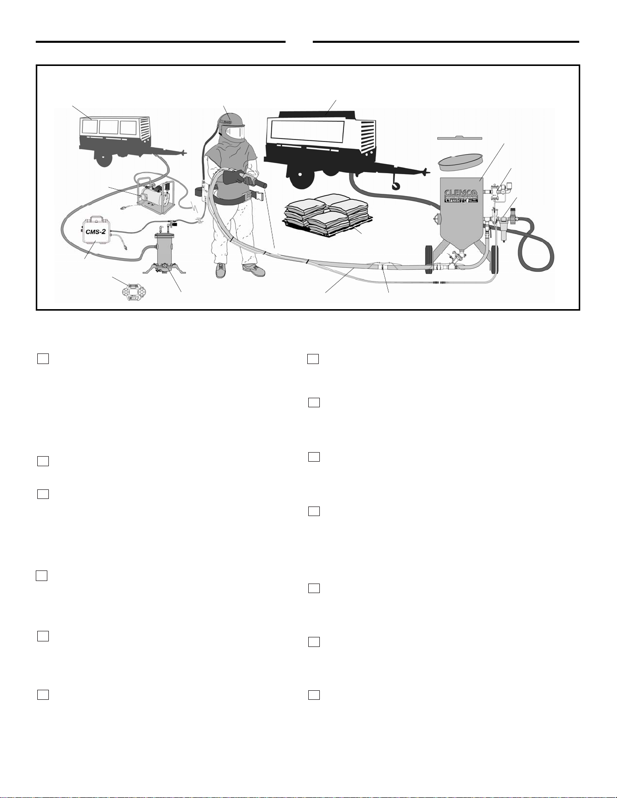
Abrasive blast equipment is only one component of an
abrasive blasting job. Other products, such as air
compressors, air filters and receivers, abrasives, scaffolding,
hydraulic work platforms or booms, equipment for lighting,
painting, ventilating, dehumidifying, parts handling, or
specialized respirators or other equipment, even if offered by
Clemco, may have been manufactured or supplied by others.
The information Clemco provides is intended to support the
products Clemco manufactures. Users must contact each
manufacturer and supplier of products used in the blast job for
warnings, information, training, and instruction relating to the
proper and safe use of their equipment.
GENERAL INSTRUCTIONS
This material describes some, but not all, of the major
requirements for safe and productive use of blast machines,
remote controls, respirator systems, and related accessories.
All equipment and accessories must be installed, tested,
operated and maintained only by trained, knowledgeable,
experienced users.
The blast operator and all workers in the vicinity must be
properly protected from all job site hazards including those
hazards generated by blasting.
Work environments involving abrasive blasting present
numerous hazards. Hazards relate to the blast process from
many sources that include, but are not limited to, dust
generated by blasting or from material present on the surface
being blasted. The hazards from toxic materials may include,
but are not limited to, silica, cyanide, arsenic, or other toxins
in the abrasives or in the coatings, such as lead or heavy
metals. Other hazards from toxins include, but are not limited
to, fumes from coating application, carbon monoxide from
engine exhaust, contaminated water, chemicals or asbestos.
In addition, physical hazards that may be present include, but
are not limited to, uneven work surfaces, poor visibility,
excessive noise, and electricity. Employers must identify all
job site hazards and protect workers in accordance with
OSHA regulations.
Never modify Clemco equipment or components or
substitute parts from other manufacturers for any Clemco
components or parts. Any unauthorized modification or
substitution of supplied-air respirator parts violates OSHA
regulations and voids the NIOSH approval.
IMPORTANT
Contact Clemco for free booklets:
Blast Off 2 – Guide to Safe, Productive, and Efficient Abrasive
Blasting, and Abrasive Blasting Safety Practices – Guide to Safe
Abrasive Blasting.
Clemco Industries Corp. One Cable Car Drive Washington MO 63090
Tel: 636 239-4300 — Fax: 800 726-7559
Website: www.clemcoindustries.com

PREFACE
[II]
OPERATIONAL INSTRUCTIONS
OPERATOR SAFETY EQUIPMENT
OSHA regulation 1910.134 requires appropriate respiratory protection for blast operators and workers in
the vicinity of blasting. These workers must wear properly-fitted, properly-maintained, NIOSH-approved,
respiratory protection that is suitable for the job site hazards. Blast respirators are to be worn only in
atmospheres not immediately dangerous to life or health from which wearers can escape without use of
the respirator.
The employer must develop and implement a written respiratory protection program with required
worksite- specific procedures and elements for required respirator use. The employer must provide
effective training to employees who are required to use respirators. The training must be comprehensive,
understandable, and recur annually, and more often if necessary.
NEVER use abrasives containing more than one percent crystalline silica. Fatal diseases, such as silicosis,
asbestosis, lead or other poisoning, can result from inhalation of toxic dusts, which include, but are not
limited to, crystalline silica, asbestos, and lead paint. Refer to NIOSH Alert 92-102; and OSHA CPL 03-00-007:
“National Emphasis Program – Crystalline Silica”, in which OSHA describes policies and procedures for
implementing a national emphasis program to identify and reduce or eliminate health hazards from exposure
to crystalline silica. Numerous topics associated with the hazards of crystalline silica in silica blasting sand
can be found on http:// osha.gov/. Clemco urges users of silica blasting sand to visit this website, and read
and heed the information it contains.
Always make sure the breathing air supply (respirator hose) is not connected to plant lines that supply
gases that include, but are not limited to, oxygen, nitrogen, acetylene, or other non-breathable gas. Never
modify or change respirator air line connections without first testing the content of the line for safe
breathing air. Failure to test the line may result in death to the respirator user.
• Breathing air quality must be at least GradeD,
as defined by the Compressed Gas Association
specification G-7.1, per OSHA Regulation 29 CFR
1910.134. When compressed air is the breathingair
source, a Clemco CPF (suitable sorbent bed filter)
should be used. Respirator hose connecting the
respirator to the filter must be NIOSH approved.
Non- approvedhose can cause illness from
chemicals employed to manufacture the hose.
• All workers must always wear NIOSH-approved
respirators when any dust is present. Exposure to
dust can occur when handling or loading abrasive,
blasting, cleaning up abrasive, or working in the
vicinity of blasting. Before removing the respirator,
test the air with a monitoring device to ensure it is
safe to breathe.
• Clemco respirators DO NOT removeor protect against
carbon monoxide or any other toxic gas. Monitoring
devices must be used in conjunction with the respirator to
ensure safe breathingair. Always locate compressors and
ambient air pumps where contaminatedair will not enter
the air intake.
• Always use Clemco lenses with Clemco respirators;
installing non-approvedlenses voids the NIOSH approval.
Respirator lenses aredesigned to protect the wearerfrom
rebounding abrasive; they do not protect against flying
objects, heavyhigh-speed materials, glare,liquids, or
radiation.
INDUSTRY ORGANIZATIONS
For additional information, consult:
Occupational Safety and Health Administration (OSHA) - www.osha.gov
Compressed Gas Association (CGA) - www.cganet.com
TheSociety for Protective Coatings (SSPC) - www.sspc.org
National Association of Corrosion Engineers (NACE) - www.nace.org
American Society for Testing and Materials (ASTM) - www.astm.org
National Institute of Occupational Safety and Health (NIOSH) - www.niosh.gov
American National Standards Institute (ANSI) - www.ansi.org

PREFACE
[III]
BLAST MACHINES AND REMOTE CONTROLS
OSHA regulation 1910.169 describes the necessity of pressure relief valves on compressed air equipment. Do not
operate blast machines with air compressors that are not equipped with properly functioning pressure relief valves.
OSHA regulation 1910.244(b) requires the use of remote controls on blast machines.
Serious injury or death can result from many sources, among them:
Involuntary activation of the remote controls. Never modify or substitute remote control parts; parts are not
compatible among different manufacturers. Welding hose is not suitable for remote control hose. Its ID and material
composition make it unsafe for remote control use.
Exceeding the maximum working pressure. Clemco blast machines are built to ASME-code and carry a ‘U’ or ‘UM’
stamp, and National Board/serial number. Every machine is marked with its maximum working pressure. Never
exceed the maximum working pressure limits of the blast machine.
Uncontrolled blast stream. High-velocity abrasive particles will inflict serious injury. Always point the blast nozzle
in the direction of the blast surface only. Keep unprotected workers out of the blast area.
Welding on the blast machine. Never weld on the blast machine; welding voids the National Board approval and
may affect the dimensional integrity of the vessel.
Moving the blast machine. Never manually move a blast machine containing abrasive, any machine containing
abrasive must be moved with appropriate mechanical lifting equipment.
HOSES, COUPLINGS, AND NOZZLE HOLDERS
The inside diameter (ID) of air hoses, fittings, and connections
should be at least four times larger than the nozzle orifice size. Blast
hose ID should be three to four times the size of the nozzle orifice.
Example: a #6 nozzle (3/8” diameter orifice) calls for 1-1/2” ID blast
hose and 1-1/2” ID or larger compressor hose. All hose runs should be
kept as short as possible and run in as straight a line as possible to
reduce pressure loss.
To install, squarely cut the end of the hose so that it fits snugly
against the coupling or hose end shoulder. Always use the screws
recommended by the manufacturer ensuring that they do not
penetrate the inner wall. Make sure the couplings tightly fit the hose.
Install cotter pins at every connection or use couplings with built-in
lock-springs to prevent disengagement. Install safety cables at all
connections to prevent whipping if hoses disengage or blow out.
MAINTENANCE AND REPAIR
Completelyreadand follow all service instructions and recommended maintenance intervals. Always shut off compressor and
depressurize blast machine beforeperforming any maintenance. At everyservice interval, clean all filters, screens, and alarm systems. If
spring-loaded abrasive valves areused, always cage spring beforedisassembly.
WARRANTY
The following is in lieu of all warranties, express, implied or statutory, and in no event shall seller or its agents, successors, nominees or
assignees, or either, be liable for special or consequential damage arising out of a breach of warranty. This warranty does not apply to any damage or
defect resulting from negligent or improper assembly or use of any item by the buyer or its agent or from alteration or attempted repair by any person
other than an authorized agent of seller. All used, repaired, modified, or altered items are purchased “as is” and with all faults. In no event shall seller
be liable for consequential or incidental damages. The sole and exclusive remedy of buyer for breach of warranty by seller shall be repair or
replacement of defective parts or, at seller’s option, refund of purchase price, as set forth below
:
1. Seller makes no warranty with respect to products used other than
in accordance hereunder.
2. On products seller manufactures, seller warrants that all products areto
be freefrom defects in workmanship and materials for a
period of one yearfrom dateof shipment to buyer, but no warranty is
madethat the products arefit for a particular purpose.
3. On products which seller buys and resells pursuant to this order, seller
warrants that the products shall carry the then standard warranties of the
manufacturers thereof,a copy of which shall be madeavailable to the
customer upon request.
4. Theuse of any sample or model in connection with this order is for
illustrative purposes only and is not to be construed as a warranty that the
product will conform to the sample or model.
5. Seller makes no warranty that the products aredelivered freeof the
rightful claim of any third party by way of patentinfringement or the like.
6. This warranty is conditioned upon seller’s receipt within ten (10)
days afterbuyer’s discovery of a defect,of a written notice stating in
what specific material respects the product failed to meetthis
warranty. If such notice is timely given, seller will, at its option, either
modify the product or part to correct the defect,replacethe product or
part with complying products or parts, or refund the amount paid for
the defectiveproduct, any one of which will constitute the sole liability
of the seller and a full settlement of all claims. No allowance will be
madefor alterations or repairs made by other than those authorized
by seller without prior written consent of seller. Buyershall afford
seller prompt and reasonable opportunity to inspect the products for
which any claim is madeas abovestated.
Except as expressly set forth above,all warranties, express, implied
or statutory, including implied warranty of merchantability, are
herebydisclaimed.

PREFACE
[IV]
DAILYSET‐UPCHECKLIST
Make sure all blast operators are properly trained and suitably attired with a blast suit, safety boots, leather gloves, respiratory and hearing protection. Every day before start up,
check all equipment components, including piping, fittings, and hoses, and valves, for leaks, tightness, and wear. Repair or replace as needed. Use the following checklist.
1. PROPERLY-MAINTAINED AIR COMPRESSOR
sized to provide
sufficient volume (cfm) at given pressure for nozzle and other tools. ADD 50%
volume (cfm) reserve to allow for nozzle wear. Use large compressor outlet and
air hose (at least 4 times the nozzle orifice diameter). For oil-lubricated
compressors, the employer shall use a high- temperature or carbon monoxide
alarm, or both, to monitor carbon monoxide levels. If only high-temperature
alarms are used, the air supply shall be monitored at intervals sufficient to
prevent carbon monoxide in the breathing air from exceeding 10 ppm. Follow
the manufacturer’s checklist and maintenance instructions.
2. BREATHING-AIR COMPRESSOR
(or oil-less ambient air pump)
capable of providing Grade D quality air, located in a dust free area. Read # 1
above.
3. CLEAN, PROPERLY-MAINTAINED NIOSH-APPROVED SUPPLIED-AIR
RESPIRATOR
worn by blast operators, and other workers exposed to blast dust.
Make sure all respirator components are in place — all lenses, inner collar, and
cape. Thoroughly inspect all components for wear. The NIOSH approval (approval
number is listed in the owner’s manual) is for a complete assembly from point of
attachment on the CPF (sorbent bed) filter to the complete respirator. Substitution of
any part voids the NIOSH approval.
4. CARBON MONOXIDE MONITOR/ALARM
installed at the CPF filter or
inside the supplied-air respirator for monitoring for the presence of deadly CO gas
and warning the operator(s) when the CO level reaches an unacceptable level.
When an ambient air pump is used for breathing air, a CO monitor provides a
measure of safety. Read # 1 above.
5. BREATHING-AIR FILTER (OSHA-REQUIRED
sorbent bed filter) for
removal of moisture and particulate matter in the compressed air breathing-air
supply. Monitor the condition of the cartridge and replace when odor is detected or
at 3 month intervals, whichever comes sooner. The breathing air filter does NOT
detect or remove carbon monoxide (CO). Always install a CO monitor/alarm.
6. BLAST MACHINE
(bearing U or UM stamp, National Board Number, and
Maximum Working Pressure) sized to hold a 30-minute abrasive supply. Examine
pop-up valve for alignment. Check piping, fittings, screens, valves for tightness,
leaks, and wear. Always ground the machine to eliminate hazard of static shock.
Install a blast machine screen to keep out foreign objects. Use a blast machine
cover if left outdoors overnight. Never exceed the maximum working pressure of the
vessel.
7. AIR LINE FILTER
(moisture separator) installed as close as possible to the
blast machine inlet and sized to match the size of the inlet piping or larger air supply
line. Clean filter and drain often. Damp abrasive causes operational problems.
8. REMOTE CONTROLS
are required by OSHA and must be in perfect
operating condition. Test and check all components to ensure all parts are present
and fully functional. Use genuine replacement parts. NEVER mix parts from different
manufacturers. Never use welding hose for remote control hose.
9. BLAST HOSE
should have an inside diameter sized to suit the blast nozzle.
The ID should be three to four times the size of the nozzle orifice diameter. Blast hose
should be arranged in as straight a line as possible from the blast machine to the
work area, avoiding sharp bends.
10. COUPLINGS AND NOZZLE HOLDERS
should fit snugly on the hose and
be installed with manufacturer recommended screws. Coupling lugs must snap firmly
into locking position. Gasket must always be used to form a positive seal, and cotter
pins must be installed. Replace gasket when wear, softness or distortion is detected.
Check nozzle holder for thread wear; replace at any sign of wear. Install safety cables
at all connections.
11. NOZZLE
orifice size should be checked and nozzle replaced when worn
1/16” from original size. (No. 5 nozzle has 5/16” orifice diameter; replace when it
measures 3/8”). Threads should be inspected daily for wear and nozzle should be
replaced when wear is detected. Always use a nozzle washer.
12. ABRASIVE
must be a material specifically manufactured for blasting. It
should be properly sized for the job. Check material safety data sheet for free-
silica, cyanide, arsenic, lead and other toxins and avoid use when these toxic,
harmful substances are present.
SURFACE TO BE BLASTED
should be examined for hazardous substances.
Take appropriate protective measures as required by OSHA to ensure the blast
operator, other workers in the vicinity, and any bystanders are properly protected.
©Clemco Industries Corp., Stock No. 20954P, 0692 Rev. F, 06/12
1. Air Com
p
resso
r
7. Air Line
Moisture
Se
p
arato
r
5. CPF Air Filte
r
6. ASME Code
Bl
as
t M
ac
hin
e
8. Remote
Co
ntr
o
l
s
9. Blast Hose 10. Hose Couplings and Safety Cables
11. Appropriately Sized Nozzle
12. Abrasive
4. External or
Helmet Mounted
Carbon Monoxide
Monitor /Alarm
2. Breathing Air Compressor for
High Pressure Respirators3. NIOSH Approved
Supplied-Air Respirator
or Ambient Air Pump for
Low Pressure Respirators

TLR-50 PNEUMATIC REMOTE CONTROLS Page 1
© 2013 CLEMCO INDUSTRIES CORP. www.clemcoindustries.com Manual No. 03358 Rev. I
1.0 INTRODUCTION
1.1 Scope
1.1.1 This manual covers installation, operation,
maintenance, troubleshooting, and replacement parts for
Clemco TLR-50, 1/2" NPT Remote Control System.
1.1.2 These instructions contain important safety
information. All operators and personnel involved with
the abrasive blast process must read and understand
the contents of these instructions, including the
orange cover. It is equally important that the operator
is trained and qualified to safely operate the blast
machine and remote controls, and all other
equipment used with the blast machine. Accessory
manuals for equipment that may be used with the
remote controls are shown below. Manuals are
available on our web site at
www.clemcoindustries.com.
Blast Machine, Manual No. ................................... 04124
RLX Control Handle, Manual No. .......................... 10574
1.1.3 All personnel involved with the abrasive blasting
process must be made aware of the hazards associated
with abrasive blasting. The Clemco booklet "Abrasive
Blasting Safety Practices" is included with every blast
machine, and contains important safety information
about abrasive blasting that may not be included in
equipment operation manuals. To order additional
copies, visit www.clemcoindustries.com or email
1.2 Safety Alerts
1.2.1 Clemco uses safety alert signal words, based on
ANSI Z535.4-1998, to alert the user of a potentially
hazardous situation that may be encountered while
operating this equipment. ANSI’s definitions of the signal
words are as follows:
This is the safety alert symbol. It is
used to alert the user of this equipment
of potential personal injury hazards.
Obey all safety messages that follow this symbol
to avoid possible injury or death.
CAUTION
Caution used without the safety alert symbol
indicates a potentially hazardous situation
which, if not avoided, may result in property
damage.
CAUTION
Caution indicates a potentially hazardous
situation which, if not avoided, may result in
minor or moderate injury.
WARNING
Warning indicates a potentially hazardous
situation which, if not avoided, could result in
death or serious injury.
DANGER
Danger indicatesanimminently hazardous
situation which, if not avoided, will result in
death or serious injury.
1.3 General Description
1.3.1 Clemco installs TLR-50 remote controls on 0.5
and 1.0 cu ft. blast machines, models 1028 and 1043.
1.3.2 A remote control system is an OSHA-required
safety device when an operator controls and mans the
nozzle. The control handle, located near the blast
nozzle, is the activator for the remote control valves.
When the operator intentionally or unintentionally
removes hand-held pressure from the remote control
handle, the machine deactivates, stopping air and
abrasive flow through the nozzle. The remote control
system “fails to safe”, which means when any
interruption in the control-air circuit occurs, for reasons
such as a break in the line, the compressor stops
running, or the operator drops the blast hose, the remote
control deactivates the blast machine.
WARNING
Never modify or substitute remote control
parts. Parts from different manufacturers are
not compatible with Clemco equipment. If ANY
part of the remote control system is altered,
involuntary activation, which may cause
serious injury, can occur.
1.3.3 The components of the remote control system
are shown in Figure 1. They include the inlet valve,
diaphragm outlet valve, RLX control handle, 25-ft. and 3-
ft. long twinline control hoses, 2 control hose unions, and
an 18-in. long interconnecting hose.

TLR-50 PNEUMATIC REMOTE CONTROLS Page 2
© 2013 CLEMCO INDUSTRIES CORP. www.clemcoindustries.com Manual No. 03358 Rev. I
Figure 1
1.3.4 TLR-50 Remote Controls are pressure-release
style systems which control the pressurization and
depressurization of the blast machine. Pressurization
occurs when the control handle is pressed and
depressurization occurs when the handle is released.
1.4 Operating Principles
1.4.1 Clemco TLR Remote Controls operate
pneumatically on return air (Refer to Figure 1). If the
control handle lever (the main activator of the system) is in
the up (no blast) position, one stream of air travels down
the outbound side of the twinline and escapes through an
opening located under the lever. The normally-closed inlet
valve remains closed and the normally-open outlet valve
remains open. When the control handle lever is pressed,
a rubber button seals the opening, and air in the outbound
line returns through the inbound line to open the inlet
valve and close the outlet valve. This action pressurizes
the blast machine and begins the blasting process.
Releasing the handle exhausts the control air, closing the
inlet valve, and opening the outlet valve to depressurize
the blast machine and stop the blasting.
2.0 INITIAL SET-UP
2.1 Factory-Installed Controls: If the remote
control has been factory installed, skip to Paragraph 2.3.
2.2 Field-Installed Controls: Refer to Figure 1.
WARNING
Failure to observe the following procedure
could cause serious injury or death from the
sudden release of compressed air.
Empty the blast machine of abrasive.
Depressurize the blast machine.
Lockout and tagout the compressed air
supply.
Bleed the air supply line and remove the air
line from the blast machine.
2.2.1 Remove the existing inlet valve and replace it
with the TLR-50 inlet valve. The directional arrow on the
valve points toward the blast machine, indicating the
direction of air flow.
Diaphragm Outlet Valve
Inlet Valve
3-Foot Twinline Hose
RLX Control Handle
Twinline Hose Unions (2)
25-Foot Twinline Hose
Orifice Fitting
18-Inch Hose
Safety Petcock
Compressed Air Inlet
Inbound Line
Outbound Line

TLR-50 PNEUMATIC REMOTE CONTROLS Page 3
© 2013 CLEMCO INDUSTRIES CORP. www.clemcoindustries.com Manual No. 03358 Rev. I
2.2.2 Remove the existing outlet valve.
2.2.3 Install the diaphragm outlet valve so the 1” NPT
exhaust port faces a safe direction. NOTE: The exhaust
port usually faces down and pointing slightly away from
the inlet valve. However, an optional Clemco exhaust
muffler (Refer to Section 7.1) may be installed in the
exhaust port with the port facing up, or exhaust piping
installed, and vented into a safe area.
WARNING
If a muffler is not used, the exhaust piping must
be plumbed to direct exhausting air in a
direction that ensures no persons will be
exposed to possible injury from high velocity
air and media which escape when the blast
machine is depressurized.
2.3 Install Compressed Air Hose Coupling
2.3.1 Connect a compressed air hose coupling to the
inlet valve (or optional air filter) that is compatible with
the air supply hose. Refer to Figure 1.
NOTE: If the air line supplies air to other pneumatic
tools, install isolation valves to enable depressurization
of each line for service.
2.4 Blast hose and control hose connections
WARNING
Moist air that freezes could cause blockage at
the control handle or in the control lines.
Blockage could cause involuntary activation of
the remote controls, or prevent the controls
from deactivating upon release of the control
handle. This situation could result in serious
injury or death. If remote controls are operated
in freezing or near freezing weather, install a
Clemco Anti-Freeze Injector, stock no. 05537,
on the remote control air supply line.
2.4.1 Uncoil the blast hose and lay the 25-ft. twinline
hose alongside it.
2.4.2 Band the control handle to the blast hose close
to the nozzle holder, using the two nylon ties provided.
Once the control is firmly attached, clip the tie ends so
they will not snag the operator's clothing or interfere with
the operation of the control handle.
2.4.3 Attach the 25-ft. twinline hose to the two fittings
on the control handle. Either side of the hose can be
attached to either fitting.
2.4.4 Working from the control handle back, band or
tape the twinline hose to the blast hose every three to
four feet, and as close to the couplings as possible.
2.4.5 Make sure the coupling gaskets are in place and
in good condition before connecting the blast hose to the
quick coupling on the blast machine. Use safety lock-
pins or safety wire to lock the couplings together and
prevent accidental separation during blasting.
WARNING
Hose disconnection while under pressure could
cause serious injury or death. Use safety lock-
pins and safety cables on all coupling
connections to prevent hose couplings from
accidental disconnection.
2.4.6 Connect the two hose unions into the
unattached fittings of the 25-ft. twinline hose.
2.4.7 Attach the 3-ft. twinline control hose to the inlet
valve as shown in Figure 1; One side of the hose
connects to the unused upper elbow, the other to the
orifice fitting.
2.4.8 Connect the other end of the 3-ft. twinline to the
hose unions on the 25-ft. twinline. Either side can
connect to either union.
2.4.9 Band the control hoses on the blast machine
side of the unions to the quick coupling nipple.
2.4.10 Make sure that all fittings are tight. Leaks will
cause the system to malfunction.

TLR-50 PNEUMATIC REMOTE CONTROLS Page 4
© 2013 CLEMCO INDUSTRIES CORP. www.clemcoindustries.com Manual No. 03358 Rev. I
3.0 OPERATION
WARNING
Refer to the manuals listed in paragraph 1.1.2.
Do not operate this equipment before reading
the instruction manuals for all equipment.
3.1 Routine Set-up
3.1.1 The compressor should be located upwind from
the blasting operation to prevent dust from entering the
compressor intake.
3.1.2 Make sure the air coupling gaskets are in place
and in good condition before connecting a 3/4" ID or
larger air line from the compressor to the air supply hose
coupling previously installed on the blast machine inlet.
3.1.3 Make sure the coupling gaskets are in place and
in good condition before connecting the blast hose to the
quick coupling on the blast machine.
3.1.4 Use safety lock-pins or safety wire to lock
matting couplings on air hose and blast hose together to
prevent accidental separation during blasting.
WARNING
Hose disconnection while under pressure could
cause serious injury or death. Use safety lock-
pins and safety cables on all coupling
connections to prevent hose couplings from
accidental disconnection.
3.1.5 Connect the twinline control hose banded to the
blast hose to the control hose on the blast machine.
3.2 Start-Up
3.2.1 Make sure that all blast hose and compressed-
air supply hose connections are secured with safety
lock-pins and safety cables.
3.2.2 Make sure that the safety petcock located on the
inlet valve is open. The petcock is open when the
petcock lever is in-line with the petcock, as shown if
Figure 2.
Figure 2
WARNING
To prevent severe injury from accidental
activation of the blast machine, open the safety
petcock when the blast machine is not in use.
Opening the petcock prevents unintentional
blasting. The control handle can not activate
the machine when the petcock is open.
3.2.3 Check to make sure the remote control handle
lever is in the up (no blast) position, and that the handle
lever and safety lock move freely.
WARNING
A separate manual is supplied with the remote
control handle. Do not operate the machine
before first reading the remote control handle
operating instructions.
3.2.4 Check to make sure that the handle lever will
not seal the opening on control handle unless the safety
lever lock is pulled down.
WARNING
Malfunctioning control handles could cause
unintentional actuation of a blast machine, or
prevent a machine from deactivating upon
release. Malfunctioning control handles must
be taken out of service immediately and
repaired or replaced. Serious injury or death
can result from unintentional blasting.
Open
Closed

TLR-50 PNEUMATIC REMOTE CONTROLS Page 5
© 2013 CLEMCO INDUSTRIES CORP. www.clemcoindustries.com Manual No. 03358 Rev. I
3.2.5 Start the compressor, and bring it up to
operating temperature and pressure. The pressure must
be more than 50 psi, but must not exceed the blast
machine’s rated pressure.
3.2.6 Fill the machine with screened, clean, dry
abrasive that is manufactured specifically for abrasive
blasting.
3.2.7 Open the compressor air supply valve to
pressurize the air supply line. Listen for noise that
indicates any open lines or leaks.
3.2.8 Do not allow anyone around the blast machine
except machine tenders, who are appropriately attired in
approved personal protective equipment.
WARNING
Everyone, except for the blast operator or blast
machine tender, must stay clear of the blast
machine. The machine tender or blast operator
may pressurize or depressurize the machine at
any time, which could cause abrasive to vent
under pressure and cause dust and toxins to
become airborne. Noise is produced by the
sudden release of compressed air when the
machine is pressurized or depressurized. These
conditions could cause injury. Both the
operator and machine tender must wear
suitable personal protective equipment
including an approved respirator, plus
approved eye, face, and hearing protection.
3.2.9 When the blast operator is ready to blast, either
the operator or the machine tender, while standing back
and facing away from the concave filling head of the
blast machine and the exhaust muffler, closes the safety
petcock, preparing the machine for remote activation by
the control handle. Air should be heard escaping from
the orifice under the control handle lever but nowhere
else. The air escaping at the handle is an audible signal
meaning air is supplied to the blast machine, and will
activate if the control handle is pressed.
3.3 Blasting Attire
WARNING
Before blasting, test the coating and substrate for
toxic materials (such as lead or other heavy metals,
or asbestos). These hazards require special
measures to protect the operators and the
environment.
No dust is safe to breathe. Abrasive blasting
produces harmful dust. Failure to wear approved
respirators could result in serious lung disease or
death. Blast operators must wear properly-fitted
and maintained NIOSH-approved, type-CE supplied-
air respirators approved for abrasive blasting.
During abrasive blasting, abrasive particles and
dust in the area around the blast machine and blast
nozzle become airborne. Everyone in the vicinity of
abrasive blasting must wear properly-maintained,
NIOSH-approved, respiratory protection and eye
protection appropriate for the job site hazards.
Noise generated by compressed air could cause
hearing damage. Everyone in the blasting area must
wear approved hearing protection.
3.3.1 Operators and anyone else that may be
exposed to the hazards generated by the blasting
process must wear appropriate protective gear,
including abrasive-resistant clothing, leather gloves, eye
and hearing protection, and a NIOSH-approved Type CE
Supplied-Air Respirator.
3.4 Blasting
3.4.1 Don all protective blasting attire, per Section 3.3.
3.4.2 Hold the blast hose securely and point the
nozzle only toward objects intended to be blasted.
3.4.3 Pull back the safety lever lock and depress the
remote control handle. Within a few seconds the pop-up
valve will automatically close, and the blast machine will
pressurize to start blasting.
CAUTION
Be prepared for recoil from the blast hose.
Blasting should begin within a few seconds
after pressing the control handle lever.

TLR-50 PNEUMATIC REMOTE CONTROLS Page 6
© 2013 CLEMCO INDUSTRIES CORP. www.clemcoindustries.com Manual No. 03358 Rev. I
WARNING
OSHA requires the use of remote controls on all
blast machines when an operator controls the
nozzle. To comply with OSHA regulations, the
remote control handle, which starts and stops
the flow of air and abrasive, must be held down
manually. Do not tie down the control handle
lever or attempt to bypass any part of the remote
control system. Doing so will defeat the purpose
of the fail-to-safe feature of the remote control.
Serious injury or death could result from
uncontrolled blasting. Ref. 29 CFR 1910.244 (b).
3.5 Stop Blasting
3.5.1 To stop blasting, release the control handle
lever. The pop-up valve automatically drops when air is
expelled from the machine and pressure equalizes.
3.5.2 When the control handle lever is released, the
safety lever-lock will flip up to lock the handle lever in the
up (no blast) position. Make sure the safety lever-lock is
up to prevent the handle lever from engaging.
3.5.3 Always open the safety petcock during work
breaks and before filling the blast machine. Opening the
petcock prevents unintentional blasting.
3.5.4 When finished blasting, shutdown per Section
3.6.
3.6 Shutdown
3.6.1 Empty the blast machine.
3.6.2 When finished blasting, and after cleanup is
completed, remove the respirator outside the respirator-
use area where the air is safe to breathe.
3.6.3 Close the compressed-air supply valve at the
compressor.
3.6.4 Drain receiver tank, filters, and water collecting
devices, and bleed the compressed-air supply hose.
3.6.5 Shutdown the compressor.
3.6.6 Cover the blast machine when not in use.
4.0 PREVENTIVE MAINTENANCE
NOTE: These preventive maintenance instructions
pertain to the remote controls only. Also read the
manuals for the blast machine and all accessories, for
maintenance schedules of that equipment.
4.1 Daily Inspection
4.1.1 With the air off, before blasting, do the following:
Make sure couplings are secure and lock pins and
safety cables are in place.
Inspect the RLX control handle; look for the
following:
The lever must not seal the opening on the
control unless the safety lever lock is pulled
down.
The handle lever must return to the "up"
position when released.
The safety lever lock must return to the "up"
position when the handle lever is released.
Both the handle lever and safety lever lock must
move freely with no drag or binding.
WARNING
Malfunctioning control handles could cause
unintentional actuation of a blast machine, or
prevent a machine from deactivating upon
release. Malfunctioning control handles must
be taken out of service immediately and
repaired or replaced. Serious injury or death
could result from unintentional blasting.
4.1.2 During blasting, do the following:
Check the control handle for leaks.
Inspect all control hoses, and valves for leaks. If
leaks are found, stop blasting and repair.
4.2 Periodic Inspection
4.2.1 The remote control system is a safety device.
For safety and to avoid unscheduled down-time,
periodically inspect the internal parts of the inlet valve
and outlet valve. Inspect for wear and lubrication of o-
rings, pistons, condition of springs, seals, and castings.
Refer to Service Maintenance in Section 5.
4.2.2 The control handle is the actuator of the remote
control system. Periodically clean around the springs,
handle lever, and safety lever lock to ensure that the unit

TLR-50 PNEUMATIC REMOTE CONTROLS Page 7
© 2013 CLEMCO INDUSTRIES CORP. www.clemcoindustries.com Manual No. 03358 Rev. I
is free of abrasive and debris that could cause the
handle lever or safety lever lock to bind. Refer to the
RLX manual for service instructions.
4.3 Lubrication
4.3.1 Once per week, while the air is off, put one or
two drops of lightweight machine oil in the inlet valve
through the safety petcock. This lubricates the piston
and o-rings in the inlet valve.
5.0 SERVICE MAINTENANCE
WARNING
Failure to observe the following before
performing any maintenance could cause
serious injury or death from the sudden release
of compressed air.
Depressurize the blast machine.
Lockout and tagout the compressed air
supply.
Bleed the air supply line to the blast
machine.
5.1 Inlet Valve, Ref. Figure 5
5.1.1 All service on the inlet valve must be done with
the compressed air off and the air supply locked-out and
tagged-out.
5.1.2 Use snap-ring pliers to remove the top and
bottom retaining rings.
5.1.3 To remove the top cap, twist the petcock/cross
assembly while pulling up.
5.1.4 Pull down on the bottom plug to remove it. If
necessary, use pliers to grab the wrench flats to remove
it from the body. Cup the bottom opening to catch the
spring, retainer, and washer as the plug is removed.
5.1.5 If the piston cannot be removed with finger or
thumb force, use a wooden dowel or similar object
inserted through the bottom opening to push the piston
assembly out the top.
5.1.6 Clean all parts and inspect for wear as follows:
The spring is approximately 1" long. If it is rusted or
compressed, replace it.
Inspect the piston, rubber washer, washer retainer
top cap and bottom plug for damage. Replace all
damaged parts.
Look into the bottom opening in the valve body. If
the machined seat is worn, replace the body.
Inspect all o-rings. If any are damaged or flattened,
replace them.
5.1.7 Remove the lower twinline hose connection, and
remove the orifice fitting for inspection. Clean the 1/16
orifice and reassemble the connection.
WARNING
The orifice fitting must not be removed,
modified, or substituted with another fitting.
Altering the orifice fitting may cause involuntary
activation of the blast machine or some other
malfunction which could result in serious injury.
5.1.8 Lubricate all o-rings, and use the illustration in
Figure 5 as a guide to reassemble the valve in reverse
order, assembling the top end first.
5.2 Diaphragm Outlet Valve, Ref. Figure 4
5.2.1 All service on the outlet valve must be done with
the compressed air off and the air supply locked-out and
tagged-out.
5.2.2 Remove the cap by unscrewing the four cap
screws.
5.2.3 Remove the diaphragm and inspect it for wear
or damage. Replace as necessary.
5.2.4 Inspect the machined seat in the body. If worn,
replace the body.
5.2.5 Reassemble in reverse order.
5.3 Control handle
5.3.1 A separate manual is provided for the control
handle. Follow the instructions in Manual No. 10574.

TLR-50 PNEUMATIC REMOTE CONTROLS Page 8
© 2013 CLEMCO INDUSTRIES CORP. www.clemcoindustries.com Manual No. 03358 Rev. I
6.0 TROUBLESHOOTING
NOTE: This section applies to the remote control system
only. Always refer to the appropriate section of this
manual, or manuals for accessory equipment when
troubleshooting and before servicing the equipment.
WARNING
To avoid serious injury or death, observe the
following when troubleshooting the remote
controls:
Turn off the air, and lockout and tagout the
air supply.
When checking the controls requires air,
always enlist the aid of another person to
operate the control handle while holding the
nozzle securely and pointing it in a safe
direction.
Never strap down the remote control handle
lever in the operating position.
6.1 Blast Machine will not Pressurize
6.1.1 Make sure the compressor is on and all air
supply valves to the machine are open.
6.1.2 Make sure the safety petcock on the inlet valve
is closed.
6.1.3 With the compressor off and the blast machine
depressurized, check the nozzle for blockage.
6.1.4 With the control handle lever up, check for air
escaping through the opening under the control handle
lever. If no air is escaping, the orifice on the inlet valve
(Figure 5, item 9) is blocked, or the outbound line from
the orifice to the control handle is blocked and must be
cleared.
6.1.5 Check the rubber button on the control handle
for wear or damage, and make sure the rubber totally
seals the opening when the handle is pressed. (RLX
control handle is covered in Manual No. 10574)
6.1.6 Press the control handle lever. Feel for and
listen for air leaks anyplace on the handle. No air should
escape when the handle lever is pressed. If there is a
leak, it must be located and repaired.
6.1.7 Press the control handle lever and check control
hoses and fittings for air leaks.
6.1.8 Open the safety petcock and press the control
handle lever; the same volume of air that came out the
handle should come out of the petcock. If it does not,
check the following:
Opening on the control handle is not sealed off.
Air leaks in control handle.
Line from the control handle to the upper fitting on
the inlet valve is blocked.
Diaphragm in the outlet valve is split or damaged.
If air comes out of the petcock, the inlet valve is not
functioning. Turn off the compressed air supply and
service the valve per Section 5.1.
6.1.9 Close the safety petcock, and press the control
handle lever. Make sure no air escapes through the vent
hole on the cylinder body of the inlet valve body. Air
escaping from this vent indicates a worn piston or piston
o-ring in the inlet valve. Refer Section 5.1.
6.1.10 Insufficient-size air-supply hose or reduced-size
fittings between the compressor and blast machine.
Minimum inside diameter of air supply should be 3/4-inch.
6.1.11 Dirty element in optional air filter. Inspect filter
element.
6.1.12 Pop-up valve stuck, or internal piping worn or
out of alignment. Inspect internal piping.
6.2 Blast Machine will not Depressurize or
Depressurizes Too Slowly
6.2.1 Check the pneumatic adaptor gasket on the
control handle for swelling, which restricts air flow
through the handle. Refer to the control handle manual.
6.2.2 Check for blockage in the control hoses.
6.2.3 Make sure the lower fitting on the inlet valve
(Figure 5, item 9) has not been switched for a fitting with
a full-flow orifice. The orifice on the 1/8" NPT end of the
fitting must be 1/16" diameter.
6.2.4 With the control handle up, listen for air entering
the vessel. If air leaks into the vessel when the control
handle is up, the inlet valve is not closing. Service the
valve per Section 5.1.
6.3 Pop-up valve seats for a short time and then
falls, or fails to seat.
6.3.1 Insufficient air supply. Check the compressor
output, air supply hose and isolation valves.
6.3.2 Outlet valve diaphragm may be worn or
ruptured. Inspect it and replace worn parts.

TLR-50 PNEUMATIC REMOTE CONTROLS Page 9
© 2013 CLEMCO INDUSTRIES CORP. www.clemcoindustries.com Manual No. 03358 Rev. I
7.0 REPLACEMENT PARTS
7.1 Optional Accessories
(-) Exhaust Muffler .........................................05068
7.2 RLX Pneumatic Control Handle
Refer to RLX Control Handle Manual No. 10574
for RLX replacement parts.
7.3 System Replacement Parts, Figure 3
Item Description Stock No.
(-) TLR-50 remote control system .................... 02518
1. Outlet valve, diaphragm, 1/2" NPT ..............02512
2. Inlet valve assembly, 1/2" NPT .................... 02164
3. RLX control handle ......................................10565
4. Hose, 25' Twinline coupled .......................... 02128
5. Union, Twinline hose ...................................01944
6. Hose, 3' Twinline coupled ............................ 02240
7. Hose, 3/16" x 18" coupled ...........................02454
8. Hose end, reusable ......................................01943
Figure 3
7.4 1/2" Diaphragm Outlet Valve Figure 4
Item Description Stock No.
(-) 1/2" NPT Diaphragm outlet valve ................ 02512
1. Nipple, 1/2" NPT x close ..............................01733
2. Diaphragm ................................................... 02511
3. Washer, 1/4" lock..........................................03117
4. Elbow, 1/4" NPT adaptor .............................02513
5. Cap ...............................................................02299
6. Body .............................................................02298
7. Nipple, 1" NPT x 3" TOE ..............................01841
8. Screw, 1/4-NC x 1" cap ................................ 03053
Figure 4
3
4
1
2
7
6
8
7
2
6
8
1
3
4
5
5

TLR-50 PNEUMATIC REMOTE CONTROLS Page 10
© 2013 CLEMCO INDUSTRIES CORP. www.clemcoindustries.com Manual No. 03358 Rev. I
7.5 Inlet Valve, Figure 5
Item Description Stock No.
(-) 1/2" Inlet Valve, complete .............................02164
* Service kit, 1/2" Inlet Valve (Figure 5a).........07814
1. Cap ...............................................................02175
2. Piston ............................................................02192
3. Body ..............................................................02170
4. Plug, bottom .................................................02176
5. Elbow, 1/4" NPT adaptor ..............................02513
6. Reducer, 1/4" NPT x 1/8" NPT .....................02026
7. Cross, 1/4" NPT brass ..................................02193
8. Petcock 1/4" NPT .........................................01993
9 Adaptor 1/8" NPT with 1/16" orifice ..............01945
Figure 5
07814 SERVICE KIT
TLR-50 INLET VALVE
Item Qty. Description
1. 1 Retaining ring, cap
2. 1 Retainer, washer
3. 1 Spring, 17/32" OD x 1" long
4. 1 Retaining ring, bottom plug
5. 1 O-ring, 7/8" ID x 1/8" C/S
6. 1 Washer
7. 1 O-ring, 3/4" ID x 3/32" C/S
8. 1 O-ring, 1-1/8" ID x 1/8" C/S
9. 1 O-ring, 1-3/16" ID x 1/8" C/S
Figure 5a
1
2
3
4
5
7
8
9
5
6
1
8
7
6
3
4
9
5
2
*
*
*
*
*
*
*
*
*
Other manuals for TLR-50
1
This manual suits for next models
1
Table of contents
Other Clemco Remote Control manuals
Popular Remote Control manuals by other brands

JFA Electronicos
JFA Electronicos K1200 instruction manual

JETI model
JETI model Duplex DC-16 II user manual

Vimar
Vimar 03890 user manual

Nortek
Nortek RC Owner's manual and installation instructions

Universal Remote Control
Universal Remote Control UR3-SR3-DTA operating manual

FUTABA
FUTABA 8FG instruction manual

König Electronic
König Electronic SAT-IRCABLE10 manual

TANDBERG
TANDBERG RC 20 operating instructions

Elmes Electronic
Elmes Electronic U1HS manual

KVH Industries
KVH Industries TracVision R6 DX quick start guide

Allo RemoteControl
Allo RemoteControl CARDIN S435 instructions

Remote Solution
Remote Solution RH60 user manual