Clen CW 200 Operating and maintenance manual

INSTRUCTIONS FOR INSTALLATION AND MAINTENANCE (GB)
ISTRUZIONI PER L'INSTALLAZIONE E LA MANUTENZIONE (IT)
INSTALLATIONS- UND WARTUNGSANLEITUNGEN (DE)
INSTRUCTIONS POUR L'INSTALLATION ET LA MAINTENANCE (FR)
INSTRUCCIONES DE INSTALACIÓN Y MANTENIMIENTO (ES)
ИНСТРУКЦИЯ ЗА ИНСТАЛИРАНЕ ИОБСЛУЖВАНЕ (BG)
NÁVOD K INSTALACI A ÚDRŽBĚ(CZ)
BRUGSANVISNING (DK)
Ο∆ΗΓΙΕΣ ΓΙΑ ΤΗΝ ΕΓΚΑΤΑΣΤΑΣΗ ΚΑΙ ΤΗ ΣΥΝΤΗΡΗΣΗ (GR)
KASUTUS- JA HOOLDUSJUHEND (EE)
ASENNUS- JA HUOLTO-OHJEET (FI)
PRIRUČNIK S UPUTAMA (HR)
INSTALLÁCIÓS ÉS KARBANTARTÁSI KÉZIKÖNYV (HU)
MONTAVIMO IR TECHNINĖS PRIEŽIŪROS INSTRUKCIJOS (LT)
UZSTĀDĪŠANAS UN TEHNISKĀS APKOPES ROKASGRĀMATA (LV)
INSTRUCTIES VOOR INSTALLATIE EN ONDERHOUD (NL)
ANVISNINGER FOR INSTALLASJON OG VEDLIKEHOLD (NO)
INSTRUKCJA MONTAŻU I KONSERWACJI (PL)
INSTRUÇÕES PARA A INSTALAÇAO (PT)
INSTRUCŢIUNI PENTRU INSTALARE ŞI ÎNTREŢINERE (RO)
ИНСТРУКЦИИ ПО МОНТАЖУ ИТЕХОБСЛУЖИВАНИЮ (RU)
POKYNY K INŠTALÁCII A ÚDRŽBE (SK)
NAVODILA ZA INŠTALACIJO IN VZDRŽEVANJE (SI)
UDHËZIME PËR INSTALIMIN E MIRËMBAJTJEN (AL)
UPUTSTVO ZA INSTALACIJU I ODRŽAVANJE (RS)
INSTALLATIONS- OCH UNDERHÅLLSANVISNINGV(SE)
KURMA VE BAKIM BİLGİLERİ(TR)
ІНСТРУКЦІЇ ЗІ ВСТАНОВЛЕННЯ ТА ТЕХНІЧНОГО ОБСЛУГОВУВАННЯ (UA)

ENGLISH Pag. 1
ITALIANO Pag. 5
DEUTSCH Seite 9
FRANÇAIS Page 13
ESPAÑOL Pág. 17
БЪЛГАРСКИ Стр. 21
ČEŠTINA Strana 25
DANSK Side 29
ΕΛΛΗΝΙΚΑ Σελ. 33
EESTI Lk. 38
SUOMI Sivu 42
HRVATSKI Stranica 46
MAGYAR Oldal 50
LIETUVIŠKAI Psl. 54
LATVIEŠU Lpp. 58
NEDERLANDS Pag. 62
NORSK Pag. 66
POLSKI Strona 70
PORTUGUÊS Pag. 74
ROMÂNĂPag. 78
РУССКИЙ Стр. 82
SLOVENSKY Str. 86
SLOVENŠČINA Str. 90
SHQIP Pag. 94
SRPSKI Str. 98
SVENSKA Sid. 102
TÜRKÇE Sf. 106
УКРАЇНСЬКА Стор. 110

ENGLISH
1
INDEX
1. APPLICATIONS........................................................................................................................................... 1
2. PUMPABLE LIQUIDS.................................................................................................................................. 1
3. TECHNICAL DATA AND LIMITATIONS OF USE ...................................................................................... 1
4. MANAGEMENT............................................................................................................................................ 2
4.1Storage................................................................................................................................................ 2
4.2
Transport
............................................................................................................................................... 2
4.3Weight and dimensions....................................................................................................................... 2
5. WARNINGS.................................................................................................................................................. 2
6. INSTALLATION ........................................................................................................................................... 2
7. ELECTRICAL CONNECTION...................................................................................................................... 3
8. START-UP.................................................................................................................................................... 3
9. PRECAUTIONS............................................................................................................................................ 3
10. MAINTENANCE AND CLEANING ............................................................................................................ 3
10.1 Cleaning the suction grid...................................................................................................................... 4
10.2 Cleaning the impeller............................................................................................................................4
11. TROUBLESHOOTING ............................................................................................................................... 4
12. GUARANTEE............................................................................................................................................. 4
WARNINGS
Read all this
documentation carefully
before installation.
Never touch the water when the pump plug is in the socket, even if
the pump is not working. Take out the plug before any intervention. Absolutely
avoid dry operation: the pump must be activated exclusively when it is
immersed in water. If the water is finished, the pump must be deactivated
immediately, taking the plug out of the socket.
1. APPLICATIONS
The pumps are of the submersible type, designed and made for pumping clear, for domestic uses, with manual or
automatic operation, for drying basements and garages subject to flooding, for pumping drainage wells, pumping
rainwater collecting traps or infiltrations from roof gutters, etc.
Thanks to their compact and handy shape, they are also used for particular applications as portable pumps for
emergency situations such as for drawing water from tanks or rivers, draining swimming pools and fountains,
excavations or underpasses. Also suitable for gardening and general hobby activity.
These pumps cannot be used in swimming pools, ponds or basins where people are present, or fo
r
pumping hydrocarbons (petrol, diesel fuel, combustible oils, solvents, etc.) in accordance with the
accident-prevention regulations in force. They are not designed for continuous use, but for
emergency use over a limited period. They should be cleaned before putting them away. See the
chapter “Maintenance and Cleaning”.
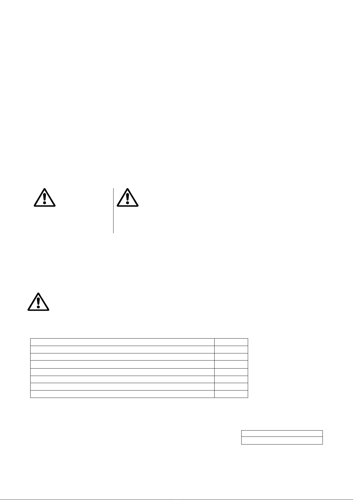
2. PUMPABLE LIQUIDS
Fresh water
Rainwater
Clear waste water
Dirty water o
Foul waste water containing solid bodies with long fibres o
Fountain water
River or lake water
Max. particle dimension [mm] Ø 5
Suitable
oNot suitable
The pump is watertight and must be immersed in liquid to a maximum depth of 7m. See Table 3.
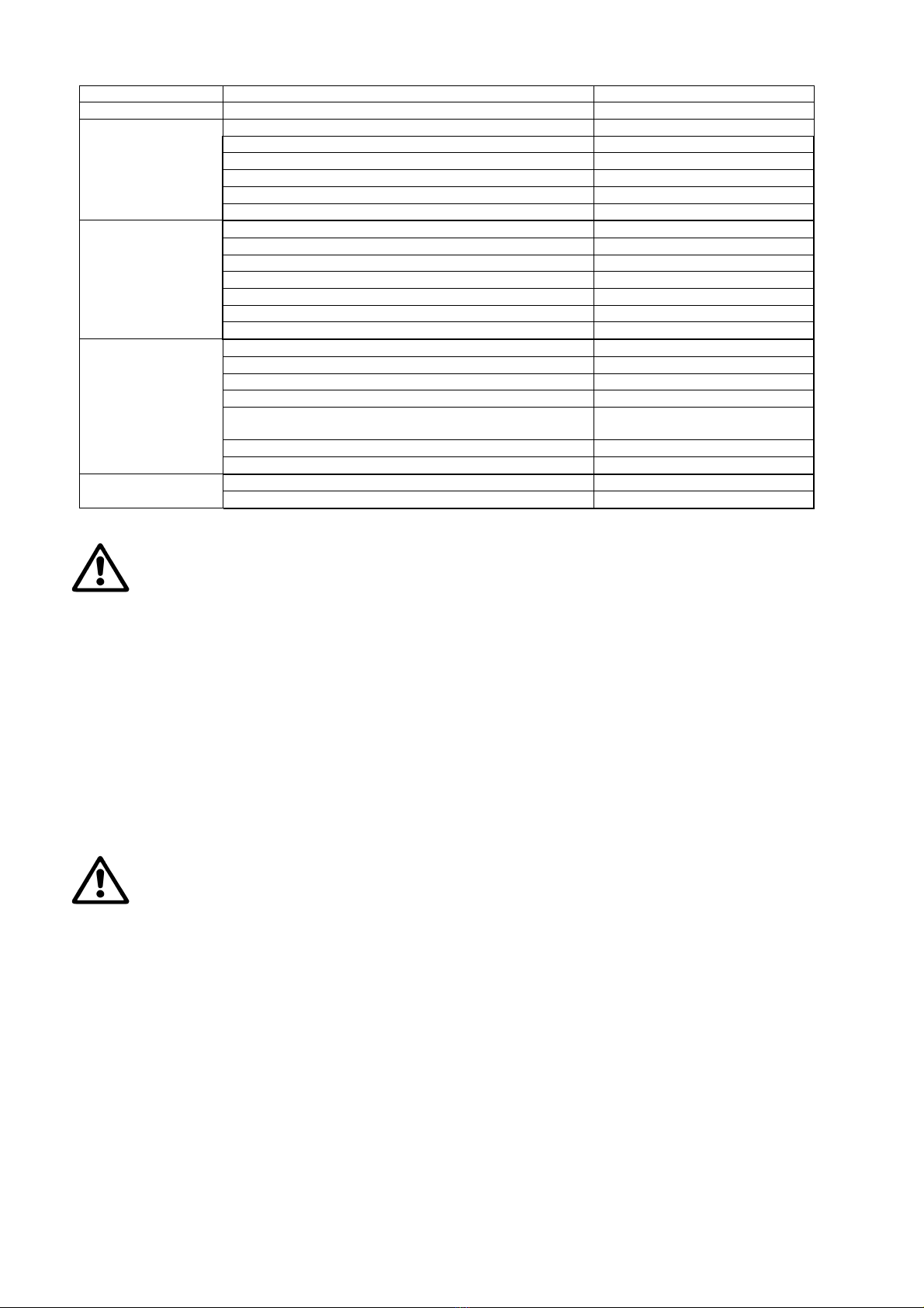
3. TECHNICAL DATA AND LIMITATIONS OF USE
Supply voltage: 230V, see electrical data plate
Delayed line fuses (230V version): indicative values (Ampere)
Storage temperature: -10°C +40°C
Line fuses230V 50Hz
2
Table 1
Table 2

ENGLISH
2
Draining clear water
Model 200
Electrical data P1 Rated absorbed power [W] 220
Mains voltage [V] 1 ~ 230 AC
Mains frequency [Hz] 50
Current [A] 0.9
Capacitor [µF] 4
Capacitor [Vc] 450
Hydraulic data Max. flow rate [l/min] 95
Max. head [m] 5.5
Max. head [bar] 0.55
Max. immersion depth [m] 7
Min. AUT starting height [mm] 220
Min./max. stopping height [mm] 60/110
Residual water height [mm] 2-3
Range of use Length of power cable [m] 10
Type of cable H05 RNF
Grade of motor protection IP X8
Insulation class B
Liquid temperature range [°C]
according to EN 60335-2-41 for domestic
use 0 °C / +35 °C
Max. particle dimension [mm] Ø 5
Max. ambient temperature [°C] +40 °C
Weight DNM GAS 1'' 1/4 F
Net/Gross weight approx. [kg] 3.75 / 4.7
The pump which does not stand on a base cannot support the weight of the pipes, which must be
supported in some other way.
4. MANAGEMENT
4.1 Storage
All the pumps must be stored in a dry covered place, with possible constant air humidity, free from vibrations and dust.
They are supplied in their original pack in which they must remain until the time of installation.
4.2
Transport
Avoid subjecting the products to needless impacts and collisions.
4.3 Weight and dimensions
The adhesive plate on the packaging indicates the total weight of the pump and its dimensions.
5. WARNINGS
The pumps must never be carried, lifted or allowed to operate suspended from the power cable; use
the handle provided.
The pump must never be allowed to run when dry.
On the body there is a venting hole to avoid phenomena of cavitation when starting the pump. It is therefore normal
for a small amount of water to come out of the pump during operation. (Fig.1).
The sealing device contains lubricant which is non-toxic but which may alter the characteristics of the water, in the
case of pure water, if the pump were to have any leaks.
6. INSTALLATION
Screw on the elbow with hosetail fitting provided in the packaging. For the clear water version there are two fittings, one
25 mm and one 30 mm; if you want to use a pipe with a larger diameter, change the elbow coupling. Use a pipe
tightening clamp to secure the pipe to the fitting.
If the bottom of the trap where the pump is to be placed is particularly dirty, a raised support should be provided so as
to avoid blocking of the suction grid (Fig.2)
Totally immerse the pump in the water.
Ensure that the minimum dimensions of the trap in which it is housed are as follows:
Min. base dimensions (mm) 460x460 / Min. height (mm) 400
Pay attention to ensure that the float is free to move, leave at least 5 cm from the wall of the trap.
Table 3

ENGLISH
3
The dimensions of the trap must always be in relation to the quantity of water arriving and to the flow of the pump, so
as not to subject the motor to excessive starts/hour; it is strongly recommended not to exceed 20 starts/hour.
The pump must be installed in vertical position!
7. ELECTRICAL CONNECTION
The length of the power cable on the pump limits the maximum depth of immersion in use of the pump.
Follow the indications on the technical data plate and in this manual, table 3.
8. START-UP
There are two operating modes:
MANUAL (A)
Although they have a float, the pumps can be used in manual mode Fig.3
1) Fix the float switch so that it remains vertical above the pump (with the cable below) (a). As long as the float
switch remains raised, the pump keeps operating irrespective of the water level.
2) Insert the plug of the power cable in a 230 V power socket.
3) The pump will start up; ensure that it is immerse in the liquid to be pumped.
Pay attention because the pump will not switch off automatically once it reaches the minimum level; it must be switched
off manually by the user, either by taking the power out of the socket or by lowering the float (automatic operation).
The maximum suction level is reached only during manual operation because, in automatic operating condition, the
automatic float switch stops the pump before it reaches that level.
AUTOMATIC (B)
The models with a float switch are started automatically when the water level rises and will switch off when the required
minimum level is reached (Fig.4).
1) Leave the float free to move.
2) Insert the plug of the power cable in a 230 V power socket.
3) When the float reaches the ON level the pump will start and will continue operating until it reaches the OFF
level.
Regulating the starting/stopping height:
(To know the minimum starting and stopping height, see the Technical Data chapter.)
The cable length must on one hand allow the float switch to move freely and, on the other, prevent it resting on the
bottom. The portion of cable between the float switch and the cable stay notch must not be less than 10 cm long The
shorter the portion of cable between the float switch and the cable stay notch, the lower will be the starting height and the
higher the stopping height. The fixing point can be changed, for example on the lower clip, with the same length, this will
give a lower stopping and starting level (Fig.5). The pump is supplied with a clamp (Fig. 6) that fixes the float cable and
prevents it sliding in the clip; if you decide to lengthen or shorten the free float cable, shift the corresponding clamp if it
cannot be replaced. The single-phase motors are equipped with built-in thermal overload protection and can be
connected directly to the mains. NB: if the motor is overloaded it stops automatically. Once it has cooled it starts again
automatically without requiring any manual intervention.
9. PRECAUTIONS
RISK OF FROST: when the pump remains inactive at a temperature lower than 0°C, it is necessary to ensure that there
is no water residue which could freeze, causing cracks in the plastic parts.
If the pump has been used with substances that tend to form a deposit, or with water containing chlorine, rinse it after
use with a powerful jet of water in order to avoid the formation of deposits or encrustations which would reduce the
characteristics of the pump.
10. MAINTENANCE AND CLEANING
In normal operation the pump does not require any type of maintenance. In any case, all repair and maintenance work
must be carried out only after having disconnected the pump from the supply mains. When restarting the pump, ensure
that the suction filter is always fitted so as not to create the risk or possibility of accidental contact with moving parts.

ENGLISH
4
10.1 Cleaning the suction grid
(Fig.7)
Switch off the electric power supply to the pump.
Drain the pump.
Unscrew the retaining screws on the filter (b).
Remove the suction grid (c)
Clean and reassemble the suction grid.
10.2 Cleaning the impeller
(Fig.8)
Switch off the electric power supply to the pump.
Drain the pump.
Unscrew the retaining screws on the filter (b).
Remove the suction grid (c)
Wash the pump with clean water to remove possible
impurities between the motor and the pump jacket.
(d).
Clean the impeller (d).
Check that the impeller can turn freely.
Assemble the parts, proceeding in inverse order to
disassembly.
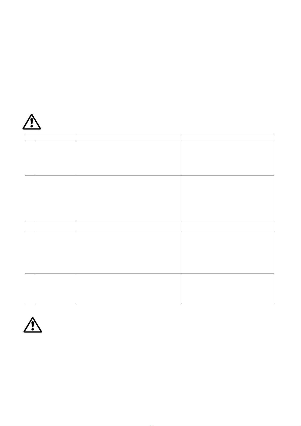
11. TROUBLESHOOTING
Before taking any troubleshooting action, disconnect the pump from the power supply (i.e. remove the
plug from the socket). If there is any damage to the power cable or pump, any necessary repairs or
replacements must be performed by the manufacturer or his authorized customer support service, or
by an equally-qualified party, in order to prevent all risks.
FAULTS CHECKS (possible causes) REMEDIES
1 The motor
does not start
and does not
make any
noise.
A. Check that voltage is reaching the moto
r
.
B. Check the protection fuses.
C. The switch is not activated by the float.
A. Check that the plug is inserted
correctly.
B. If burnt out, change them.
-If burnt out, change them. Place it facing
up.
- Increase the depth of the trap.
2
The pump does
not deliver flow A. The suction grid or the pipes are blocked.
B. The impeller is worn or blocked.
C. The head required is higher than the pump’s
characteristics.
D. Presence of air
A. Remove the obstructions or straighten
the hose if it is twisted.
B. Replace the impeller or remove the
obstruction.
C. Replace it with one with a higher head.
D. Wait at least 1 minute until it is
eliminated
3 The pump does
not stop.
A. The switch is not deactivated by the float A. Check that the float can move freely.
4 The flow rate is
insufficient
A. Check that the suction grid is not partially
blocked
B. Check that the impeller or the delivery pipe
are not partly blocked or encrusted.
C. Ensure that the check valve (if contemplated)
is not partially blocked
A. Remove any obstructions.
B. Remove any obstructions.
C. Accurately clean the check valve
5 The pump stops
after having run
for a short time.
A. The thermal overload protection device stops
the pump.
A. Check that the fluid to be pumped is not
too dense as it would cause overheating
of the motor.
B. Check that the water temperature is not
too high.
12. GUARANTEE
Any modification made without prior authorisation relieves the manufacturer of all responsibility. All the
spare parts used in repairs must be authentic and all accessories must be authorised by the
manufacturer, in order to ensure maximum safety of the machines and of the systems in which they may
be installed.
This product is covered by a legal guarantee (in the European Community for 24 months from date of purchase) against
all defects that can be assigned to manufacturing faults or to the material used.
The product under guarantee may, at discretion, either be replaced with one in perfect working order or replaced free of
charge if the following conditions are observed:
the product has been used correctly in compliance with the instructions and not attempt has been made to
repair it by the buyer or by third parties.
the product has been consigned to the outlet where it was purchased, attaching a document as proof of
purchase (invoice or cash register receipt) and a brief description of the problem found.
The impeller and parts subject to wear are not covered by the guarantee. Intervention under guarantee does not extend
the initial guarantee period in any way.

ITALIANO
5
INDICE
1. APPLICAZIONI ............................................................................................................................................ 5
2. LIQUIDI POMPABILI.................................................................................................................................... 5
3. DATI TECNICI E LIMITAZIONI D’USO ....................................................................................................... 5
4. GESTIONE................................................................................................................................................... 6
4.1Immagazzinaggio................................................................................................................................ 6
4.2
T
rasporto............................................................................................................................................. 6
4.3Peso e dimensioni............................................................................................................................... 6
5. AVVERTENZE.............................................................................................................................................. 6
6. INSTALLAZIONE......................................................................................................................................... 6
7. ALLACCIAMENTO ELETTRICO................................................................................................................. 7
8. AVVIAMENTO.............................................................................................................................................. 7
9. PRECAUZIONI............................................................................................................................................. 7
10. MANUTENZIONE E PULIZIA.................................................................................................................... 7
10.1 Pulizia della griglia di aspirazione ........................................................................................................ 8
10.2 Pulizia della girante .............................................................................................................................. 8
11. RICERCA GUASTI..................................................................................................................................... 8
12. GARANZIA................................................................................................................................................. 8
AVVERTENZE
Prima di procedere
all’installazione leggere
attentamente tutta la
documentazione.
Non toccare mai l’acqua quando la pompa ha la spina inserita, anche
se non sta funzionando. Prima di ogni intervento staccare la spina. Evitare nel
modo più assoluto il funzionamento a secco: la pompa va azionata
esclusivamente quando è immersa nell’acqua. Se questa si esaurisce, la
pompa deve essere subito disattivata staccando la spina dalla corrente.
1. APPLICAZIONI
Le pompe sono di tipo sommergibile, progettate e costruite per pompare acque chiare, per impieghi domestici, con
funzionamento manuale o automatico, per prosciugamento di scantinati ed autorimesse soggette ad allagamenti, per
pompaggio di pozzi di drenaggio, pompaggio di pozzetti raccolta acque piovane o di infiltrazioni provenienti da grondaie,
etc.
Grazie alla forma compatta e maneggevole trovano anche particolari applicazioni come pompe portatili per casi di
emergenza quali, prelievo d‘acqua da serbatoi o fiumi, svuotamento di piscine e fontane o di scavi o sottopassaggi.
Idonea anche per giardinaggio ed hobbistica in genere.
Queste pompe non possono essere utilizzate in piscine, stagni, bacini con presenza di persone, e o
per il pompaggio di idrocarburi (benzina, gasolio, oli combustibili, solventi, ecc.) secondo le norme
antinfortunistiche vigenti in materia. Non sono progettate per un uso continuo, ma di emergenza per
un periodo limitato. Prima di riporle sarebbe buona norma prevedere una fase di pulizia. Vedi capitolo
“Manutenzione e Pulizia”.
2. LIQUIDI POMPABILI
Acque fresche
Acqua piovana
Acque chiare di rifiuto
Acque sporche o
Acque cariche grezze contenenti corpi solidi con fibre lunghe o
Acqua di fontana
Acqua di fiume o lago
Dimensione delle particelle max. [mm] Ø 5
Adatto
oNon adatto
La pompa e’ a tenuta stagna e deve essere immersa nel liquido fino ad una profondita’ massima di 7m. Vedi Tabella 3.
3. DATI TECNICI E LIMITAZIONI D’USO
Tensione di alimentazione: 230V, vedi targhetta dati elettrici
Fusibili di linea ritardati (versione 230V): valori indicativi
(Ampere)
Temperatura di magazzinaggio: -10°C +40°C
Fusibili di linea 230V 50Hz
2
Tabella1
Tabella 2

ITALIANO
6
Drenaggio acque
chiare
Modello 200
Dati Elettrici P1 Potenza assorbita Nominale [W] 220
Voltaggio di rete [V] 1 ~ 230 AC
Frequenza di rete [Hz] 50
Corrente [A] 0.9
Condensatore [µF] 4
Condensatore [Vc] 450
Dati Idraulici Portata max. [l/min] 95
Prevalenza max. [m] 5.5
Prevalenza max. [bar] 0.55
Max. profondita' immersione [m] 7
Altezza di avvio min. AUT [mm] 220
Altezza di arresto min./max. [mm] 60/110
Altezza acqua residua [mm] 2-3
Campo d'impiego Lungh. Cavo alimentazione [m] 10
Tipo cavo H05 RNF
Grado di protezione del motore IP X8
Classe d'isolamento B
Campo temperatura del liquido [°C]
secondo EN 60335-2-41 per uso domestico 0 °C / +35 °C
Dimensione delle particelle max. [mm] Ø 5
Max. Temperatura ambiente [°C] +40 °C
Peso DNM GAS 1'' 1/4 F
Peso Netto/Lordo ca. [kg] 3.75 / 4.7
Tabella 3
La pompa che non appoggia su una base non può sorreggere il peso delle tubazioni il quale
dev’essere sostenuto diversamente.
4. GESTIONE
4.1 Immagazzinaggio
Tutte le pompe devono essere immagazzinate in luogo coperto, asciutto e con umidità dell’aria possibilmente costante,
privo di vibrazioni e polveri. Vengono fornite nel loro imballo originale nel quale devono rimanere fino al momento
dell’installazione.
4.2
T
rasporto
Evitare di sottoporre i prodotti ad inutili urti e collisioni.
4.3 Peso e dimensioni
La targhetta adesiva posta sull’imballo riporta l’indicazione del peso totale dell’elettropompa e delle sue dimensioni.
5. AVVERTENZE
Le pompe non devono mai essere trasportate, sollevate o fatte funzionare sospese facendo uso del
cavo di alimentazione, utilizzare l’apposita maniglia.
La pompa non deve mai essere fatta funzionare a secco.
Sul corpo è previsto un foro di sfiato per evitare fenomeni di cavitazione al momento dell’avvio della pompa.
Durante il funzionamento della pompa è quindi normale una piccola fuoriuscita d’acqua attraverso lo stesso
(Fig.1).
Il dispositivo di tenuta contiene del lubrificante atossico ma che può alterare le caratteristiche dell’acqua, nel caso si
tratti di acqua pura, se la pompa dovesse avere delle perdite.
6. INSTALLAZIONE
Avvitare il gomito con attacco portagomma presente nell’imballo. Per la versione acque chiare si hanno a disposizione
due attacchi uno da 25 mm e uno da 30mm, nel caso di si volesse utilizzare una tubazione con diametro superiore
sostituire il raccordo a gomito. Utilizzare inoltre una fascetta stringitubo per fissare il tubo all’attacco.
Nel caso in cui il fondo del pozzetto, dove la pompa dovrà poggiare, presentasse notevole sporcizia, è opportuno
prevedere un supporto rialzato al fine di evitare intasamenti alla griglia di aspirazione (Fig.2).
Immergere totalmente la pompa nell’acqua.
Prevedere che il pozzetto di alloggiamento abbia dimensioni minime come valori seguenti:
Dimensioni base min. (mm) 460x460 / Altezza min. (mm) 400

ITALIANO
7
Fare attenzione affinche’ il galleggiante sia libero di muoversi, lasciare almeno 5 cm dalla parete del pozzetto.
Il pozzetto dovrà sempre essere dimensionato anche in relazione alla quantità d’acqua in arrivo ed alla portata della
pompa in modo da non sottoporre il motore ad eccessivi avviamenti/ora, e’ strettamente consigliato non superare i 20
avviamenti/ora.
La pompa deve essere installata in posizione verticale!
7. ALLACCIAMENTO ELETTRICO
La lunghezza del cavo di alimentazione presente sulla pompa limita la profondità massima di
immersione nell’utilizzo della pompa stessa. Attenersi alle indicazioni riportate in targhetta tecnica e in
questo manuale tabella 3.
8. AVVIAMENTO
Esistono due modalita’ di funzionamento:
MANUALE (A)
Le elettropompe pur avendo il galleggiante possono essere usate in modalita’ manuale Fig.3
1) Fissare l’interruttore flottante in modo che rimanga verticale sopra la pompa (con il cavo in basso) (a).Fino a
quando l’interruttore flottante resta sollevato, la pompa rimane in funzione indipendentemente dal livello
dell’acqua.
2) Inserire la spina del cavo di alimentazione in una presa di corrente a 230 V.
3) La pompa entrera’ in funzione, assicurarsi che sia immersa nel liquido da aspirare.
Prestare attenzione in quanto la pompa non si spegnera’ in automatico, una volta raggiunto il livello minimo dovra’
essere spenta manualmente dall’utente, o disinserendo la spina oppure abbassando il galleggiante (funzionamento
automatico).
Il livello di aspirazione massimo viene raggiunto solo durante il funzionamento in manuale poiché nella condizione di
funzionamento automatico l’interruttore flottante arresta la pompa prima del raggiungimento di tale livello.
AUTOMATICA (B)
I modelli provvisti d’interruttore a galleggiante vengono messi in funzione automaticamente quando il livello dell’acqua
sale e si spegneranno al raggiungimento del livello minimo previsto (Fig.4).
1) Lasciare libero il galleggiante di muoversi.
2) Inserire la spina del cavo di alimentazione in una presa di corrente a 230 V.
3) Quando il galleggiante raggiunge il livello ON la pompa si avviera’ e rimarra’ in funzione fino al raggiungimento
del livello di OFF.
Regolazione dell’altezza di avvio/arresto:
(Per conoscere l'altezza di inserimento e disinserimento minima, consultare il capitolo Dati tecnici.)
La lunghezza del cavo deve da una parte consentire all’interruttore flottante di potersi muovere liberamente e dall’altra
evitare che lo stesso poggi sul fondo. La porzione di cavo fra l’interruttore flottante e l’incavo fermacavo non deve
misurare meno di 10 cm. Tanto più corta è la porzione di cavo fra l’interruttore flottante e l’incavo fermacavo, tanto più
bassa sarà l’altezza di avvio e tanto più alta quella di arresto. Si puo’ cambiare punto di fissaggio, ad esempio sulla clip
inferiore, a parita’ di lunghezza, si avra’ un livello piu’ basso di arresto e di partenza (Fig.5). La pompa viene fornita con
una fascetta (Fig. 6) che fissa il cavo del galleggiante e ne impedisce lo scorrimento nella clip, nel caso si decidesse di
allungare o accorciare il cavo libero del galleggiante spostare la fascetta in corrispondenza, se non fosse possibile
prevederne la sostituzione. I motori monofase sono muniti di protezione termo-amperometrica incorporata e possono
essere collegati direttamente alla rete. NB: se il motore è sovraccarico si ferma automaticamente. Una volta raffreddato
riparte automaticamente senza bisogno di alcun intervento manuale.
9. PRECAUZIONI
PERICOLO DI GELO: quando la pompa rimane inattiva a temperatura inferiore a 0°C, è necessario assicurarsi che
non ci siano residui d’acqua che ghiacciando possano creare incrinature delle parti plastiche.
Se la pompa è stata utilizzata con sostanze che tendono a depositarsi, o con acqua clorata risciacquare dopo l ‘uso,
con un potente getto d’acqua in modo da evitare il formarsi di depositi od incrostazioni che tenderebbero a ridurre
le caratteristiche della pompa.
10. MANUTENZIONE E PULIZIA
L’elettropompa nel funzionamento normale non richiede alcun tipo di manutenzione. In ogni caso tutti gli interventi di
riparazione e manutenzione si devono effettuare solo dopo aver scollegato la pompa dalla rete di alimentazione. Quando
si fa ripartire la pompa, assicurarsi che sia sempre montato il filtro di aspirazione in modo da non creare pericolo o
possibilità di contatto casuale con le parti in movimento.

ITALIANO
8
10.1 Pulizia della griglia di aspirazione
(Fig.7)
Disinserire l’alimentazione elettrica della pompa.
Far drenare la pompa
Svitare le viti di fissaggio sul filtro (b).
Rimuovere la griglia di aspirazione (c)
Pulire e rimontare la griglia di aspirazione.
10.2 Pulizia della girante
(Fig.8)
Disinserire l’alimentazione elettrica della pompa.
Far drenare la pompa
Svitare le viti di fissaggio sul filtro (b).
Rimuovere la griglia di aspirazione (c)
Lavare la pompa con acqua pulita per rimuovere
possibili impurità fra il motore e la camicia della
pompa (d).
Pulire la girante (d).
Verificare che la girante possa ruotare liberamente.
Assemblare le parti in senso opposto alla sequenza di
smontaggio
11. RICERCA GUASTI
Prima di iniziare la ricerca guasti è necessario interrompere il collegamento elettrico della pompa (togliere la spina
dalla presa). Se il cavo di alimentazione o la pompa in qualsiasi sua parte elettrica è danneggiata l’intervento di
riparazione o sostituzione deve essere eseguito dal Costruttore o dal suo servizio di assistenza tecnica o da una
persona con qualifica equivalente in modo da prevenire ogni rischio.
INCONVENIENTI
V
ERIFICHE (possibili cause) RIMEDI
1 Il motore non
parte e non
genera rumori
A. Verificare che il motore sia sotto tensione.
B. Verificare i fusibili di protezione.
C. L’interruttore non viene attivato dal
galleggiante
A. Verificare che la spina sia
correttamente inserita
B. Se bruciati sostituirli
C. -Verificare che il galleggiante si muova
liberamente.Porlo verso l’alto.
- Aumentare la profondità del pozzetto
2 La pompa non
eroga portata A. La griglia di aspirazione o le tubazioni sono
ostruite.
B. La girante è usurata od ostruita.
C. La prevalenza richiesta è superiore alle
caratteristiche della pompa
D. Presenza d’aria
A. Rimuovere le ostruzioni o distendere la
tubazione se attorcigliata.
B. Sostituire la girante o rimuovere
l’ostruzione.
C. Sostituirla con una con prevalenza piu’
alta.
D. Attendere almeno 1 minuto finche’ non
viene eliminate.
3 La pompa non si
arresta A. L’interruttore non viene disattivato dal
galleggiante. A. Verificare che il galleggiante si muova
liberamente
4 La portata è
insufficiente A. Verificare che la griglia di aspirazione non sia
parzialmente ostruita.
B. Verificare che la girante o il tubo di mandata
non siano parzialmente ostruiti od incrostati.
C. Verificare che la valvola di ritegno (se
prevista) non sia parzialmente intasata
A. Rimuovere eventuali ostruzioni.
B. Rimuovere eventuali ostruzioni.
C. Pulire accuratamente la valvola di
ritegno
5 La pompa si
arresta dopo aver
funzionato poco
tempo.
A. Il dispositivo di protezione termo
amperometrica arresta la pompa
A. Verificare che il liquido da pompare
non sia troppo denso perché
causerebbe il surriscaldamento del
motore.
B. Verificare che la temperatura
dell’acqua non sia troppo elevata
12. GARANZIA
Qualsiasi modifica non autorizzata preventivamente, solleva il costruttore da ogni tipo di responsabilità.
Tutti i pezzi di ricambio utilizzati nelle riparazioni devono essere originali e tutti gli accessori devono
essere autorizzati dal costruttore, in modo da poter garantire la massima sicurezza delle macchine e degli
impianti su cui queste possono essere montate.
Questo prodotto è coperto da garanzia legale (nella Comunità Europea per 24 mesi a partire dalla data di acquisto)
relativamente a tutti i difetti imputabili a vizi di fabbricazione o di materiale impiegato.
Il prodotto in garanzia potrà essere, a discrezione, o sostituito con uno in perfetto stato di funzionamento o riparato
gratuitamente qualora vengano osservate le seguenti condizioni:
il prodotto sia stato adoperato in modo corretto e conforme alle istruzioni e nessun tentativo di riparazione sia
stato eseguito dall'acquirente o da terzi,
il prodotto sia stato consegnato nel punto vendita di acquisto, allegando il documento che attesta l'acquisto
(fattura o scontrino fiscale) e una breve descrizione del problema riscontrato.
La girante e le parti soggette a usura, non rientrano nella garanzia. L'intervento in garanzia non estende in nessun caso
il periodo iniziale.

DEUTSCH
9
INHALT
1. ANWENDUNGEN......................................................................................................................................... 9
2. PUMPBARE FLÜSSIGKEITEN ................................................................................................................... 9
3. TECHNISCHE DATEN UND EINSATZBESCHRÄNKUNGEN ................................................................... 9
4. UMGANG ................................................................................................................................................... 10
4.1Einlagerung....................................................................................................................................... 10
4.2Transport........................................................................................................................................... 10
4.3Gewicht und Abmessungen.............................................................................................................. 10
5. HINWEISE.................................................................................................................................................. 10
6. INSTALLATION ......................................................................................................................................... 10
7. ELEKTROANSCHLUSS............................................................................................................................ 11
8. EINSCHALTEN.......................................................................................................................................... 11
9. VORSICHTSMASSNAHMEN .................................................................................................................... 11
10. WARTUNG UND REINIGUNG................................................................................................................. 11
10.1 Reinigung des Ansauggitters ............................................................................................................. 12
10.2 Reinigung des Laufrads ..................................................................................................................... 12
11. STÖRUNGSSUCHE................................................................................................................................. 12
12. GARANTIE............................................................................................................................................... 12
HINWEISE
Vor dem Einbau die
ganzen Unterlagen
aufmerksam lesen.
Nie das Wasser berühren, wenn die Pumpe eingesteckt ist, auch
wenn sie nicht in Betrieb ist. Vor jedem Eingriff den Stecker abziehen. Auf
jeden Fall einen Trockenbetrieb vermeiden. Die Pumpe darf nur in Wasser
eingetaucht in Betrieb genommen werden. Wenn kein Wasser mehr vorhanden
ist, muss die Pumpe sofort ausgeschaltet werden, indem der Stecker aus der
Steckdose gezogen wird.
1. ANWENDUNGEN
Bei diesen Pumpen handelt es sich um Tauchpumpen, die für das Pumpen von klarem Wasser im Haushalt bestimmt
sind, mit Hand- und Automatikbetrieb, für das Trocknen von Überschwemmungen ausgesetzten Kellern oder Garagen,
für das Pumpen von Drainageschächten, Regenwasser oder Einsickerungen aus Regenrinnen usw.
Dank der kompakten, handlichen Form werden sie auch als mobile Pumpen in Notfällen eingesetzt, wie zur Entnahme
von Wasser aus Tanks oder Flüssen, Leeren von Wasserbecken und Brunnen, Entwässerung von Gruben oder
Unterführungen. Außerdem können sie im Garten und für Hobby-Anwendungen eingesetzt werden.
Gemäß der einschlägigen Unfallschutzvorschriften dürfen diese Pumpen nicht in von Personen
besetzten Schwimmbecken, Teichen, Wasserbecken oder zum Pumpen von Kohlenwasserstoffen
(Benzin, Gasölen, Heizö-len, Lösemitteln, usw.) eingesetzt werden. Sie sind nicht für einen
durchgehenden Einsatz, sondern für Notfälle und eingeschränkte Zeiträume entwickelt worden. Bevor
sie wieder gelagert werden, sollten sie gereinigt werden. Siehe Kapitel „Wartung und Reinigung“.
2. PUMPBARE FLÜSSIGKEITEN
Frischwasser
Regenwasser
Klares Abwasser
Schmutzwasser o
Belastetes Rohwasser mit langfaserigen Festkörpern o
Brunnenwasser
Wasser aus Flüsse und Seen
Max. Abmessung der Partikel [mm] Ø 5
Geeignet
oUngeeignet
Die Pumpe ist dicht und muss in die Flüssigkeit bis zu einer max. Tiefe von 7 m eingetaucht werden. Siehe Tabelle 3.
3. TECHNISCHE DATEN UND EINSATZBESCHRÄNKUNGEN
Versorgungsspannung: 230V, siehe Schild der
elektrischen Daten
Träge Leitungssicherungen (Version 230v): hinweisende
Werte (Ampere)
Lagertemperatur: -10°C +40°C
Leitungssicherungen
230V 50Hz
2
Tabelle 1
Tabelle 2
DEUTSCH
10
Drainage von klarem Wasser
Modell 200
Elektrische Daten P1 Aufgenommene Nennleistung (W) 220
Netzspannung (V) 1 ~ 230 AC
Netzfrequenz (Hz) 50
Strom (A) 0.9
Kondensator [µF] 4
Kondensator [Vc] 450
Hydraulikdaten Höchstförderleistung [l/min] 95
Höchstförderhöhe [m] 5.5
Höchstförderhöhe [bar] 0.55
Max. Tauchtiefe (m) 7
Mindestarthöhe AUT [mm] 220
Mind./max. Stopphöhe [mm] 60/110
Höhe Restwasser (mm) 2-3
Anwendungsbereich Länge Stromkabel (m) 10
Kabeltyp H05 RNF
Schutzart des Motors IP X8
Isolierungsklasse B
Flüssigkeitstemperaturbereich [°C] nach EN 60335-2-41
für Hausgebrauch 0 °C / +35 °C
Max. Abmessung der Partikel [mm] Ø 5
max. Umgebungstemperatur (°C) +40 °C
Gewicht DNM GAS 1'' 1/4 F
Netto-/Bruttogewicht ca. [kg] 3.75 / 4.7
Tabelle 3
Wenn die Pumpe nicht zuverlässig gestützt wird, ist sie nicht in der Lage, das Gewicht der Rohre zu
tragen, die in diesem Fall separat gesichert werden müssen.
4. UMGANG
4.1 Einlagerung
Alle Pumpen müssen an einem überdachten, trockenen, staubund vibrationsfreien Ort mit möglichst konstanter
Luftfeuchtigkeit gelagert werden. Sie werden in ihrer Originalverpackung geliefert, in der sie bis zum Augenblick der
Installation verbleiben müssen.
4.2 Transport
Unnötige Schlageinwirkungen und Kollisionen vermeiden.
4.3 Gewicht und Abmessungen
Das Etikett an der Verpackung führt die Angabe des Gesamtgewichts der Elektropumpe und ihre Abmessungen auf.
5. HINWEISE
Die Pumpen dürfen nie mithilfe des Stromkabels transportiert, angehoben oder in Betrieb genommen
werden - hierfür muss der vorhandene Griff verwendet werden.
Die Pumpe darf niemals trocken laufen.
Am Körper der Pumpe befindet sich eine Entlüftungsöffnung, dank der Kavitationsphänomene während dem
Anlaufen der Pumpe vermieden werden. Es ist folglich normal, wenn während der normalen Funktion der Pumpe
etwas Wasser aus dieser Öffnung austritt. (Abb. 1).
Die Dichtung enthält Schmiermittel, das zwar ungiftig ist, aber trotzdem die Merkmale von reinem Wasser verändern
kann, wenn die Pumpe leckt.
6. INSTALLATION
Den Winkel mit dem in der Verpackung vorhandenen Schlauchhalteranschluss einschrauben. Für die Ausführung für
Klarwasser stehen zwei Anschlüsse zur Verfügung, ein 25 mm und ein 30 mm - Anschluss, falls eine Leitung mit einem
höheren Durchmesser verwendet wird, den Winkelanschluss ersetzen. Außerdem eine Rohrschelle verwenden, um das
Rohr dem Anschluss zu befestigen.
Falls der Boden des Schachts, wo die Pumpe aufliegt, stark verschmutzt sein sollte, sollte eine höhere Halterung
vorgesehen werden, um Verstopfungen des Ansauggitters zu vermeiden (Abb. 2).
Die Pumpe ganz in das Wasser tauchen
Vorsehen, dass der Aufnahmeschacht die folgenden Mindestabmessungen aufweist:
Mindestgrundabmessungen (mm) 460x460 / Mindesthöhe (mm) 400.

DEUTSCH
11
Darauf achten, dass der Schwimmer sich frei bewegen kann, mindestens 5 cm von der Schachtwand Abstand halten.
Der Schacht muss aufgrund der eintretenden Wassermenge und der Fördermenge der Pumpe bemessen sein, damit
der Motor keinen zu hohen Starts/Stunde ausgesetzt wird; es ist sehr empfehlenswert, 20 Starts/Stunde nicht zu
überschreiten.
Die Pumpe muss senkrecht installiert werden!
7. ELEKTROANSCHLUSS
Die Länge des Kabels an der Pumpe begrenzt die max. Tauchtiefe beim Einsatz der Pumpe selbst. Sich an
die Angaben auf dem Typenschild und der hier aufgeführten Tabelle 3 halten.
8. EINSCHALTEN
Es gibt zwei Betriebsweisen:
VON HAND (A)
Die Elektropumpen haben zwar einen Schwimmer, können aber von Hand verwendet werden - Abb. 3
1) Den Schwimmerschalter so befestigen, dass er vertikal über der Pumpe verbleibt (mit dem Kabel nach unten)
(a). Solange der Schwimmerschalter angehoben bleibt, bleibt die Pumpe unabhängig von der Wasserhöhe in
Betrieb.
2) Den Stecker des Stromkabels in eine 230 V - Steckdose stecken.
3) Die Pumpe tritt in Funktion - sicherstellen, dass sie in der anzusaugenden Flüssigkeit eingetaucht ist.
Aufpassen - da die Pumpe nicht automatisch abgestellt wird; wenn die Mindesthöhe erreicht wird, muss sie vom
Anwender von Hand ausgeschaltet, der Stecker abgezogen oder der Schwimmer gesenkt werden (Automatikbetrieb).
Das Höchstansaugniveau wird nur in der manuellen Betriebsweise erreicht, da im Automatikbetrieb der
Schwimmerschalter die Pumpe vor dem Erreichen dieser Höhe stoppt.
AUTOMATISCH (B)
Die mit einem Schwimmerschalter ausgestatteten Modelle werden automatisch in Betrieb gesetzt, wenn die Wasserhöhe
steigt; sie werden bei Erreichen der vorgesehen Mindesthöhe ausgeschaltet (Abb. 4).
1) Dem Schwimmer ermöglichen, sich frei zu bewegen
2) Den Stecker des Stromkabels in eine 230 V - Steckdose stecken.
3) Wenn der Schwimmer das Niveau ON erreicht, startet die Pumpe und bleibt bis Erreichen des Niveaus OFF in
Betrieb.
Einstellung der Start-/Stopphöhe:
(Um die Mindesteinschalt- und -ausschalthöhe zu kennen, das Kapitel Technische Daten einsehen).
Die Kabellänge muss auf der einen Seite dem Schwimmerschalter ermöglichen, sich frei zu bewegen, und auf der
anderen vermeiden, dass dieser am Boden aufliegt. Die Kabelportion zwischen Schwimmerschalter und
Kabelhalterkerbe darf nicht weniger als 10 cm betragen. Je kürzer die Kabelportion zwischen Schwimmerschalter und
Kabelhalterkerbe ist, umso niedriger ist die Starthöhe und umso höher ist die Stopphöhe. Man kann den
Befestigungspunkt ändern, z.B. am unteren Clip; bei gleicher Länge erhält man eine niedrigere Stopp- und Starthöhe
(Abb. 5). Die Pumpe wird mit einer Schelle (Abb. 6) geliefert, die das Kabel des Schwimmers befestigt und das Gleiten
im Clip verhindert: Wenn man entscheidet, das freie Kabel des Schwimmers zu verlängern oder zu kürzen, wird die
Schelle je nach Fall versetzt, falls dies nicht möglich ist, den Ersatz vornehmen. Die einphasigen Motoren weisen einen
integrierten Thermo-Amperemeter-Schutz auf können direkt ans Netz geschlossen werden. HINWEIS: Wenn der Motor
überlastet ist, hält er automatisch an. Wenn er abgekühlt ist, startet er automatisch, ohne von Hand eingreifen zu
müssen.
9. VORSICHTSMASSNAHMEN
FROSTGEFAHR Wenn die Pumpe bei einer Temperatur unter 0°C außer Betrieb bleibt, sicherstellen, dass keine
Wasserreste verbleiben, die vereisen und die Kunststoffteile beschädigen könnten.
Wenn die Pumpe mit Substanzen verwendet wurde, die sich ablagern, oder mit Chlorwasser, nach dem Gebrauch mit
Wasser gut abspritzen, damit keine Ablagerungen oder Verkrustungen entstehen, die die Eigenschaften der Pumpe
einschränken würden.
10. WARTUNG UND REINIGUNG
Bei normalem Betrieb erfordert die Pumpe keinerlei Wartung. In jedem Fall dürfen alle Reparatur- und Wartungsarbeiten
ausschließlich bei spannungslos gemachter Pumpe durchgeführt werden. Bevor die Pumpe wieder eingeschaltet wird,
stets kontrollieren, ob der Ansaugfilter wieder eingebaut wurde, damit jedes Risiko der zufälligen Berührung von
Bewegungsteilen ausgeschlossen wird.
DEUTSCH
12
10.1 Reinigung des Ansauggitters
(Abb. 7)
Die Spannungsversorgung der Pumpe
unterbrechen.
Die Pumpe entleeren
Die Befestigungsschrauben am Filter (b)
abschrauben.
Das Ansauggitter ausbauen (c)
Das Ansauggitter säubern und wieder einbauen.
10.2 Reinigung des Laufrads
(Abb. 8)
Die Spannungsversorgung der Pumpe unterbrechen.
Die Pumpe entleeren
Die Befestigungsschrauben am Filter (b)
abschrauben.
Das Ansauggitter ausbauen (c)
Die Pumpe mit sauberem Wasser waschen, damit
mögliche Verschmutzungen zwischen Motor und
Pumpenmantel beseitigt werden. (d).
Das Laufrad reinigen (d).
Kontrollieren, ob das Laufrad frei drehen kann.
Die Teile in umgekehrter Reihenfolge wieder
zusammenbauen.
11. STÖRUNGSSUCHE
Vor der Fehlersuche muss die Pumpe vom Stromnetz getrennt werden (Netzstecker ziehen).
Wenn Netzkabel oder elektrische Teile der Pumpe beschädigt sind, müssen die Reparatur- oder
Ersatzarbeiten zur Unfallverhütung von der Herstellerfirma oder ihrem technischen Kundendienst oder
einer entsprechend qualifizierten Person durchgeführt werden.
STÖRUNGEN KONTROLLEN (mögliche Ursachen)
A
BHILFEN
1 Der Motor läuft
nicht an und
erzeugt keine
Geräusche
A. Kontrollieren, ob der Motorunter Spannung steht.
B. DieSicherungenprüfen.
C. Der Schwimmerschalterschaltet nicht
A. Prüfen, ob der Stecker korrekt
eingesteckt ist.
B. Falls durchgebrannt, ersetzen
-Sicherstellen, dass sich der Schwimmerschalter
freibewegenkann.Nach oben ausrichten.
- Die Schachttiefe vergrößern
2 Die Pumpe gibt
keine Leistung ab. A. Ansauggitter oder Saugleitungen sind
verstopft.
B. Der Propeller ist verschlissen oder verstopft
C. Die geforderte Förderhöhe übersteigt die
Charakteristiken der Pumpe
D. Anwesenheit von Luft.
A. Die Verstopfungen entfernen oder die
eventuell verdrehte Leitung gerade
ziehen.
B. Propeller erset-zen oder Verstopfung
beseitigen.
C. Mit einer Pumpe mit einer höheren
Förderhöhe ersetzen.
D. Mindestens 1 Minute warten, bis sie
beseitigt ist.
3 Die Pumpe hält
nicht an. A. Der Schwimmerschalterschaltet nicht A. Sicherstellen, dass sich der Schwimmerschalter
frei bewegen kann
4 Die Fördemenge
reicht nicht aus. A. Kontrollieren, ob das Ansauggitter teilweise ver-
stopft ist.
B. Kontrollieren, ob der Propeller oder die
Saugleitung teilweise verstopft oder verkrustet
sind.
C. Kontrollieren, ob das Rückschlag-ventil (falls
vor-handen) teilwei-se verstopft ist.
A. Eventuelle Verstopfungen beseitigen.
B. Eventuelle Verstopfungen beseitigen.
C. Das Rückschlagventil gründlich reinigen.
5 Die Pumpe hält
an, nach-dem
sie kurz-fristig
funktio-niert hat.
A. Der Überstromschutz hält die Pumpe an
A. Sicherstellen, dass die zu pumpende
Flüssigkeit nicht zu dickflüssig ist, weil
sonst der Motor überhitzen kann.
Sicherstellen, dass die Temperatur des
Wassers nicht zu hoch ist.
12. GARANTIE
Alle nicht zuvor genehmigten Änderungen entheben den Hersteller von jeder Haftpflicht. Alle für
Reparaturen verwendeten Ersatzteile müssen Originalteile sein und alle Zubehöre müssen vom Hersteller
autorisiert sein, so dass für die Maschinen und Anlagen, an denen diese montiert werden, maximale
Sicherheit gewährleistet werden kann.
Diese Produkt ist von einer gesetzlichen Garantie begleitet (in der Europäischen Gemeinschaft 24 Monate ab dem
Kaufdatum), die alle Mängel aufgrund eines Herstellungsfehlers oder des verwendeten Materials deckt.
Das Produkt unter Garantie kann je nach Fall mit einem perfekt funktionierenden Produkt ersetzt
oder kostenlos repariert werden, wenn die folgenden Bedingungen erfüllt sind:
Das Produkt muss korrekt und den Anleitungen entsprechend verwendet worden sein, es dürfen keine
Reparaturversuche durch den Käufer oder durch Dritte ausgeführt worden sein.
Das Produkt muss in der Verkaufsstelle ausgehändigt und von einem Dokument begleitet werden, das den Kauf
beweist (Rechnung oder Einkaufszettel), und eine kurze Beschreibung des festgestellten Problems aufweisen.
Das Laufrad und die Verschleißteile unterliegen keiner Garantie. Der Garantieeingriff erweitert auf keinen Fall die
Garantiedauer.
FRANÇAIS
13
TABLE DES MATIÈRES
1. Applications.............................................................................................................................................. 13
2. LIQUIDES POMPABLES........................................................................................................................... 13
3. DONNÉES TECHNIQUES ET LIMITES D’UTILISATION......................................................................... 13
4. GESTION.................................................................................................................................................... 14
4.1Stockage ........................................................................................................................................... 14
4.2
Transport
............................................................................................................................................. 14
4.3Poids et dimensions.......................................................................................................................... 14
5. AVERTISSEMENTS................................................................................................................................... 14
6. INSTALLATION ......................................................................................................................................... 14
7. BRANCHEMENT ÉLECTRIQUE ............................................................................................................... 15
8. DÉMARRAGE............................................................................................................................................ 15
9. PRÉCAUTIONS.......................................................................................................................................... 15
10. ENTRETIEN ET LAVAGE........................................................................................................................ 15
10.1 Nettoyage de la crépine d’aspiration.................................................................................................. 16
10.2 Nettoyage de la roue.......................................................................................................................... 16
11. RECHERCHE PANNES........................................................................................................................... 16
12. GARANTIE............................................................................................................................................... 16
AVERTISSEMENTS
Avant de procéder à
l'installation, lire
attentivement toute la
documentation.
Ne jamais toucher l'eau lorsque la fiche de la pompe est insérée,
même si elle ne fonctionne pas. Avant chaque intervention, débrancher la fiche.
Il est strictement interdit de la faire fonctionner à sec : la pompe doit être
actionnée uniquement lorsqu'elle est plongée dans l'eau. Si l'eau s'épuise, la
pompe doit être immédiatement désactivée en débranchant la fiche du courant.
1. APPLICATIONS
Les pompes sont de type submersible, conçues et fabriquées pour pomper de l'eau claire, pour des utilisations
domestiques, avec un fonctionnement manuel ou automatique, pour l'assèchement de sous-sol et de garages sujets aux
inondations, pour le pompage de puits de drainage, le pompage de puits de récolte d'eau de pluie ou d'infiltrations
provenant de gouttières, etc.
Grâce à leur forme compacte et maniable, elles peuvent être utilisées également comme pompes portatives pour les cas
d’urgence comme le puisage d’eau dans des réservoirs ou des rivières, le vidage de piscines et fontaines ou de
tranchées ou passages souterrains. Adaptées également pour le jardinage et le bricolage en général.
Ces pompes ne peuvent pas être utilisées dans des piscines, étangs, bassins en présence de
personnes, ou pour le pompage d’hydrocarbures (essence, gazole, huiles combustibles, solvants, etc.)
conformément aux normes de prévention des accidents en vigueur en la matière. Elles ne sont pas
conçues pour une utilisation continue, mais d'urgence, sur une période limitée. Avant de les ranger, il
faut prévoir une étape de nettoyage. Voir chapitre « Entretien et Nettoyage ».
2. LIQUIDES POMPABLES
Eaux fraîches
Eau de pluie
Eaux usées claires
Eaux usées o
Eaux chargées brutes contenant des corps solides avec des fibres longues o
Eau de fontaine
Eau de rivière ou lac
Dimension max. des particules [mm] Ø 5
Adaptée
oNon adaptée
La pompe est étanche et doit être plongée dans le liquide jusqu'à une profondeur maximale de 7 m. Voir Tableau 3.
3. DONNÉES TECHNIQUES ET LIMITES D’UTILISATION
Tension d’alimentation: 230V voir plaquette des données électriques
Fusibles de ligne retardés (version 230V): valeurs indicatives (Ampères)
Température de stockage : -10°C +40°C
Fusibles de ligne 230V 50Hz
2
Tableau 1
Tableau 2

FRANÇAIS
14
Drainage des eaux
claires
Modèle 200
Données
électriques P1 Puissance absorbée nominale [W] 220
Tension de réseau [V] 1 ~ 230 AC
Fréquence de réseau [Hz] 50
Courant [A] 0.9
Condensateur [µF] 4
Condensateur [Vc] 450
Données
hydrauliques Débit max. [l/min] 95
Hauteur totale nominale max. [m] 5.5
Hauteur totale nominale max. [bar] 0.55
Profondeur max. d'immersion [m] 7
Hauteur de démarrage min. AUT [mm] 220
Hauteur d'arrêt min./max. [mm] 60/110
Hauteur eau résiduelle [mm] 2-3
Champ d'utilisation Long. Câble alimentation [m] 10
Type câble H05 RNF
Degré de protection du moteur IP X8
Classe d'isolation B
Champ température du liquide [°C] selon la
norme EN 60335-2-41 pour usage domestique 0 °C / +35 °C
Dimension max. des particules [mm] Ø 5
Max. Température environnementale [°C] +40 °C
Poids DNM GAZ 1'' 1/4 F
Poids net/Lourd env. [kg] 3.75 / 4.7
Tableau 3
La pompe qui n’est pas en appui sur une base ne peut pas soutenir le poids des tuyaux, celui-ci doit
donc être soutenu d’une autre manière.
4. GESTION
4.1 Stockage
Toutes les pompes doivent être stockées dans un endroit couvert, sec et avec une humidité de l’air si possible
constante, exempt de vibrations et de poussières. Elles sont fournies dans leur emballage d’origine dans lequel elles
doivent rester jusqu’au moment de l’installation.
4.2 Transport
Éviter de soumettre les produits à des chocs et collisions inutiles.
4.3 Poids et dimensions
La plaque adhésive placée sur l'emballage indique le poids total de l'électropompe et ses dimensions.
5. AVERTISSEMENTS
Les pompes ne doivent jamais être transportées, soulevées ou fonctionner suspendues en utilisant le
câble d'alimentation ; utiliser la poignée.
La pompe ne doit jamais fonctionner à sec.
Un purgeur est prévu sur le corps pour éviter les phénomènes de cavitation au moment du démarrage de la pompe.
Durant le fonctionnement de la pompe, il est donc normal de voir sortir un peu d’eau du purgeur. (Fig.1).
Le dispositif d’étanchéité contient du lubrifiant atoxique mais qui peut altérer les caractéristiques de l’eau, quand on
pompe de l’eau pure, si la pompe devait avoir des fuites.
6. INSTALLATION
Serrer le coude avec raccord porte-caoutchouc présent dans l'emballage. Pour la version eau claire, on dispose de deux
raccords, un de 25 mm et un de 30 mm ; pour utiliser une tuyauterie avec un diamètre supérieur, remplacer le raccord en
coude. De plus, utiliser un serre-câble pour fixer le tuyau sur le raccord.
Si le fond du puits, là où doit se poser la pompe, devait présenter de la saleté en quantité importante, prévoir un
support rehaussé pour éviter des engorgements de la crépine d'aspiration (Fig.2).
Plonger entièrement la pompe dans l'eau.
Prévoir que le puits d'emplacement ait des dimensions minimales, selon les valeurs suivantes :

FRANÇAIS
15
Dimensions base min. (mm) 460x460 / Hauteur min. (mm) 400
Faire attention que le flotteur soit libre de se déplacer : laisser au moins 5 cm depuis le mur du puits.
Le puits devrait toujours avoir les dimensions même en relation avec la quantité d'eau en arrivée et au débit de la
pompe, pour ne pas soumettre le moteur et des démarrages excessifs/heure ; il est strictement déconseillé de
dépasser les 20 démarrages/heure.
La pompe doit être installée en position verticale !
7. BRANCHEMENT ÉLECTRIQUE
La longueur du câble d’alimentation présent sur la pompe limite la profondeur maximum d’immersion
pour l’utilisation de celle-ci. Respecter les indications présentes sur la plaque technique et dans le
tableau 3 de ce manuel.
8. DÉMARRAGE
Il existe deux modalités de fonctionnement :
MANUELLE (A)
Les électropompes, tout en ayant le flotteur, peuvent être utilisées en modalité manuelle Fig.3
1) Fixer l'interrupteur flottant pour qu'il reste vertical au-dessus de la pompe (avec le câble en bas) (a).Tant que
l'interrupteur flottant reste soulevé, la pompe fonctionne, indépendamment du niveau de l'eau.
2) Insérer la fiche du câble d'alimentation dans une prise de courant à 230 V.
3) La pompe entrera en fonction: s'assurer qu'elle soit plongée dans le liquide à aspirer.
Prêter une attention toute particulière puisque la pompe ne s'arrêtera pas automatiquement, une fois le niveau minimum
atteint, elle devrait être éteinte manuellement par l'utilisateur, ou en retirant la fiche ou en baissant le flotteur
(fonctionnement automatique).
Le niveau d'aspiration maximum est atteint uniquement pendant le fonctionnement manuel puisque dans la condition de
fonctionnement automatique, l'interrupteur flottant arrête la pompe avant d'atteindre un tel niveau.
AUTOMATIQUE (B)
Les modèles équipés d'un interrupteur à flotteur sont mis en fonction automatiquement lorsque le niveau d'eau monte et
s'arrêtent une fois le niveau minium prévu atteint (Fig.4).
1) Laisser le flotteur libre de se déplacer.
2) Insérer la fiche du câble d'alimentation dans une prise de courant à 230 V.
3) Lorsque le flotteur atteint le niveau ON, la pompe démarrer et reste en fonction jusqu'à atteindre le niveau OFF.
Réglage de la hauteur de démarrage/arrêt:
(pour connaître la hauteur d'activation et de désactivation minimale, consulter le chapitre Données techniques.)
La longueur du câble doit d'un côté autoriser l'interrupteur flottant de pouvoir se déplacer librement et de l'autre, éviter
que celui-ci ne pose sur le fond. La portion de câble entre l'interrupteur flottant et la rainure d'arrêt de câble ne doit pas
mesurer moins de 10 cm. Plus la portion de câble entre l'interrupteur flottant et la rainure d'arrêt de câble est courte, plus
basse sera la hauteur de démarrage et plus élevée sera celle d'arrêt. Il est possible de changer le point de fixation, par
exemple, sur le clip inférieur, pour une même longueur, il faudra un niveau plus bas d'arrêt et de départ (Fig.5). La
pompe est équipée d'une bande (fig. 6) qui fixe le câble du flotteur et en empêche le glissement dans le clip ; s'il fallait
allonger ou raccourcir le câble libre du flotteur, déplacer la bande en correspondance, s'il n'est pas possible d'en prévenir
le remplacement. Les moteurs monophasés sont équipés de protection thermo-ampérométrique incorporée et peuvent
être branchés directement au réseau. NB : si le moteur est surchargé, il s'arrête automatiquement. Une fois refroidi, il
repart automatiquement sans aucune intervention manuelle.
9. PRÉCAUTIONS
Danger de gel : lorsque la pompe reste inactive à température inférieure à 0 °c, il faut s'assurer qu'il n'y ait pas de
résidus d'eau qui en gelant pourraient créer des fêlures de parties en plastique. Si la pompe a été utilisée avec des
substances qui tendent à se déposer, ou avec de l'eau chlorée, rincer après l'utilisation, avec un puissant jet d'eau pour
éviter la formation de dépôts ou d'incrustations qui tendraient à réduire les caractéristiques de la pompe.
10. ENTRETIEN ET LAVAGE
L’électropompe, dans le fonctionnement normal, ne demande aucun type de maintenance. Dans tous les cas, toutes les
interventions de réparation et de maintenance ne doivent être effectuées qu’après avoir débranché la pompe. Quand on
fait repartir la pompe, vérifier que la crépine d’aspiration est toujours montée de manière à ne pas créer de danger ou
possibilité de contact accidentel avec les parties en mouvement.

FRANÇAIS
16
10.1 Nettoyage de la crépine d’aspiration
(Fig.7)
Déconnecter l’alimentation électrique de la
pompe.
Drainer la pompe.
Desserrer les vis de fixation sur le filtre (b).
Enlever la crépine d’aspiration (c)
Nettoyer et remonter la crépine d’aspiration.
10.2 Nettoyage de la roue
(Fig.8)
Déconnecter l’alimentation électrique de la pompe.
Drainer la pompe.
Desserrer les vis de fixation sur le filtre (b).
Enlever la crépine d’aspiration (c)
Laver la pompe avec de l’eau propre pour éliminer les
éventuelles impuretés entre le moteur et la chemise
de la pompe (d).
Nettoyer la roue (d).
Vérifier que la roue peut tourner librement.
Assembler les parties dans le sens contraire à l’ordre
de démontage
11. RECHERCHE PANNES
Avant de commencer la recherche des pannes, il faut interrompre l’alimentation électrique de la pompe
(retirer la fiche de la prise). Si le câble d’alimentation ou un composant électrique quelconque de la
pompe sont abîmés, la réparation ou le remplacement de la pièce doivent être effectués par le
Constructeur ou par son service après-vente, ou bien par une personne ayant une qualification
équivalente de manière à prévenir tout risque.
INCONVÉNIENTS
V
ÉRIFICATIONS (causes possibles) REMÈDES
1 Le moteur ne
démarre pas et
ne fait aucun
bruit.
A. Vérifier que le moteur est sous tension.
B. Vérifier les fusibles de protection
C. L’interrupteur n’est pas activé par leflotteur
A. Vérifier que la fiche soit correctement
insérée
A. S’ils sont grillés, les remplacer.
-Vérifier que le flotteur bouge librement..
Le placer vers le haut
- Augmenter la profondeur du puisard.
2 La pompe n'a
pas de débit A. La crépine d’aspiration ou les tuyaux sont
bouchés.
B. La roue est usée ou bouchée.
C. La hauteur manométrique demandée
dépasse les caractéristiques de la pompe
D. Présence d'air
A. Retirer les obstructions ou étendre la
tuyauterie si elle est entortillée.
B. Remplacer la roue ou liminer
l’obstruction.
C.La remplacer par une avec une
hauteur plus élevée.
D.Attendre au moins 1 minute jusqu'à ce
qu'il soit éliminé.
3 La pompe ne
s’arrête pas A. L’interrupteur n’est pas désactivé par leflotteur A. Vérifier que le flotteur bouge librement.
4 Le débit est
insuffisant A. Vérifier que la crépine d’aspiration n’est pas
partiellement bouchée.
B. Vérifier que la roue ou le tuyau de refoulement
ne sont pas partiellement bouchés ou incrustés.
C. Vérifier que le clapet antiretour (s’il est prévu)
n’est pas partiellement bouché
A. Éliminer les éventuelles obstructions.
B. Éliminer les éventuelles obstructions.
C.Nettoyer soigneusement le clapet
antiretour
5 La pompe
s’arrête après
avoir
fonctionné peu
de temps.
A. Le dispositif de protection
thermoampèremétrique arrête la pompe.
A. Vérifier que le fluide n’est pas trop
dense parce que cela causerait la
surchauffe du moteur.
B. Vérifier que la température du fluide
n’est pas trop élevée.
12. GARANTIE
Toute modification non autorisée au préalable dégage le constructeur de tout type de responsabilité.
Toutes les pièces de rechange utilisées dans les réparations doivent être originales et tous les
accessoires doivent être autorisés par le constructeur de manière à pouvoir garantir le maximum de
sécurité des machines et des installations sur lesquelles ils peuvent être montés.
Ce produit est couvert par une garantie légale (dans la Communauté européenne pendant 24 mois à partir de la date
d'achat) concernant tous les défauts imputables à des vices de fabrication ou de matériau utilisé.
Le produit en garantie pourra être, à discrétion, soit remplacé par un nouveau en parfait état de fonctionnement
ou réparé gratuitement si les conditions suivantes sont observes:
Le produit a été utilisé correctement et conformément aux instructions et qu'aucune tentative de réparation n'ait
été effectuée par l'acheteur ou par des tiers.
Le produit a été remis au point de vente d'achat, avec la documentation qui atteste l'achat (facture ou ticket
fiscal) et une brève description du problème rencontré.
La roue et les pièces sujettes à l'usure ne sont pas concernées par la garantie. L'intervention sous garantie n'étend en
aucun cas la durée initiale.

ESPAÑOL
17
ÍNDICE
1. APLICACIONES......................................................................................................................................... 17
2. LÍQUIDOS QUE SE PUEDEN BOMBEAR................................................................................................ 17
3. DATOS TÉCNICOS Y LÍMITES DE USO.................................................................................................. 17
4. GESTIÓN.................................................................................................................................................... 18
4.1Almacenaje........................................................................................................................................ 18
4.2
Transporte
........................................................................................................................................... 18
4.3Peso y medidas................................................................................................................................. 18
5. ADVERTENCIAS ....................................................................................................................................... 18
6. INSTALACIÓN........................................................................................................................................... 18
7. CONEXIÓN ELÉCTRICA........................................................................................................................... 19
8. PUESTA EN MARCHA.............................................................................................................................. 19
9. PRECAUCIONES....................................................................................................................................... 19
10. MANTENIMIENTO Y LIMPIEZA.............................................................................................................. 19
10.1 Limpieza de la rejilla de aspiración .................................................................................................... 20
10.2 Limpieza del rotor............................................................................................................................... 20
11. Búsqueda de averías.............................................................................................................................. 20
12. Garantía................................................................................................................................................... 20
ADVERTENCIAS
Antes de proceder
con la instalación, leer
detenidamente esta
documentación.
No tocar el agua cuando la bomba está conectada a la corriente
eléctrica, aunque no esté funcionando. Antes de cada operación, desconectar
la clavija. Está prohibido hacer funcionar la bomba en seco: la bomba se
acciona exclusivamente cuando se sumerge en el agua. Si el agua se acabara,
la bomba debe desactivarse de inmediato desconectando la clavija de la
corriente eléctrica.
1. APLICACIONES
Las bombas son sumergibles y han sido diseñadas y fabricadas para bombear agua limpia para uso doméstico, con
funcionamiento manual o automático, para el desagüe de sótanos y garajes propensos a inundarse, para el bombeo de
pozos de drenaje, sumideros de recogida de agua de lluvia o infiltraciones provenientes de canalones, etc.
Gracias a su forma compacta y manejable, son adecuadas para empleos especiales como bombas portátiles para casos
de emergencia como por ejemplo extraer agua de depósitos o ríos, vaciar piscinas y fuentes, excavaciones o pasos
subterráneos. Además son idóneas para jardinería y bricolaje en general.
No se pueden utilizar estas bombas en piscinas, estanques ni embalses con presencia de personas, y
tampoco para bombear hidrocarburos (gasolina, gasóleo, aceites combustibles, disolventes, etc.),
según las normas de prevención de accidentes vigentes en materia. No han sido diseñadas para un
uso continuo, sino para los casos de emergencia durante un período limitado. Antes de guardarlas se
recomienda limpiarlas. Ver el capítulo “Mantenimiento y Limpieza”.
2. LÍQUIDOS QUE SE PUEDEN BOMBEAR
Aguas frescas
Agua de lluvia
Aguas claras residuales
Aguas sucias o
Aguas cargadas bastas con cuerpos sólidos de fibras largas o
Agua de fuente
Agua de río o lago
Tamaño máx. de las partículas [mm] Ø 5
Apto
oNo apto
La bomba es hermética y debe sumergirse en el líquido hasta una profundidad máxima de 7 m. Ver la Tabla 3.
3. DATOS TÉCNICOS Y LÍMITES DE USO
Tensión de alimentación: 230V ver placa de datos
eléctricos
Fusibles de línea retardados (versión 230V): valores
indicativos (Amperios)
Fusibles de línea 230V 50Hz
2
Tabla 1
Tabla 2

ESPAÑOL
18
Temperatura de almacenaje: -10°C +40°C
Drenaje de aguas
limpias
Modelo 200
Datos eléctricos P1 Potencia absorbida Nominal [W] 220
Voltaje de red [V] 1 ~ 230 CA
Frecuencia de red [Hz] 50
Corriente [A] 0,9
Condensador [µF] 4
Condensador [Vc] 450
Datos hidráulicos Caudal máx. [l/min] 95
Altura de elevación máx. [m] 5,5
Altura de elevación máx. [bar] 0,55
Profundidad máx. de inmersión [m] 7
Altura de arranque mín. AUT [mm] 220
Altura de parada mín./máx. [mm] 60/110
Altura agua residual [mm] 2-3
Campo de
utilización Long. cable de alimentación [m] 10
Tipo de cable H05 RNF
Grado de protección del motor IP X8
Clase de aislamiento B
Rango de temperatura del líquido [°C]
de acuerdo con la Norma EN 60335-2-41
para uso doméstico 0 °C / +35 °C
Tamaño máx. de las partículas [mm] Ø 5
Temperatura ambiente máx. [°C] +40 °C
Peso DNM GAS 1'' 1/4 H
Peso Neto/Bruto aprox. [kg] 3,75 / 4,7
Tabla 3
La bomba colocada sin apoyarla en una base no puede sostener el peso de las tuberías, que habrá
que sostener de otra manera.
4. GESTIÓN
4.1 Almacenaje
Todas las bombas deben almacenarse en un lugar cubierto, seco y con un porcentaje de humedad lo más constante
posible, libre de vibraciones y de polvo. Las bombas se entregan dentro de su embalaje original en el que deben
conservarse hasta el momento de la instalación.
4.2 Transporte
Evitar someter los productos a golpes y choques inútiles.
4.3 Peso y medidas
En la placa adhesiva aplicada en el embalaje se indican el peso total de la electrobomba y sus medidas.
5. ADVERTENCIAS
Las bombas nunca se deben transportar, levantar o hacer funcionar en forma suspendida utilizando el
cable de alimentación; utilizar el asa respectivo.
La bomba no deberá nunca funcionar en seco.
Está previsto en el cuerpo un orificio de venteo a fin de evitar fenómenos de cavitación al poner la bomba en
marcha. Es normal por tanto que durante el funcionamiento del aparato salga una pequeña cantidad de agua a
través del orificio. (Fig.1).
El dispositivo de estanqueidad contiene lubricante atóxico que puede alterar las características del agua, si se trata
de agua pura, en el caso la bomba tuviera pérdidas.
6. INSTALACIÓN
Enroscar el codo con boquilla presente en el embalaje. Para la versión de aguas limpias, hay una conexión de 25 mm y
otra de 30 mm; si se debe utilizar una tubería de diámetro más grande, sustituir el codo de conexión. Utilizar también
una abrazadera para fijar el tubo a la conexión.
Si el fondo del sumidero donde se debe apoyar la bomba estuviera muy sucio, es conveniente colocar un soporte
elevado con la finalidad de evitar el atascamiento de la rejilla de aspiración (Fig.2)
Table of contents
Languages:
Other Clen Water Pump manuals

Popular Water Pump manuals by other brands

OutdoorMaster
OutdoorMaster SHARK Operation instructions

Biral
Biral SUB4X Installation and operating instructions

K2 Pumps
K2 Pumps SPI03302K owner's manual

Grundfos
Grundfos LT 200 Installation and operating instructions

SKC
SKC AirChek 3000 operating instructions

Andritz
Andritz Aqua-Screen ASC-013-187 Operation & maintenance manual


