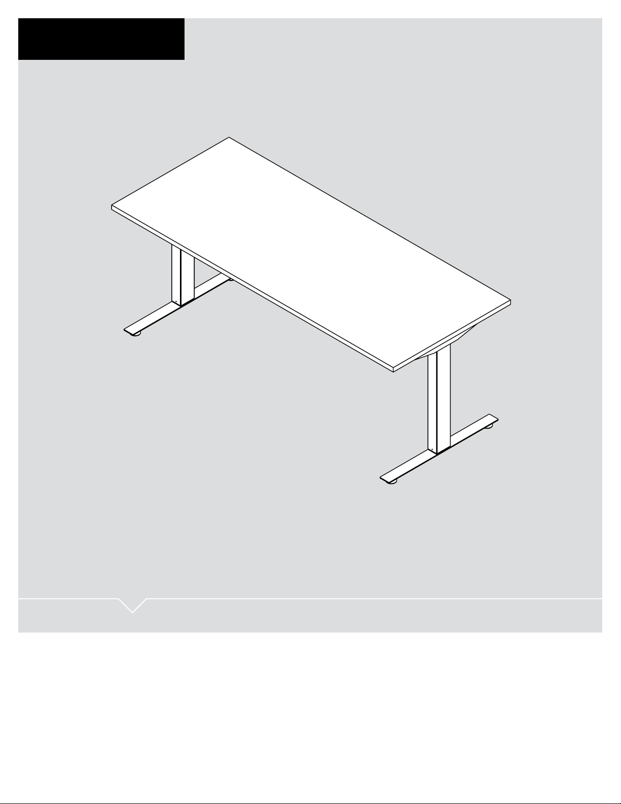
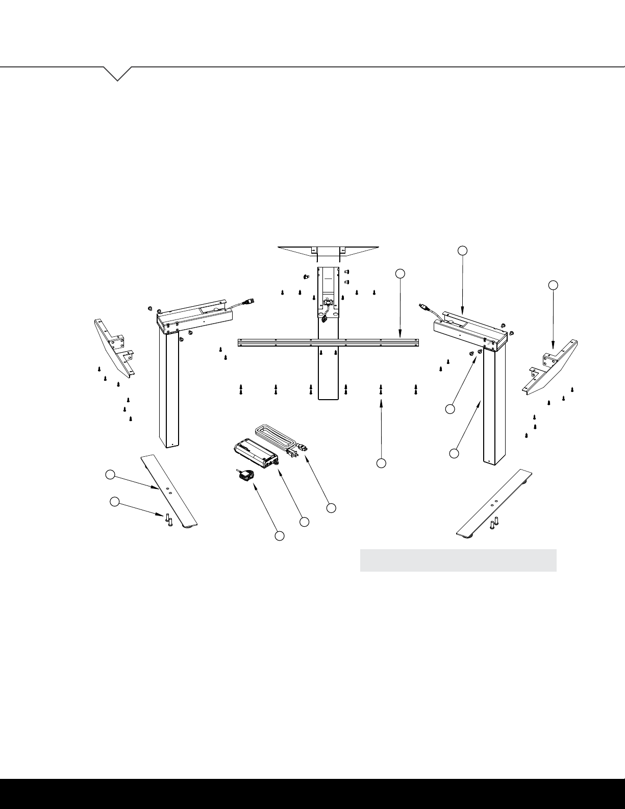
Clever OV1000 User manual

USER GUIDE
OV1000 | Part No. 23624
OV1000
HEIGHT ADJUSTABLE TABLE

2 | OV1000
User Guide: OV1000
OV1000
HEIGHT ADJUSTABLE TABLE
FEATURES
• Meets BIFMA X5.5 standards
• UL 962 approved
• Adjustable frame
• Six color options
• Holds up to 200 lb. load (two-leg) or 250 lb. (three-leg)
A healthier work environment starts with the option to sit or stand
throughout the day. Our OV1000 table is the industry standard in
height-adjustable products, and your rst step towards improving
the efciency and well-being of your organization.
This kit supplies everything you need to assemble your
height-adjustable table base. Just add your own work surface
to personalize.
PRODUCT OVERVIEW

OV1000 | 3
User Guide: OV1000
Parts Diagram 4-8
Full Length 4
Independent 5
Independent with HAT Channel 6
Three-Leg: 90 Degree 7
Three-Leg: 120 Degree 8
Safety Information 9-10
Assembly Instructions 11-17
Operation 18-19
Initialization and Reset 18
Handswitch Operation 18
Programmable Handswitch Operation 18
- Change the Height Unit 19
- Adjust Height Display 19
- Save Memory Position 19
- Recall Memory Position 19
Troubleshooting 20-21
Unit Errors 20
Handswitch Errors 21
Technical Data 22
Warranty 23
Standards & Certications 23
TABLE OF CONTENTS
TABLE OF CONTENTS
This manual explains how this sit-stand desk is assembled, used, and maintained.
All sit-stand tables are subjected to functional and quality tests before leaving
our facility.

4 | OV1000
User Guide: OV1000
OV1000
PARTS DIAGRAM
1
5
3
10
2
6
4
7
8
9
PARTS Qty/Package
1. Beam 1
2. Column 2
3. Top Support 2
4. Foot 2
5.
M8x1.25 12mm Self-Threading Screw
8
6. M10x1.5 30mm Screw 4
7. Handswitch 1
8. Control Box 1
9. Power Cord 1
10. #10 x ¾ Screw 24
FULL LENGTH
For tables up to 84"
PARTS DIAGRAM
DO NOT remove the foam
surrounding the motor.

OV1000 | 5
User Guide: OV1000
3
5
1
4
2
6
7
9
10
8
PARTS Qty/Package
1. Independent Beam 2
2. Column 2
3. Top Support 2
4. Foot 2
5.
M8x1.25 12mm Self-Threading Screw
8
6. M10x1.5 30mm Screw 4
7. Handswitch 1
8. Control Box 1
9. Power Cord 1
10. #10 x ¾ Screw 24
INDEPENDENT
For tables 60" or Less
PARTS DIAGRAM
DO NOT remove the foam
surrounding the motor.

6 | OV1000
User Guide: OV1000
PARTS Qty/Package
1. Independent Beam 2
2. Column 2
3. Top Support 2
4. Foot 2
5. HAT Channel 1
6.
M8x1.25 12mm Self-Threading Screw
8
7. M10x1.5 30mm Screw 4
8. Handswitch 1
9. Control Box 1
10. Power Cord 1
11. #10 x ¾ Screw 32
PARTS DIAGRAM
INDEPENDENT WITH HAT CHANNEL
For tables 60"−84"
DO NOT remove the foam
surrounding the motor.
5
1
6
11
3
2
4
7
8
10
9

OV1000 | 7
User Guide: OV1000
1
3
2
4
6
7
5
11
10
9
8
PARTS Qty/Package
1. Support Beam 2
2. Independent Beam 3
3.
M8x1.25 12mm Self-Threading Screw
12
4. Top Support 3
5. Column 3
6. Foot 3
7. M10x1.5 30mm Screw 4
8. #10-15
3/4" Screw 69
9. Handswitch 1
10. Control Box 1
11. Power Cord 1
PARTS DIAGRAM
THREE-LEG: 90 DEGREE
For tables up to 72"
DO NOT remove the foam
surrounding the motor.

8 | OV1000
User Guide: OV1000
PARTS DIAGRAM
1
2
8
4
5
3
9
10
11
7
6
PARTS Qty/Package
1. Support Beam 1
2. Independent Beam 3
3.
M8x1.25 12mm Self-Threading Screw
12
4. Top Support 3
5. Column 3
6. Foot 3
7. M10x1.5 30mm Screw 4
8. #10-15
3/4" Screw 56
9. Handswitch 1
10. Control Box 1
11. Power Cord 1
THREE-LEG: 120 DEGREE
For tables up to 60"
DO NOT remove the foam
surrounding the motor.

OV1000 | 9
User Guide: OV1000
1
2
8
4
5
3
9
10
11
7
6
SAFETY INFORMATION
1"
1"
1"
1"
1"
1"
SAFETY
INFORMATION
INSTALL ONLY APPROVED WORK SURFACES
This table system does not include a work surface (desktop). Work surface must be at least ¾" thick and weigh no
more than 5 lb. per square foot (For example, a 2'x6' desktop should weigh no more than 60 lb). Do not exceed a
maximum weight for the desktop of 75 lb. To prevent table from tipping or collapsing, make sure the desk frame
is not overloaded by the weight of tabletop and objects you plan to put on the table. If you are unsure, contact
customer service.
KEEP AWAY FROM CHILDREN
This table system is not designed for use in homes or other areas accessible by small children.
For indoor commercial ofce use only.
BE CAREFUL WHEN ADJUSTING DESK HEIGHT
Body parts and property can be caught between the
moving work surface and an immobile obstacle (such as
shelves, furniture, window sills, or walls). Keep at least
one inch of clearance around desk and make sure nothing
is in table’s path for its entire range of motion.
Before raising or lowering:
• Check surroundings on all sides of desk are clear
• Make sure corded objects will not be pulled off table
or cause other objects to fall
• Make sure desk power cord moves freely
as desk moves up and down
IMPORTANT SAFETY INSTRUCTIONS Save these instructions.
DANGER
To reduce the risk of electric shock:
Always unplug this furnishing from the electrical outlet before cleaning.
WARNING:
To reduce the risk of death, serious injury, or property damage, read and
follow this safety information and the provided instructions when assembling this product.
Do not change or replace components and accessories provided by OMT-Veyhl.

10 | OV1000
User Guide: OV1000
SAFETY INFORMATION
DO NOT OVERLOAD DESK
To prevent table from tipping or collapsing, make sure the desk frame is not overloaded by the weight
of tabletop and objects on table. Evenly distribute load; excess loads near edges can reduce stability
and lead to tip over.
• Do not exceed maximum load (including weight of desktop) of 200 lb. (91Kg) for two-leg conguration,
and 250 lb. (113 Kg) for three-leg conguration
• Do not exceed edge load of 25 lb. when positioning monitors or mounting accessories.
• Do not sit or stand on table
USE CARE WHEN MOVING DESK
• Clear objects and equipment from table before moving to reduce the risk of tipping over.
• Adjust the desk to its lowest height before moving
• To disconnect, remove plug from outlet
• Do not move a loaded desk
DO NOT OPEN ELECTRICAL COMPONENTS
Do not attempt to service table components. There are no user-serviceable parts inside the motor control
units or table legs. If your table needs service, contact customer service. Never operate this workstation
if it has a damaged cord or plug.
KEEP TABLE FRAME DRY
Keep all electrical components away from water and high humidity. Clean only with a dry or
slightly damp cloth. Do not spray cleaning solutions directly onto table system.
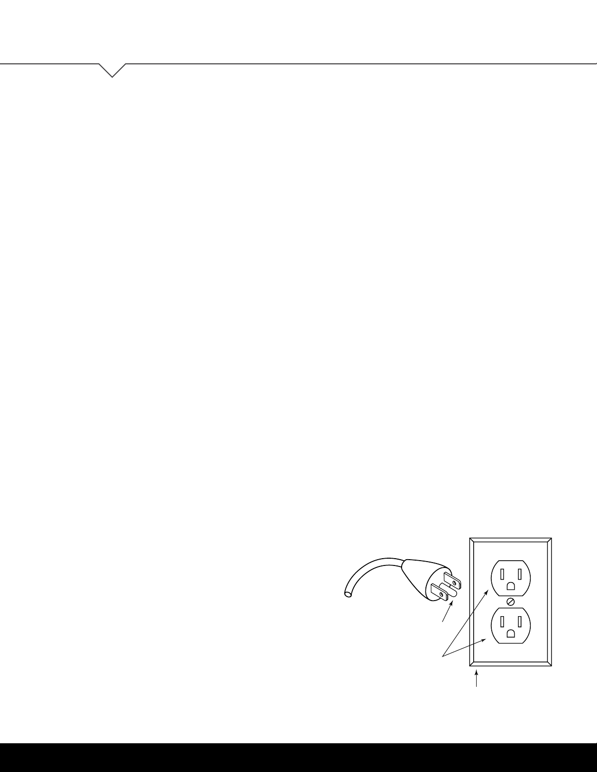
GROUNDING INSTRUCTIONS
This product is equipped with a cord having an
equipment-grounding conductor and a grounding plug.
Use only the cord provided. Make sure that the product
is connected to an outlet having the same conguration
as the plug (as shown in Illustration A) that is properly
installed and grounded in accordance with all local
codes and ordinances.
Do not modify the plug provided with the product
– if it will not t the outlet, have a proper outlet
installed by a qualied electrician.
No adapters are to be used with this product.
Keep cord away from heated surfaces.
Grounded
Outlet
Grounded Outlet Box
Grounding
Pin
Grounded
Outlet
Grounded Outlet Box
Grounding
Pin
ILLUSTRATION A

OV1000 | 11
User Guide: OV1000 ASSEMBLY INSTRUCTIONS
ASSEMBLY
INSTRUCTIONS
ASSEMBLY OVERVIEW 1. Fasten the top support onto the table top
(independent beams only)
2. Assemble the beam and column to the top support
3. Assemble the foot to the column
4. Fasten the table frame onto the table top
5. Fasten the control box and handswitch to the table top
6. Connect the motor cables to the control box
7. Connect the handswitch (HS) cable to the control box
8. Connect the supplied power cord (AC) to the control box
9. Attach all cables to the table frame or on the underside
of the table top
DO NOT remove the foam surrounding the motor.
If you have any difculty assembling this unit, or need to order
replacement parts, please contact our Customer Service department.
Use the parts diagrams on page 4-8 as a reference.
The assembly of the table frame to be made in accordance with this manual.
Changes to the table frame or improper use may affect the safety, function, and life of your product.
This manual is for all sit-stand tables from the OV1000 series.
Due to different models or types, pictures may vary.

12 | OV1000
User Guide: OV1000
ASSEMBLE THE BEAM AND COLUMN
TO THE TOP SUPPORT
Ensure the mounting holes in the column remain aligned
with the corresponding holes in the beam or independent
beam.
Align the beam (Illustration B) or independent beam
(Illustration A) to the top support. Assemble using the
M8x1.25 x 12mm length screws (4 per column). An average
fastening torque of 8Nm (6 lbs-ft) will be
required to initially
engage the screw in the hole. The maximum
tightening torque
for these screws is 20Nm (15 lbs-ft). Repeat as necessary for
remaining columns.
Note: Feed the motor cables through the beam before
attaching the beam to the top support and column.
(FOR INDEPENDENT BEAMS ONLY)
FASTEN THE TOP SUPPORTS ONTO THE TABLE TOP
Be sure top supports are mounted 1.5" from edge of
work surface.
ASSEMBLY INSTRUCTIONS
2
1
ILLUSTRATION A

OV1000 | 13
User Guide: OV1000 ASSEMBLY INSTRUCTIONS
ASSEMBLE THE FOOT TO THE COLUMN
Assemble using the M10x1.5 x 30mm length screws
(2 per column). The maximum tightening torque for
these screws is 48Nm. (35 lbs-ft).
3
ILLUSTRATION B

14 | OV1000
User Guide: OV1000
ASSEMBLY INSTRUCTIONS
1.5 in
FASTEN THE TABLE FRAME ONTO THE TABLE TOP
Be sure to use approved screws per the table top supplier.
4
INDEPENDENT*
INDEPENDENT WITH HAT CHANNEL*
FULL LENGTH
*Please make sure top supports are mounted 1.5"from edge of work surface.
Note: Feed the motor cables through the
HAT channel before attaching the HAT
channel to the top support and column.

OV1000 | 15
User Guide: OV1000 ASSEMBLY INSTRUCTIONS
THREE-LEG: 90 DEGREE
THREE-LEG: 120 DEGREE
3.4in
1in
3.4in
1in
8.7in
A
45°
3.9in
3.9in
A
B
1.9in
1in
5in
120°
1in
3.4in
A
21.9in
30°
B
TOP SIZE A
24in 8in
30in 14in
TABLE DEPTH A
24in 24in
30in 30in
TABLE LENGTH B
60in
TABLE LENGTH B
72in

16 | OV1000
User Guide: OV1000
ASSEMBLY INSTRUCTIONS
FASTEN THE CONTROL BOX AND
HANDSWITCH TO THE TABLE TOP
Make sure the control box and handswitch are
fastened in a location where all the cables will
connect without being in tension. Be sure to use
approved screws per the table top supplier.
5
CONNECT THE MOTOR CABLES
TO THE CONTROL BOX
The motor cable plug-connection has to
click into place.
Connections to the control box:
M1-M2 = Connectors for the columns
HS = Connectors for the handset
AC = Connector for the power cord (3-pin)
6

OV1000 | 17
User Guide: OV1000 ASSEMBLY INSTRUCTIONS
CONNECT THE HANDSWITCH (HS) CABLE
TO THE CONTROL BOX
7
CONNECT THE SUPPLIED POWER CORD (AC)
TO THE CONTROL BOX
ATTACH ALL CABLES TO THE TABLE TOP
Attach cables in order to avoid any damage during
operation. Never attach cables and cords to legs.
8
9

18 | OV1000
User Guide: OV1000
OPERATION
INFORMATION
INITIALIZATION/RESET
The desk must be initialized/reset after any of the following:
- After assembly
- After disconnection from the power supply
- After any impact on the table top.
To initialize/reset, move the table to the lowest position by pressing the DOWN button on the handswitch until
the columns reach the lowest position. Press the DOWN button again until the table moves slightly down to
the machine zero point and back up to the operation zero point. Release the DOWN button. If the button is
released too soon, the table legs will not move up. Repeat the reset process.
The control box is programmed with a parameter le which controls the table legs' lower and upper travel
limits. Under no circumstance should a control box from one table be moved to another.
NORMAL HANDSWITCH OPERATION (for all handswitch types)
By pressing the UP or DOWN buttons, the table will move up or down to the desired position. Once the
desired position is reached, let go of the UP or DOWN button. The table legs will stop once they reach
the lower or upper height limits.
PROGRAMMABLE HANDSWITCH OPERATION (optional)
This programmable handswitch is
equipped with a display for showing
the current table height in centimeters
or inches.
The handswitch also will display an error code if an error is detected by the control box. When an error
is detected, the display will show an error code “EXX,” instead of the current table height. To resolve the
error, see the Troubleshooting Section (p. 20-21 of this guide).
The programmable handswitch also has the ability to save up to four different height positions.
OPERATION INFORMATION
1
s
2 3 4

OV1000 | 19
User Guide: OV1000
PROGRAMMABLE HANDSWITCH OPERATION (continued)
CHANGE THE HEIGHT UNIT (inches or centimeters)
The handswitch can display the table height in either centimeters or inches. With the help of the S5-menus,
the unit of measure can be changed.
To change the unit of measure, follow these steps:
1. Press and hold the 1, 2, and UP buttons until the display shows “S 5”.
2. Conrm by pressing the “S” button. Now the display will have changed.
To exit the menu without making a selection, wait until the height display appears again.
CHANGE THE HEIGHT DISPLAY
If the displayed value does not match the actual height of the table top, the display can be corrected as follows:
1. Press and release the “S” button.
2. Press and hold the DOWN button until the display starts to ash.
3. Change the height shown on the handswitch by pressing the UP or DOWN button to the desired height.
Conrm by pressing the “S” button.
To exit the menu without making a selection, wait until the height display appears again.
SAVE MEMORY POSITION
1. Move the table up or down to the desired height.
2. Press the “S” button (in the display “S -” is shown.)
3. Select a position by pressing one of the four number buttons, 1-4, (the display will show the setting as “S1”).
4. The saved position is conrmed by a double click sound from the control box. The display shows the current table
height. Repeat steps to save a maximum of four different positions.
RECALL MEMORY POSITION
Press and hold the desired memory button (1, 2, 3 or 4) the table moves from the current position into the saved
position. The button must be pressed until the position is reached. If the button is released, the table will stop short
of the desired height.
OPERATION INFORMATION

20 | OV1000
User Guide: OV1000
TROUBLESHOOTING
UNIT
TROUBLESHOOTING
ERROR CODE
SOURCE SOLUTION
Table does not
move
No power supply Plug in the power cord or check the connection
on the control box
No connection or a loose
connection to the drives
Verify the plug connections of the motor cable
to the control box
No connection or a loose
connection to the handswitch
Verify the plug connections of the motor cable
to the control box
Max lifting capacity
is exceeded
Reduce the weight or load on the desktop
Replace the handswitch
Max time limit is exceeded Control is activated automatically after approx. 9 minutes
Defective drive Contact customer service
Defective control box Contact customer service
Defective handswitch
Contact customer service
Defective drive
Table moves
down at a
slow rate
Control box expects
new reset Reset control box. (See page 18)
During operation,
tables moves at
a slow rate
Max lifting capacity
is exceeded Reduce weight
Table moves
on one side only
briefly and then
stops
No connection or a loose
connection to the drives
Verify the plug connections of the motor cable
to the control box and reset the control box
Table of contents
Popular Indoor Furnishing manuals by other brands

Canvas
Canvas MONACO 088-1787-4 Assembly instructions

BLACK RED WHITE
BLACK RED WHITE INDIANA JSZF 3d2s Assembly manual

LUXE BIDET
LUXE BIDET Sophea installation manual

URBAN OUTFITTERS
URBAN OUTFITTERS ALONZO BED Assembly instructions

Trasman
Trasman Graham MSPACE 5035 Assembly manual

Broyhill
Broyhill Magazzino HV-1204 Assembly instructions

HOMCOM
HOMCOM 713-094V90 Assembly & instruction manual

BLACK RED WHITE
BLACK RED WHITE NIKA 250 FRONTY SOFT Assembly manual

Bonaldo
Bonaldo Sol Assembly instruction

Medline
Medline MOBILE 100 RECLINER owner's manual

Next
Next RUBIX WIDE CHEST Assembly instructions

Bouclair
Bouclair 9395444 Assembly instructions