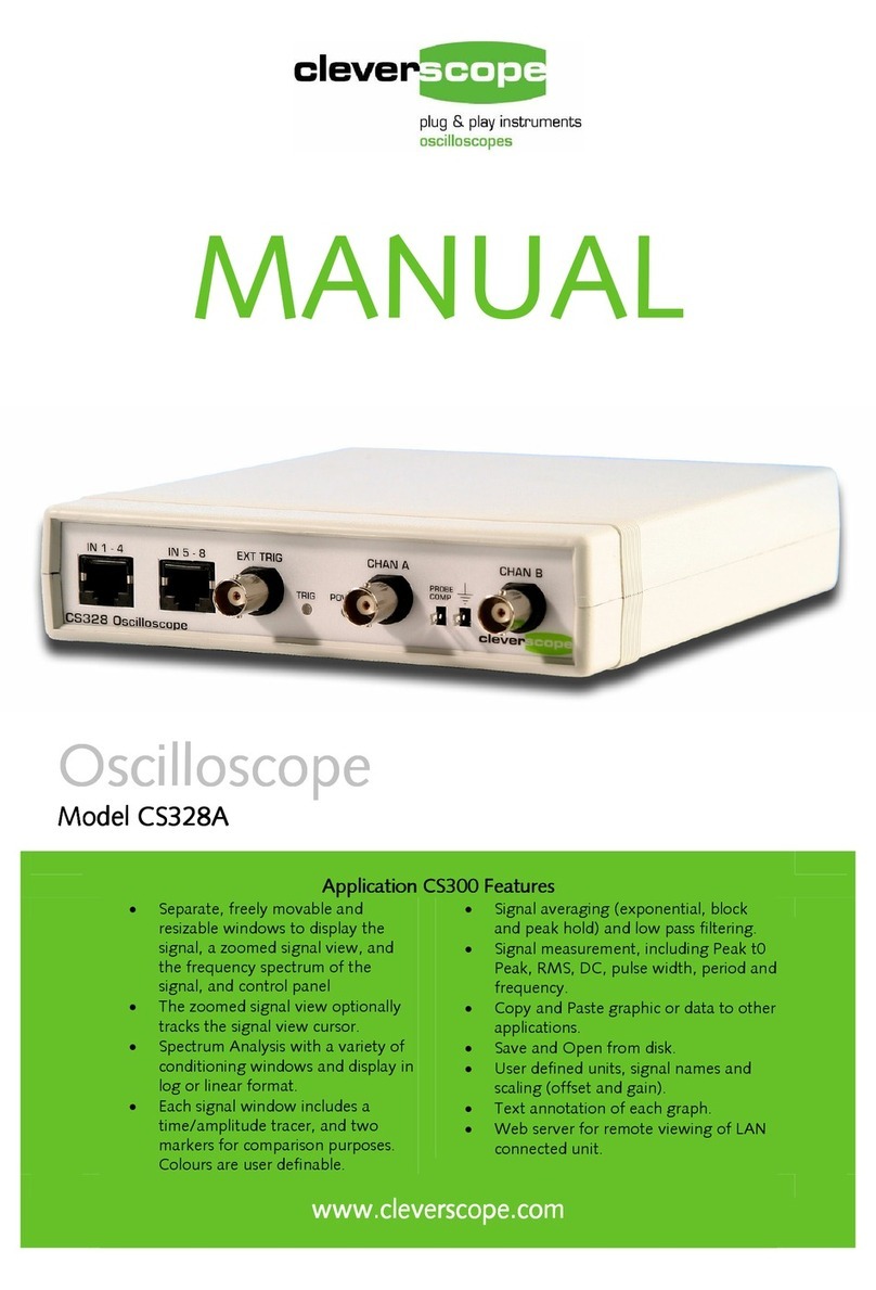
Cleverscope CS300 User manual

Oscilloscope
Reference Manual
CS300
Cleverscope Models:
CS320 CS328
CS320A CS328A
CS320AE CS328AE
CS320A-XS CS320-XSE
v 2.13.0 10 June 2017

Cleverscope CS300 Reference Manual v2.11
Page 2 www.cleverscope.com ©Cleverscope 2004-2015

v2.13 Cleverscope CS300 Reference Manual
©Cleverscope 2004-2018 www.cleverscope.com Page 3
Table of Contents
1SAFETY...........................................................................................................................10
2OVERVIEW......................................................................................................................11
3GETTING STARTED........................................................................................................14
3.1 Unpack............................................................................................................................................................14
3.2 Install Cleverscope Application Software....................................................................................................14
3.3 Power up the Cleverscope Acquisition Unit (CAU) ....................................................................................14
3.4 Connect the CAU to the PC - USB ...............................................................................................................14
3.5 Connect the CAU to the PC - Ethernet........................................................................................................14
3.6 Acquire a Signal for Display .........................................................................................................................15
3.7 Compensate Probes........................................................................................................................................17
3.8 Changing the Trigger Edge...........................................................................................................................18
3.9 Setting Trigger Level.....................................................................................................................................18
3.10 Adjusting the Scope Display .........................................................................................................................19
3.11 Signal Generators ..........................................................................................................................................20
3.12 Keyboard Shortcuts –Quick Reference.......................................................................................................21
4CLEVERSCOPE CONTROL PANEL...............................................................................22
4.1 Cleverscope Tools Zone [Control Panel] .....................................................................................................22
4.2 ACQUIRE Zone [Control Panel]..................................................................................................................24
4.3 DISPLAY Zone [Control Panel]...................................................................................................................27
4.4 TRIGGER 1 Zone [Control Panel]...............................................................................................................29
4.5 Trigger 2 Settings (Ctrl+T) [Control Panel]................................................................................................30
4.6 Trigger 1~2 Zone [Control Panel] ................................................................................................................31
4.7 Digital Pattern Triggering Zone [Control Panel]........................................................................................32
4.8 Decode Protocol zone [Control Panel]..........................................................................................................32
5CONTROL PANEL - MENUS ..........................................................................................33
5.1 File Menu [Control Panel].............................................................................................................................34

Cleverscope CS300 Reference Manual v2.11
Page 4 www.cleverscope.com ©Cleverscope 2004-2015
5.2 Edit Menu [Control Panel]............................................................................................................................39
5.3 Settings Menu [Control Panel] .....................................................................................................................39
5.4 View Menu [Control Panel] ..........................................................................................................................58
5.5 Window Menu [Control Panel].....................................................................................................................59
5.6 Help Menu [Control Panel]...........................................................................................................................59
6SCOPE DISPLAY [VIEW MENU] ....................................................................................60
7TRACKING DISPLAY [VIEW MENU]..............................................................................61
7.1 How the Tracking Display Works................................................................................................................61
8SPECTRUM DISPLAY [VIEW MENU].............................................................................62
8.1 Spectrum Display Tracer and Markers.......................................................................................................63
9CLEVERSCOPE DISPLAYS –DISPLAY CONTROL BUTTONS...................................64
9.1 Display Buttons - Vertical Axis.....................................................................................................................64
9.2 Zooming the Graph .......................................................................................................................................66
10 CLEVERSCOPE DISPLAYS - TRACERS AND MARKERS ...........................................67
10.1 Tracers............................................................................................................................................................67
10.2 Setting Analog Markers ................................................................................................................................67
10.3 Digital Tracers and Markers ........................................................................................................................68
10.4 Setting Digital Markers.................................................................................................................................68
10.5 Using Markers to Measure Differences and Frequency.............................................................................69
10.6 Cleverscope Displays - Frame and Trigger Time Stamp............................................................................69
10.7 Cleverscope Displays - Graph Tools.............................................................................................................69
11 PERSISTENCE................................................................................................................71
11.1 Example Plots.................................................................................................................................................72
11.2 Persistence Plots.............................................................................................................................................73
11.3 Eye-diagram Plots..........................................................................................................................................74
11.4 Performance...................................................................................................................................................74
11.5 Conclusion ......................................................................................................................................................74

v2.13 Cleverscope CS300 Reference Manual
©Cleverscope 2004-2018 www.cleverscope.com Page 5
12 STREAMING....................................................................................................................75
12.1 Capturing a Stream.......................................................................................................................................75
12.2 Reviewing the Stream....................................................................................................................................77
12.3 Protocol decoding a stream...........................................................................................................................79
12.4 Tracking and Maths Display of a Stream....................................................................................................80
12.5 Spectrum Display of a Stream ......................................................................................................................81
12.6 Open a Stream File ........................................................................................................................................81
13 SIGNAL INFORMATION [VIEW MENU]..........................................................................82
13.1 Signal Information Display...........................................................................................................................82
13.2 Signal Information –Show Logging Button (Scope source).......................................................................82
13.3 Signal Information –Waveform Functions (Scope Source).......................................................................83
13.4 Signal Information –Pulse Functions (Scope source).................................................................................84
13.5 Signal Information Display –Spectrum Functions (Spectrum source).....................................................85
13.6 Signal Information Display –Spectrum FRA Functions (Spectrum source)............................................85
13.7 Dynamic Data Exchange (DDE) ...................................................................................................................86
13.8 Using Logging.................................................................................................................................................87
14 XY DISPLAY [VIEW MENU]............................................................................................88
14.1 XY Display Controls......................................................................................................................................88
14.2 Using the X-Y Display ...................................................................................................................................88
14.3 Digital Inputs [View Menu]...........................................................................................................................89
15 TRIGGER 2 SETTINGS [VIEW MENU]...........................................................................90
16 CS700A SIGNAL GENERATOR MODULE CONTROLS [VIEW MENU]........................91
16.1 Using the CS700A Signal Generator Module..............................................................................................94
16.2 Connect and Set Up .......................................................................................................................................94
16.3 Acquire the Signal Generator Output..........................................................................................................95
17 FREQUENCY RESPONSE ANALYSER FRA [VIEW MENU].........................................96
17.1 Where to next? ...............................................................................................................................................97
17.2 Connections ....................................................................................................................................................97

Cleverscope CS300 Reference Manual v2.11
Page 6 www.cleverscope.com ©Cleverscope 2004-2015
17.3 Use of the FRA with Power Supplies............................................................................................................98
17.4 Getting Started with the FRA.....................................................................................................................101
17.5 Frequency Response Analyser Control Window.......................................................................................102
18 SIGNAL GENERATOR SIMULATOR [VIEW MENU]....................................................122
18.1 Signal Generator Simulator Control Window ..........................................................................................122
18.2 Using the Signal Generator Simulator.......................................................................................................123
19 MATHS DISPLAY [VIEW MENU]..................................................................................124
19.1 Maths Display...............................................................................................................................................124
19.2 Maths Equation Builder..............................................................................................................................124
19.3 Maths Equation Builder Walkthrough......................................................................................................129
19.4 Example - Power Consumption [Maths]....................................................................................................129
19.5 Example - Deriving the Differential Voltage [Maths]...............................................................................130
19.6 Example - Deriving Current [Maths].........................................................................................................130
19.7 Example - Deriving Power [Maths]............................................................................................................131
19.8 Example - Deriving Energy [Maths] ..........................................................................................................133
20 MATLAB USAGE ..........................................................................................................134
20.1 Matlab .m functions.....................................................................................................................................134
20.2 Setting up a Cleverscope for Matlab..........................................................................................................135
20.3 Matlab Functions - Example 1 Add two channels.....................................................................................136
20.4 Matlab Functions - Example 2....................................................................................................................137
20.5 Matlab Functions - Example 3....................................................................................................................137
20.6 Matlab Functions - Example 4....................................................................................................................138
20.7 Using Matlab for Further Processing.........................................................................................................139
20.8 Conclusion ....................................................................................................................................................139
21 PROTOCOL SETUP......................................................................................................140
21.1 UART Tab....................................................................................................................................................141
21.2 SPI Tab .........................................................................................................................................................142
21.3 I2C Tab.........................................................................................................................................................143

v2.13 Cleverscope CS300 Reference Manual
©Cleverscope 2004-2018 www.cleverscope.com Page 7
21.4 Count Tab.....................................................................................................................................................144
21.5 Using the Protocol Decoder.........................................................................................................................145
21.6 Using the Protocol Decoder - Additional Notes.........................................................................................146
21.7 I2C protocol Example ..................................................................................................................................146
21.8 UART Protocol Example.............................................................................................................................149
21.9 SPI Protocol Example..................................................................................................................................150
22 NOTES [VIEW MENU]...................................................................................................151
23 USING THE ETHERNET CLEVERSCOPE....................................................................152
23.1 Using Cleverscope on a DHCP Network....................................................................................................152
23.2 Using Cleverscope on a Fixed IP Network or Direct Connected to a PC................................................156
23.3 Remote Fixed IP Network...........................................................................................................................159
24 4-CHANNEL CLEVERSCOPE.......................................................................................160
24.1 Binary Version .............................................................................................................................................160
24.2 USB Serial Numbers....................................................................................................................................160
24.3 Program USB Serial Number .....................................................................................................................161
24.4 Connect the Units.........................................................................................................................................161
24.5 Ready the Cleverscope4 Application..........................................................................................................161
24.6 Run the Cleverscope4 Application .............................................................................................................162
25 UPDATING CLEVERSCOPE.........................................................................................164
25.1 Important –Read Before Starting..............................................................................................................164
25.2 Cleverscope Application Software First Time Installation ......................................................................164
25.3 Updating Cleverscope..................................................................................................................................164
25.4 Important –Before Updating .....................................................................................................................165
25.5 Update an existing Cleverscope Application .............................................................................................165
25.6 Using the Cleverscope Application with a Classic CS320/8 .....................................................................168
25.7 Updating Cleverscope Applications Prior to 6430....................................................................................168
25.8 Firmware Update.........................................................................................................................................169
25.9 Ethernet Cleverscope Firmware Update ...................................................................................................170

Cleverscope CS300 Reference Manual v2.11
Page 8 www.cleverscope.com ©Cleverscope 2004-2015
25.10 Update a First Generation Installation......................................................................................................170
25.11 Using Windows 98SE, ME and NT.............................................................................................................170
26 CALIBRATE CLEVERSCOPE (VERSIONS 6442+)......................................................171
26.1 Calibration Functions..................................................................................................................................171
26.2 Once Yearly Calibration .............................................................................................................................171
26.3 Standard Calibration...................................................................................................................................172
26.4 Signal Generator Calibration .....................................................................................................................172
26.5 Digital Inputs Calibration...........................................................................................................................174
26.6 Frequency Response Calibration................................................................................................................174
26.7 Ext Trig Calibration....................................................................................................................................175
27 CLEVERSCOPE SUPPORT..........................................................................................176
27.1 Minimum PC Requirements.......................................................................................................................176
27.2 Evaluation Software ....................................................................................................................................176
28 CLEVERSCOPE SPECIFICATION................................................................................179
28.1 Signal Acquisition........................................................................................................................................179
28.2 Analog Inputs...............................................................................................................................................179
28.3 Vertical..........................................................................................................................................................179
28.4 Horizontal.....................................................................................................................................................180
28.5 Triggering.....................................................................................................................................................180
28.6 Digital Inputs (CS328A)..............................................................................................................................180
28.7 Measurements ..............................................................................................................................................180
28.8 PC Interface .................................................................................................................................................181
28.9 Calibration....................................................................................................................................................181
28.10 Displays.........................................................................................................................................................181
28.11 Mathematical Functions..............................................................................................................................182
28.12 Spectrum Analysis .......................................................................................................................................182
28.13 Protocol Decode............................................................................................................................................182
28.14 Charting........................................................................................................................................................183
28.15 Data Export..................................................................................................................................................183

v2.13 Cleverscope CS300 Reference Manual
©Cleverscope 2004-2018 www.cleverscope.com Page 9
28.16 Windows Facilities.......................................................................................................................................183
28.17 Probe Compensator Output........................................................................................................................183
28.18 Power Source................................................................................................................................................183
28.19 Environmental..............................................................................................................................................183
28.20 Mechanical....................................................................................................................................................184
28.21 Expansion Capability - Signal Generator Module CS700A.....................................................................184
28.22 Expansion Capability –Increase Sampling Channels and Sample Rate ................................................184
28.23 Cleverscope Hardware Resources..............................................................................................................185
28.24 Cleverscope Application Software Resources:..........................................................................................185
29 APPENDIX 1 –DOCUMENT CONTROL.......................................................................186
30 APPENDIX 2 - KEYBOARD SHORTCUTS ...................................................................188

Cleverscope CS300 Reference Manual v2.11
Page 10 www.cleverscope.com ©Cleverscope 2004-2015
1 Safety
Please review the following safety precautions to avoid injury and prevent damage to this product or any
products connected to it.
To avoid potential hazards, use this product only as specified.
Only qualified personnel should perform service procedures.
To Avoid Fire or Personal Injury:
Use Proper Power Adapter. Use only the power adapter specified for this product and certified for the
country of use.
Connect and Disconnect Properly. Do not connect or disconnect probes or test leads while they are
connected to a voltage source.
Connect and Disconnect Properly. De-energize the circuit under test before connecting or disconnecting
the current probe.
Ground the Product. This product is grounded through the grounding conductor of the power cord. To
avoid electric shock, the grounding conductor must be connected to earth ground. Before making
connections to the input or output terminals of the product, ensure that the product is properly grounded.
Observe All Terminal Ratings. To avoid fire or shock hazard, observe all ratings and markings on the
product. Consult the product manual for further ratings information before making connections to the
product.
The inputs are not rated for connection to mains or Category II, III, or IV circuits.
Connect the probe reference lead to earth ground only.
Do not apply a potential to any terminal, including the common terminal, that exceeds the maximum
rating of that terminal.
Power Disconnect. Power adapter disconnection disconnects the product from the power source. Do not block
the power connection; it must remain accessible to the user at all times.
Do Not Operate Without Covers. Do not operate this product with covers or panels removed.
Do Not Operate With Suspected Failures. If you suspect that there is damage to this product, have it inspected
by qualified service personnel.
Avoid Exposed Circuitry. Do not touch exposed connections and components when power is present.
Do Not Operate in Wet/Damp Conditions.
Do Not Operate in an Explosive Atmosphere.
Keep Product Surfaces Clean and Dry.
Provide Proper Ventilation. Ensure the unit has adequate ventilation so the ambient temperature does not
exceed 40 deg. C.

v2.13 Cleverscope CS300 Reference Manual
©Cleverscope 2004-2018 www.cleverscope.com Page 11
2 Overview
The Cleverscope is a PC based mixed signal oscilloscope, spectrum analyser, and signal generator. Signals are
captured by the Cleverscope Acquisition Unit that connects via USB or Ethernet connection to a local PC.
Software in the PC provides a significant functionality not normally unavailable from traditional stand-alone
oscilloscopes.
The Scope display is the main window and, as shown below, contains the normal waveform display together
with an information panel, plus the option for displaying up 8 to digital inputs.
On-screen controls allow the display to be adjusted as required. Tracers are provided to facilitate detailed
measurements.
Cleverscope functionality is resident on the PC. The Cleverscope Application Software implements several
different oscilloscope displays, signal generator controls, spectrum analyser, digital logic analyser, protocol
anaylser, Matlab functionality, and copy and paste facilities for documentation of test results. Graphs and data
can be copied and pasted to other applications, saved or loaded from disk, and printed.
A full technical specification is included at the end of this manual.

Cleverscope CS300 Reference Manual v2.11
Page 12 www.cleverscope.com ©Cleverscope 2004-2015
Cleverscope
Cleverscope has been designing and manufacturing test equipment since 2004. The company is based in
Auckland, New Zealand.
Circuit boards are assembled in a modern RoHS compliant ISO9002 certified manufacturing facility, also in
Auckland.
The RoHS Compliance Statement is available at www.cleverscope.com.
Both Cleverscope models have been tested to comply with CE directives on Electromagnetic Compatibility
(89/336/EEC) and Low Voltage (73/23/EEC).
Cleverscope Models
All Models have 2 Analog Channels, External trigger Input, Cleverscope Application Software, a dual channel
sampler and an interface to the PC.
Cleverscopes are also available in OEM configurations and quantities for embedded applications.
Orders can be placed online via the web site or sent via email or purchased through distributors. Distributors are
listed on the web site.
All Cleverscopes come with a three year warranty from date of manufacture. There is also a Money Back
Guarantee, details of which are on the web site.
USB 2.0 Interface (CS740) Models
CS320A 4M Samples, 10 bit sampler, USB I/O
The CS320A can be upgraded to 8M memory, 12 or 14 bit dual channel sampler, plus signal
generator.
CS328A 4M Samples, 10 bit sampler, 8 digital inputs, USB I/O
The CS328 can be upgraded to 8M memory and 12 or 14 bit dual channel sampler, plus signal
generator.
CS328A-XS 8M Samples, 14 bit sampler, 8 digital inputs, USB I/O, CS700 Signal Generator
Ethernet (Isolated) (CS741) Models
CS320AE 4M Samples, 10 bit sampler, Ethernet I/O
The CS320AE can be upgraded to 8M memory and 12 or 14 bit dual channel sampler plus
signal generator.
CS328AE 4M Samples, 10 bit sampler, 8 digital inputs, Ethernet I/O
The CS328AE can be upgraded to 8M memory and 12 or 14 bit dual channel sampler plus
signal generator.
CS328A-XSE 8M Samples, 14 bit sampler, 8 digital inputs, Ethernet I/O, CS700 Signal Generator

v2.13 Cleverscope CS300 Reference Manual
©Cleverscope 2004-2018 www.cleverscope.com Page 13
Modules
CS800
Upgrade to 8MSample memory
CS810
External Sampler Clock Interface
CS710
100MHz 10 bit dual channel sampler
CS712
100MHz 12 bit dual channel sampler
CS714
100MHz 14 bit dual channel sampler
CS740
USB 2.0 PC Interface module
CS741
Ethernet Interface module
CS700A
Signal Generator (0 –10 MHz, Sine, Square, Triangle)
CS701
Sine Wave Generator 300Vrms isolated (0 –65MHz, sine)
CS1070
Power Amplifier, stand-alone. 50 MHZ Bandwidth, 1A drive current, +/-17V output sine
wave or DC value (using supplied 19V supply) which maybe offset from 0V to +17V by
using a higher voltage input supply (20V - 36V). With a 36V supply the output swings 0 -
34V.
Accessories
CS1001 Analog Probe - 1x, 10x 250MHz
CS1002 Analog Probe –100x 250MHz
CS1003 Analog Probe - 1000x, 50MHz
CS1004 Digital Probe Pod –4bit 100MHz (including probe clips) Colour-coded ports 1-4
CS1004 Digital Probe Pod –4bit 100MHz (including probe clips) Colour-coded ports 5-8
CS1010 50 5ns delay line to connect Channel A to Channel B for 200MSample operation
CS1020 2 port link cable to connect two Cleverscope units for four channel operation
CS1030 Differential Probe 25MHz 1300v
CS1031 Differential Probe 50MHz 6500v
CS1041 USB Isolator
CS1050 Power Supply without 230/110v cable
CS1060 70Amp AD Dc current Probe
Probe sets come complete with the probe tip accessories, compensation adjusting tool, and channel Identifying
clips. Each probe packet includes a frequency response chart.
Upgrades
Upgrades are normally specified at time of ordering and supplied installed ex-factory.
Some modules can be retro-fitted in the field by qualified personnel using antistatic facilities and appropriate
tools. Full instructions are provided by Cleverscope.
Configurations
Cleverscopes are defined by their configuration ID in the form of mem.sps.bit.sig.io where
mem
4 or 8
4MSamples or 8MSamples
sps
10
Speed in 10MSPS unit, 100MSPS = 10
bit
10, 12, or 14
Number of sampler bits
sig
0 or 1
0 not fitted, 1 CS700A fitted 2 701 fitted
io
1 or 2
1 USB, 2 Ethernet

Cleverscope CS300 Reference Manual v2.11
Page 14 www.cleverscope.com ©Cleverscope 2004-2015
3 Getting Started
The Cleverscope is easy to set up and get running once the Cleverscope application software is installed on your
PC.
3.1 Unpack
Cleverscopes are normally supplied as a boxed kit containing the Cleverscope Acquisition Unit, power supply
and power cable, two 1x/10x 250MHz probes, installation Instructions, a Cleverscope Application Software
CDROM, and digital probe sets for the digital versions.
Unpack the box, remove wrapping and discard safely.
3.2 Install Cleverscope Application Software
The Cleverscope Application Software is supplied on the CD that came with the unit.
Install the software by following the instructions on the printed sheet. Do not plug in the Cleverscope while
installing the software.
Minimum requirements are a Pentium PC with at least 256 MB of memory running Windows 7, Windows Vista,
Windows XP or Windows 2000.
3.3 Power up the Cleverscope Acquisition Unit (CAU)
Connect the DC power cable to
POWER IN
, socket on the rear panel.
Note: When you plug the power adapter into the mains the Trig indicator should blink and the Power indicator
should show a steady green. This is the self test completing.
Plug the power adaptor into the mains. Observe the green power light.
3.4 Connect the CAU to the PC - USB
Connect the USB cable to
USB
port
on the rear of the unit
and to the PC.
Note If this is the first time of use, there will be a small delay while Windows finds the drivers.
3.5 Connect the CAU to the PC - Ethernet
For an Ethernet CAU connect the Ethernet cable to the Ethernet port on the rear of the unit and to the
PC/switch/network.
Check the indicator lights on the Ethernet port are illuminated.

v2.13 Cleverscope CS300 Reference Manual
©Cleverscope 2004-2018 www.cleverscope.com Page 15
3.6 Acquire a Signal for Display
Start the Cleverscope application software on the PC.
Cleverscope Displays on Start-up
Enable Channels A & B
Probe Attenuation
On the Cleverscope Control Panel
Click the Enabled buttons for both channel Aand Bso that they both display
Click the Coupling buttons for both channel Aand Bso that they both display
Check the probe attenuation are both set to x1.
Connect probes to Chan A and Chan B and, using the clip accessory, clip the probe tips to the Probe Comp pin
on the CAU front panel, the leftmost of the two pins.
Note: Probe Comp produces a 2v p-p square wave signal for probe frequency response compensation.
Clip the earth clips to the earth pin, the rightmost of the two pins.
Check the probe attenuation slider switch on the probe barrel is set to x1.
Autoset
Click to automatically scale the Scope Display and automatically set the trigger settings
to match the signal you have connected.
Autoset may take a few moments to acquire the signal and work out the correct
display settings.
The result should be similar to the following:

Cleverscope CS300 Reference Manual v2.11
Page 16 www.cleverscope.com ©Cleverscope 2004-2015
Start-up First Capture
Channel A
is displayed in the lower half of the Scope display and is coloured red.
The axis for channel A is on the left.
Channel B
is displayed on the upper half of the Scope display and coloured blue.
Channel B axis is on the Right.
Y-Axis
Note both channels are referenced to ground (0 volts) in their respective scales.
X-Axis
Both displays are shown on a common time axis with ‘0’in the middle of the
graph.
Times to the left of ‘0.0’are before rigger and time after ‘0.0’post trigger.
Triggering
The graph above shows the acquisition has triggered on the falling edge of
channel A at a trigger level of about 1V (984.7382m displayed in the Trigger 1
Level field).

v2.13 Cleverscope CS300 Reference Manual
©Cleverscope 2004-2018 www.cleverscope.com Page 17
3.7 Compensate Probes
This is a good time to compensate your probes.
Go to the Cleverscope Control Panel window.
In the ACQUIRE area, set the Probe attenuation to
x10
.
In the TRIGGER area, set the trigger Level to
1
V.
You should be already viewing the Scope display.
If not the select the Scope display window from the Control Panel Window
menu.
Set the A channel graph axis to include the voltage range 0 to 4V.
Set the time axis to include the range –750 µs to + 750 µs.
Plug the scope probe into the A channel, attach the hook probe tip.
Set the probe switch (on the barrel of the probe) to x10.
Connect the ground crocodile clip to the right hand ground terminal.
Connect the probe to the left hand Probe Comp output terminal.
Go to the Cleverscope Control Panel window.
Click Triggered button and you should see a graph similar to that on the left.
<<<<
Overshoot or Slow Rise-time
Note The graph may have either over-shoot or slow rise-time.
Both overshoot and slow rise-time require correction to compensate the probe
capacitance and ensure a flat frequency response.
On the Control Panel click the Auto button.

Cleverscope CS300 Reference Manual v2.11
Page 18 www.cleverscope.com ©Cleverscope 2004-2015
Compensated
Adjust the small red screw in the body of the BNC connector end of the probe
until the graph is flat. Repeat the process for all oscilloscope probes.
Note You may like to do this on B channel, to familiarize yourself with the B
channel controls.
Reset Probe settings to x1 on Control Panel and probes
3.8 Changing the Trigger Edge
In the captures shown in the previous topics the Cleverscope has triggered on the falling edge. To change this
to trigger on the rising edge go to the TRIGGER area on the Control Panel.
Trigger 1 Slope
Click in the Source field or use the arrows to select the trigger source.
In this instance it is to trigger from channel A (Chan A).
Click on the Slope symbol to toggle to a rising edge trigger.
3.9 Setting Trigger Level
Cleverscope Tools
On the Cleverscope Tools click on either the rising edge or falling edge trigger button.
In addition to setting the trigger to a rising or falling edge it should show a black line
across the display at the voltage level at which the display will attempt to trigger.
You should be able to see the display change to show a trigger on the selected edge.
You can toggle the trigger Edge button and watch the display in the Scope Display
change each time.

v2.13 Cleverscope CS300 Reference Manual
©Cleverscope 2004-2018 www.cleverscope.com Page 19
Adjust the trigger level by dragging the line to the required point. A small Rising or
Falling edge symbol will appear on the graph. Click and drag the line to the required
voltage level.
You can also type the trigger value directly into the Level window. Here we have
entered 700 mV.
3.10 Adjusting the Scope Display
You can set up the acquisition manually to fine tune what Autoset has initially selected. Display controls are
placed on the on the sides and bottom of the Scope display.
Use the up ( ) and down ( ) vertical display buttons and the vertical expand ( )
and contract ( ) buttons for channel A to size the displayed waveform the way you
would like to see it.
Vertical Axis Setting
As an example you could select 0.50 volts per major horizontal gridline as shown to the
left.
You can also over-type the end values of the displayed axis to change the axis as you
want. Value are in the current scale. If, for example, the left hand time axis displays
-1500, and the display units are us, you can overtype -3000 to change the left hand
end to -3000 us. Hit Enter to register the change.
Go to the Cleverscope Control Panel window.
In the AQUIRE area, click the Single button to acquire a single frame of signal data.
The Scope Display will then display the acquired signal. In the example below, the the
trigger is at 700 mV.
The auto-fit buttons ( and ) for channel A and B can be used to bring the signal
traces into view. Cleverscope will apply the optimum vertical scaling and positioning for
the signal data.
For the vertical scale, the positioning and scaling of the signal trace with respect to time
can be altered using the horizontal display buttons
The screen at left shows the capture after the Channel A auto-fit
button was clicked.

Cleverscope CS300 Reference Manual v2.11
Page 20 www.cleverscope.com ©Cleverscope 2004-2015
Time Axis
Contract Time
The screen at left shows the capture after the Channel A Contract Time
button was clicked.
The display will adjust each time the button is clicked.
Note The trigger point is always positioned at time zero on the
horizontal axis.
The screen at left shows the capture after the Channel A Expand Time
button was clicked.
The display will adjust each time the button is clicked.
Channel B behaves the same as Channel A.
3.11 Signal Generators
If you ordered your Cleverscope to be supplied with the CS700A Signal Generator module fitted you can now
use that to experiment further with capturing signals at different frequencies and wave shapes (sine, square and
triangle).
Chapter 11, CS700A Signal Generator Module Controls describes the use of the Signal Generator module.
(Note you can upgrade your Cleverscope to include the CS700A if it wasn’t fitted ex-factory.)
You can also use the internal Signal Generator Simulator to experiment further with capturing signals at
different frequencies and wave shapes.
Chapter 12, Internal Signal Generator Simulator describes the use of the internal software Signal Generator
Simulator. Note the Simulator is software only and the connection to the Channel A & B inputs is done internally
so no external connections are required. You cannot use the simulator for testing external units.
This manual suits for next models
8
Table of contents
Other Cleverscope Test Equipment manuals
Popular Test Equipment manuals by other brands

Rohde & Schwarz
Rohde & Schwarz CMW-KM750 user manual
Tektronix
Tektronix TDS5000B Series Quick start user manual
OTC
OTC 3052S PARTS LIST & OPERATING INSTRUCTIONS
Anritsu
Anritsu SQA-R MP1900A Product introduction
Distek
Distek Evolution 6300 Operation manual

PRESTON PRESSURE
PRESTON PRESSURE PS-500 User and maintenance manual
