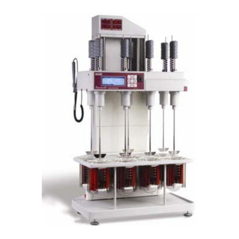
Distek Evolution 6300 User manual

Operation
Manual
Evolution
Dissolution Test
System
6100
6300

Evolution Dissolution Test System
Operation Manual
Document # 3861-0001
Distek, Inc.
121 Nort Center Dr. • Nort Brunswick, NJ 08902
P one 732.422.7585 • Fax 732.422.7310
ttp://www.distekinc.com

Notice
This document contains proprietary information. All ri hts are
reserved. No part of this document may be photocopied,
reproduced or translated without the prior written consent of
Distek, Inc.
Distek, Inc.
121 North Center Drive
North Brunswick, NJ 08902-4905
Tel. (732) 422-7585
Fax. (732) 422-7310
Website: http://www.distekinc.com
“Dow Corning” is a registered trademark of Dow Corning Corporation, USA.
CenterC ek, Heig tC ek, RPMC ek, S aftC ek and TempC ek are trademarks of Distek,
Inc.
T e Distek logo is a registered trademark of Distek, Inc.
All ot er company and product names are trademarks or registered trademarks of t eir
respective olders.
Document Revision History
Rev Date Notes
A June 2003 Initial Release
B December 2003 See Distek C ange Notice 0405
C October 2004 Updated for Firmware Rev. 2.13. See Distek C ange Notice
0456.
D June 2005 Updated Appendix A: Spare Parts & Accessories. See Distek
C ange Notice 0508.
E September 2005
Removed Certificate of Compliance from Manual. Certificate
is a separate file on manual CD. See C ange Notice 0516.
Page B-1: Step # 5.3 – c ange “0.3V” to “2.0 V” and “0.5 V”
to “3.0 V”
Page D-2 and D-3 – add note to bottom of page - “Asterisk (*)
in Temperature Profiles denotes out of USP specification”
F May 2007 See Distek C ange Notice 0580. Updated for FW Rev. 2.15.

Operation Manual: Evolution Series
Contents
About this Manual......................................................................... i
Purpose .................................................................................. ii
Audience ................................................................................ ii
Contents................................................................................. ii
Prerequisites............................................................................iii
Documentation .........................................................................iii
Conventions.............................................................................iii
1Introduction ..................................................................... 1-1
Overview .............................................................................. 1-2
Specification.......................................................................... 1-2
P ysical Site Considerations........................................................ 1-4
Environmental Considerations ..................................................... 1-5
Distek & t e WEEE Directive (Waste Electrical & Electronic Equipment) 1-5
Ambient Laboratory Temperatures ............................................. 1-5
Ambient Laboratory Humidity ................................................... 1-6
Air Quality Considerations ....................................................... 1-7
Operation Warnings and Notes..................................................... 1-8
General Instrument Overview .....................................................1-11
2Installation....................................................................... 2-1
Unpacking ............................................................................. 2-2
Leveling t e Evolution System ..................................................... 2-3
Installing t e T ermocirculator (Evolution 6300 Only) ......................... 2-6
Placement and Connections ..................................................... 2-7
Filling t e Water Bat ............................................................ 2-8
Priming t e Pump ................................................................. 2-8

Operation Manual: Evolution Series
Positioning t e Vessels .............................................................2-10
Paddle and Basket Installation ....................................................2-11
Paddle Blade Installation........................................................2-11
Basket Installation ...............................................................2-11
C ecking Paddles, Baskets and S afts for Straig tness.....................2-12
C ecking S aft Centering .......................................................2-12
Paddles and Basket Heig t Adjustment..........................................2-12
Initial Heig t Setting for Paddles and Baskets: ..............................2-13
Quick C ange Heig t Adjustment Knob (Paddles or Baskets)..............2-14
Installing t e Calibration Probe...................................................2-14
Installation C eckout...............................................................2-15
RPM Control .......................................................................2-15
Test Duration .....................................................................2-15
Temperature Control ............................................................2-16
Time and Date ....................................................................2-16
3Operation ........................................................................ 3-1
Control Keypad ....................................................................... 3-4
ESC/DEL Button.................................................................... 3-4
RUN/STOP Button ................................................................. 3-4
Arrow Keys ......................................................................... 3-4
ENTER Button ...................................................................... 3-4
+ Button ............................................................................ 3-5
- Button............................................................................. 3-5
Stir LED ............................................................................. 3-5
Heat LED............................................................................ 3-5
Sleep LED........................................................................... 3-5
produKEY ........................................................................... 3-5
Startup Screens....................................................................... 3-5
System Administration .............................................................. 3-6
System Setup....................................................................... 3-7
Advanced Options .............................................................. 3-8
Unit Address ..................................................................... 3-8
TCS Address (Evolution 6300 Only)........................................... 3-9
Pre eat (Evolution 6300 Only) ................................................ 3-9
Temperature Control (Evolution 6300 Only)............................... 3-10
Beep Mode ...................................................................... 3-10
Heig t Switc Setting ......................................................... 3-10
Printer S aring Configuration (Evolution 6100 Only) ..................... 3-11
About Window.................................................................. 3-12
User Configuration ...............................................................3-12
Login Procedures .............................................................. 3-13
Creating a New Account ...................................................... 3-14
C anging t e Privileges of an Existing Account ........................... 3-15
C anging a Password .......................................................... 3-15
Deleting an Account........................................................... 3-16
Temperature Calibration........................................................3-16

Operation Manual: Evolution Series
Calibrate Using Evolution Calibration Probe............................... 3-18
Calibrate Using TempC ek Digital T ermometer ......................... 3-19
Calibrate Using NIST-Traceable Reference T ermometer ............... 3-19
Calibrate calPROBE Using TempC ek Digital T ermometer ............. 3-20
Calibrate calPROBE Using NIST-Traceable Reference T ermometer... 3-21
Display Screens ......................................................................3-21
Temperature Screen .............................................................3-21
Temperature and RPM Screen ..................................................3-22
Current Met od...................................................................3-23
Report History ....................................................................3-23
Printing a Saved Report .........................................................3-24
Working wit Met ods (Automatic Mode) .......................................3-24
Selecting a Met od to Run ......................................................3-24
Sorting t e Met od List..........................................................3-25
Programming a New Met od....................................................3-25
Running a Simultaneous Drop wit Paddles ..................................3-27
Running a Simultaneous Drop wit Baskets...................................3-28
Running a Staggered Drop wit Paddles ......................................3-28
Running a Staggered Drop wit Baskets.......................................3-28
Open/View an Existing Met od.................................................3-29
Modify a Saved Met od ..........................................................3-30
Deleting a Met od................................................................3-30
Copy a Saved Met od to a New Name.........................................3-30
Printing Met od Parameters....................................................3-31
Working in Manual Mode ...........................................................3-31
Controlling Vessels Individually (Evolution 6100 Only) .....................3-32
Controlling All Vessels ...........................................................3-33
TCS Activation (Evolution 6300 Only) .........................................3-35
Running a Manual Mode Test ...................................................3-35
Using t e produKEY.................................................................3-36
Saving a Met od to t e produKEY..............................................3-36
Viewing Met ods on t e produKEY.............................................3-37
Saving a Met od from t e produKEY to t e Instrument ....................3-37
Running a Met od from t e produKEY ........................................3-37
Deleting Met ods from t e produKEY .........................................3-38
Printing a Met od from t e produKEY.........................................3-38
Using a Premiere 5100 produKEY ..............................................3-38
Using t e calKEY ....................................................................3-38
Storing Calibration Data.........................................................3-39
Restoring Calibration Data ......................................................3-39
Printouts..............................................................................3-40
Serial Port Control ..................................................................3-40
4Maintenance..................................................................... 4-1
General Information ................................................................. 4-2
Emptying t e Water Bat & TCS (Evolution 6300 Only) ........................ 4-3
Removing t e Water Bat (Evolution 6300 Only)................................ 4-4

Operation Manual: Evolution Series
Re-installing t e Water Bat (Evolution 6300 Only) ............................ 4-5
Replacing t e Water Bat and TCS Tubing (Evolution 6300 Only) ............ 4-5
5Troubles ooting................................................................. 5-1
Troubles ooting ...................................................................... 5-2
Error Messages.......................................................................5-15
Warning Messages...................................................................5-17
General Messages ...................................................................5-18
Service................................................................................5-19
Appendix A : Spare Parts and Accessories ...................................... A-1
Appendix B : Pre-Installation Considerations: Electrical Power SupplyB-1
Appendix C : CE Declaration of Conformity .................................... C-1
Appendix D : Sample Printouts from Parallel Printer ......................... D-1

About T is Manual
Operation Manual: Evolution Series
i
About this Manual
About T is Manual includes information about w at is contained in t is manual and
t e conventions used.
Purpose .................................................................................. ii
Audience ................................................................................ ii
Contents................................................................................. ii
Prerequisites............................................................................iii
Documentation .........................................................................iii
Conventions.............................................................................iii

About T is Manual
Operation Manual: Evolution Series
ii
Purpose
T is manual covers t e installation, routine operation, maintenance and repair of
your Evolution Dissolution Test System. It as information regarding t e
commands, menus, indicators and controls. C apter 1 provides an overview of t e
system. C apter 2 covers unpacking, installation, and qualification of t e system.
C apter 3 as operation and programming information. C apters 4 and 5 cover
maintenance and troubles ooting. Please read C apters 1, 2 and 3 before
proceeding.
Audience
T is manual is written for any person responsible for maintaining, operating or
troubles ooting t e Distek Evolution Dissolution Test System.
Contents
T is manual is divided into c apters. T e pages of t e manual are numbered
providing easy navigation to assist in finding information quickly.
T e following list describes t e material covered in eac c apter:
C apter 1 - Introduction Provides a general overview and
warnings about t e instrument.
C apter 2 - Installation Describes ow to unpack and properly
install t e unit.
C apter 3 - Operation Describes t e functionalities of t e
system and ow to run t e unit.
C apter 4 - Maintenance Explains t e steps necessary to
maintain t e unit.
C apter 5 - Troubles ooting Provides a troubles ooting c art and
description of error messages to assist
t e user if a problem arises.
Appendix A – Spare Parts and
Accessories
Provides a table of recommended and
optional spare parts.
Appendix B - Pre-Installation
Considerations: Electrical Power
Supply
Recommendation information
pertaining to electrical power supply.
Appendix C - CE Declaration of
Conformity
CE Declaration of Conformity
certificate.
Appendix D - Certificate of
Compliance
Certificate of Compliance
Appendix E - Sample Printouts from
Parallel Printer
Sample printouts for a parallel printer.

About T is Manual
Operation Manual: Evolution Series
iii
Prerequisites
T is manual assumes t at you understand t e principles of dissolution testing.
Documentation
T is manual contains important information regarding t e safe operation,
maintenance and repair of your Distek Evolution Dissolution Test System.
Conventions
T e following table contains Warnings, Cautions and Notes t at are used
t roug out t e document for your protection. Please read t is section before
using t e Evolution Dissolution Testing System.
“WARNING” statements are used in t is manual to prevent
injury to personnel.
"CAUTION: Risk of Electric Shock" statements are used to
prevent injury w en ig voltage is present.
“CAUTION” statements are used to prevent damage to
equipment.
“NOTES” contain elpful information.
REQUIRED
ACTION
“REQUIRED ACTION” is used w ere necessary to distinguis
t e action needed from Warnings, Cautions and Notes.

C apter 1: Introduction
Operation Manual: Evolution Series
1
-
1
1
11
1 Introduction
T e Distek Evolution Dissolution Test System is a state of t e art instrument. T is
c apter will provide an overview of t e unit and system specific specifications.
Overview .............................................................................. 1-2
Specification.......................................................................... 1-2
P ysical Site Considerations........................................................ 1-4
Environmental Considerations ..................................................... 1-5
Distek & t e WEEE Directive (Waste Electrical & Electronic Equipment) 1-5
Ambient Laboratory Temperatures ............................................. 1-5
Ambient Laboratory Humidity ................................................... 1-6
Air Quality Considerations ....................................................... 1-7
Operation Warnings and Notes..................................................... 1-8
General Instrument Overview .....................................................1-11

C apter 1: Introduction
Operation Manual: Evolution Series
1
-
2
Overview
Distek is once again setting t e standard by w ic all dissolution systems will be
measured. T e new Evolution Series is taking dissolution testing to t e next level
by advancing t e state of t e art design of its predecessor, t e ig ly successful
Premiere Model 5100.
T e Evolution Series is designed to meet today's demanding standards for accurate
temperature control and test result reporting. T e en anced user interface offers
a ric array of features and functionality, greatly improving t e dissolution
c emist's productivity and control over t e dissolution test. T e Evolution as
menu driven navigation for ease of setup, manager and user log-in levels, 100
sorted met ods and up to 40 test report storage.
Specification
Table 1-1: Evolution Specifications
Evolution 6100
Bathless
Evolution 6300
Water Bath
Dissolution Vessels Six Standard/
Up to Seven Vessels
Six Standard/
Up to Seven Vessels
Volume 500mL - 1000mL
programmable
500mL - 1000mL
programmable
Vessel Heating Rate Approx. 1.5°C per minute Approx. 0.3°C per minute
RPM Control Ran e 25-300 RPM, digitally
controlled, closed loop
25-300 RPM, digitally
controlled, closed loop
Resolution 0.1 RPM 0.1 RPM
Accuracy ±0.2 RPM ±0.2 RPM
Display LED's, .75” (19mm) ig LED's, .75” (19mm) ig
Motor Hig Torque, Permanent
Magnet
Hig Torque, Permanent
Magnet
Vessel Temperature
Control
Independently controlled
two-zone eater jackets
TCS T ermocirculator
Display Resolution 0.01 °C 0.01 °C
Accuracy ±0.25 °C* ±0.25 °C at 37.0 °C
Calibration Built-in Calibration Probe Built-in Calibration Probe

C apter 1: Introduction
Operation Manual: Evolution Series
1
-
3
Evolution 6100
Bathless
Evolution 6300
Water Bath
Shaft Wobble Less t an 0.010” (0.254mm)
Total Indicator Runout
Less t an 0.010” (0.254mm)
Total Indicator Runout
Pro ram Modes Manual
(Individual Vessel Control)
Manual
(Individual Vessel Control)
Automatic
(Up to 100 Pre-Programmed
Met ods)
Automatic
(Up to 100 Pre-Programmed
Met ods)
External
(produKEY™ Memory Device)
External
(produKEY™ Memory Device)
Interface Ports RS-232 (2), RS-485 (1),
Parallel Printer (1)
RS-232 (2), RS-485 (1),
Parallel Printer (1)
Construction
Materials
Cast Aluminum, Stainless
Steel, Acid resistant solid
state eating elements,
Engineered Plastics
Cast Aluminum, Stainless
Steel, 316 Stainless Steel
eating elements,
Engineered Plastics
Dimensions 26”(W) x 39”(H) x 20”(D)
(66cm x 99cm x 51cm)
26”(W) x 39”(H) x 20”(D)
(66cm x 99cm x 51cm)
TCS: 7" w x 16" x 7" d
(18cm x 41 cm x 18 cm)
Wei ht 150 lb. (67.5 kg) 150 lb. (67.5 kg)
(Empty Water Bat )
TCS: 16 lb. (7.3 kg)
Electrical Power 115V ± 15V 50/60Hz 15A
or
230V ± 15V 50/60Hz 9A
(Operating voltage pre-set at
factory)
115V ± 15V 50/60Hz 3A
or
230V ± 15V 50/60Hz 3A
(Operating voltage pre-set at
factory)
TCS:
115V ± 15V 50/60Hz 8A
or
230V ± 15V 50/60Hz 5A
* Test Setting: Paddles, 900 mls, 50 RPM

C apter 1: Introduction
Operation Manual: Evolution Series
1
-
4
Physical Site Considerations
T e dimensional requirements specified below are adequate for t e installation of
t e Evolution Dissolution System:
1. T e minimum benc dept (front edge of benc to t e back splas or wall)
needed is 22” (0.56m). However, t e minimum recommended benc dept is
23” (0.59m). For manual sampling, 29” (0.74m) is recommended to allow room
in front for t e receiving flasks or tubes into w ic t e measured volumes of
sample are to be collected.
2. T e minimum linear benc space requirement is 33” (0.84m). Distek
recommends t at at least 39” (1.0m) be allocated w enever manual operations
are required to be performed adjacent to t e system.
3. T ere must be no obstruction (cabinet, s elf, or outlet) t at intrudes into t e
minimum footprint of t e unit up to a eig t of 40” (1.02m) above t e benc
surface w ere t e unit is to be installed.
4. T e benc must be capable of sustaining t e weig t of t e unit and all of its
accessory parts wit out significant bending. Because t e entire mass of t e
unit is transferred to t e benc surface t roug t ree (3) circular padded,
adjustable leveling feet, t e benc surface s ould be strong enoug to
wit stand a load of 60 pounds per square inc (4 kilograms per square
centimeter).
5. Because of t e limitation in travel of t e leveling feet, t e benc slope s ould
be less t an 0.75” (1.9cm) from front to back or from side to side over t e
unit’s foot print.

C apter 1: Introduction
Operation Manual: Evolution Series
1
-
5
Environmental Considerations
Distek & the WEEE Directive (Waste Electrical & Electronic Equipment)
Distek, Inc. is committed to protecting t e environment and
understands t e importance of proper recycling. T e “crossed
out w eelie bin” symbol on t e product or on its packaging
indicates t at t is product must not be disposed of wit domestic
ouse old waste. Instead, it is t e user’s responsibility to dispose
of t eir waste equipment by anding it over to a designated
collection point for t e recycling of electrical and electronic
equipment waste. T e separate collection and recycling of your
waste equipment at t e time of disposal will elp to conserve
natural resources and ensure t at it is recycled in a manner t at
protects uman ealt and t e environment.
For more information about w ere you can drop off your waste equipment for
recycling, please contact your local city office, your local distributor or Distek,
Inc.
Ambient Laboratory Temperatures
Distek recommends t at t e laboratory
temperature control system fans be kept on at all
times. T is s ould improve set point control, and
minimize s ort-term excursion range.
Maximum Conditions:
1. To ac ieve t e full range of controlled operation (30 to 45°C) wit in
specified tolerances t e Evolution Dissolution System is designed to be
installed and operated in laboratories w ere t e maximum operating
temperature does not exceed 25°C.
2. T e maximum allowable ambient operation temperature is 30°C.
Operating environments above 25°C limit t e range
for satisfactory operation of system to between 35
and 45°C.

C apter 1: Introduction
Operation Manual: Evolution Series
1
-
6
Minimum Conditions:
To assure controlled operation wit in specified tolerances, t e Evolution
System is designed to be operated in laboratories w ere minimum operating
temperatures do not drop below 15°C.
Variability or S ort Term Fluctuations:
To assure controlled operation wit in specified tolerances, t e system used
to control t e temperature of t e laboratory w ere t e Evolution System is
installed must be able to maintain t e ambient air temperature wit in ±2.5°C
of set point (worst case).
T ermal Loading:
For laboratories w ere temperature control is critical,
installation of several dissolution units may require t at
t e system be re-balanced. T ermostats may need to
be relocated to maintain temperature uniformity in t e
lab.
1. Eac unit contributes an average t ermal load of about 0.6 kW w en
operating. T e lab’s cooling systems must ave sufficient excess cooling
capacity to andle t e aggregate t ermal load for all systems installed.
2. T e eating system must also be able to respond to t e increased loading
from t e units by appropriately t rottling back.
Ambient Laboratory Humidity
Distek recommends t at t e laboratory umidity control
system fans be kept on at all times if possible. T is
s ould result in better set point control and reduce t e
s ort term excursion range.
Maximum:
T e Evolution System may add to t e umidity of t e laboratory during
operation. T e bat less design (6100 only) reduces umidity compared to
ot er models, but any vessels filled and left uncovered can raise umidity
levels. Water vapor and/or ydrogen c loride vapor, from dissolution media,
can cause serious effects w en condensed on electrical components and
contacts. T e lab’s environmental controls s ould maintain t e umidity
level below t e dew point, to minimize t e risk of condensation.
Minimum:

C apter 1: Introduction
Operation Manual: Evolution Series
1
-
7
T e Evolution System utilizes solid-state semiconductor devices. It is
important t at t e umidity level be kept at or above 30% relative umidity,
to minimize t e risk of damage to control circuits caused by static disc arge.
Air Quality Considerations
Distek dissolution systems are designed to be operated in a lab environment t at
as no visible dust problem, and wit organic solvent vapor levels as low as
possible. Operation is not recommended in dusty lab environments, or in labs wit
significant c lorinated or reactive solvent vapor levels. T ese dust or vapor levels
may ave serious effects on system components. Absorption of vapors into
dissolution media may bias test results. Some dissolution tests may require
dissolution and drug release media prepared from USP quality water. Absorbed
vapors may cause difficulty in complying wit USP requirements.

C apter 1: Introduction
Operation Manual: Evolution Series
1
-
8
Operation Warnin s and Notes
For your safety, the information in this
manual must be followed to minimize the risk
of fire or explosion, electrical shock, or to
prevent property dama e, personal injury or
loss of life.
Use this equipment only for its intended
purpose as described in this Operation Manual.
Never attempt to operate this instrument if it
is dama ed, malfunctionin , partially
disassembled, or has missin or broken parts,
includin a dama ed cord or plu .
Improper servicin or adjustment practice can
cause equipment failure or serious physical
injury. This equipment must be adjusted and
serviced by qualified electrical maintenance
personnel who are familiar with the
construction and operation of the equipment
and the hazards involved. Take dili ent care
durin adjustment. All exposed points on the
control circuit boards are electrically hot with
respect to earth round.
HIGH VOLTAGE IS EXPOSED WHEN THE
LOWER REAR PANEL IS OPENED ON THE
DISSOLUTION SYSTEM. Dan erous volta es
exist on the circuit boards when powered.
Disconnect AC power from the system while
troubleshootin . Be alert. Hi h volta e can
cause serious or fatal injury.
All Distek Evolution 6100 eaters ave
t ermostatic protection. In t e event of a
malfunction (or if no liquid in vessel), t e
eater will cut off at approximately 150ºC.
T ermostat automatically resets after cooling
down.
Take proper precautions when handlin
dissolution media. Liquid in vessel may be
HOT. Wear splash protection to avoid
exposure to scaldin , acidic, caustic, or
pharmaceutical hazards. Bacteria have been
shown to thrive in certain media, especially at
test temperatures.

C apter 1: Introduction
Operation Manual: Evolution Series
1
-
9
The heatin of a ressive media can cause
explosion, implosion, release of toxic or
flammable ases. Appropriate cautions should
be taken.
T e Evolution Dissolution System is capable of
utilizing all of t e commonly used dissolution
media suc as 0.1 HCL, p osp ate buffers and
sodium lauryl sulp ate.
In the event of a hazardous material spill on
the external surface of the instrument, the
unit can be cleaned with a disposable cloth or
paper wipe, then rinsed and dried with water.
The same approached can be used for internal
spill but the power must be disconnected first!
Before usin any cleanin or decontamination
method recommended by the manufacturer,
users should check with the manufacturer that
the purpose method will not dama e the
equipment.
Heater surfaces may be HOT. Do not touch
vessel heater assemblies when 6100 is in
operation. Injury may result.
Improper remote PC control of the Evolution
system may lead to unexpected motor and/or
heater operation.
To avoid lass breaka e and injury:
•Do not heat vessel empty.
•Do not clean with materials that scratch.
•Do not bump.
Discard vessels if cracked, scratched or
excessively heated empty.
T e Evolution system incorporates a eig t sensor to
stop rotation and adjust eating w enever t e drive
unit is raised well above operating position. T is
feature elps to prevent over eating and addresses
safety issues.
Operation Manual user interface screen s ots may
vary from actual instrument interface screens.

C apter 1: Introduction
Operation Manual: Evolution Series
1
-
10
CAUTION: TO AVOID DAMAGING THE INSTRUMENT
•DO NOT OPERATE 6100 HEATERS WITH LESS THAN 500mL
LIQUID IN EACH VESSEL.
•THE STIRRING ELEMENT (Paddle or Basket) MUST BE
IMMERSED INTO THE LIQUID AND ROTATING WHEN
HEATERS ARE OPERATING.
•USE ONLY GLASS VESSELS SUPPLIED FOR THE EVOLUTION
SYSTEM BY Distek.
•CONNECT THIS UNIT TO THE SPECIFIED AC SUPPLY.
OBSERVE PROPER GROUNDING.
♦FAILURE TO OBSERVE THESE PRECAUTIONS MAY DAMAGE
THE HEATER ASSEMBLIES AND/OR VESSELS.
The Evolution System is supplied with proper heaters
and settin s for the specified operatin volta e (see
label for information). Do not attempt to convert
unit to another mains supply without contactin
Distek's factory first!
Take care when removin or replacin vessel heaters.
Turn off unit and disconnect power from 6100. Do
not use metal tools or sharp objects to mount heater.
Heater failure and/or injury could result.
External cables (excluding power cable) are limited to less
t an 3 meters lengt in order to maintain electromagnetic
compliance.
Some forms of electromagnetic interference may cause
unexpected operation. If t is occurs, t e unit will return to
normal operation once t e interference is removed.
This manual suits for next models
1
Table of contents
Other Distek Test Equipment manuals
Popular Test Equipment manuals by other brands
AVO
AVO 160A OPERATING INSTRUCTIONS AND MAINTENANCE MANUAL
Agilent Technologies
Agilent Technologies U1583A operating instructions

Elma Instruments
Elma Instruments Elma 1500B user manual
Geotech
Geotech PRS Installation and operation manual
ADInstruments
ADInstruments AD505N Instrument manual

PCE Instruments
PCE Instruments PCE-900-ICA user manual
