manuals.online logo
Brands
  1. Home
  2. •
  3. Brands
  4. •
  5. Benning
  6. •
  7. Test Equipment
  8. •
  9. Benning DUTEST pro User manual

Benning DUTEST pro User manual

Operatingmanual
DUTEST
®
pro
Mehrsprachige Anleitung unter
www.benning.de
Multilingual manuals at
D  F E   I    S 
09/ 2014
DUTEST
®
pro
T.-Nr: 10115279.01 Stand: 09-2014
1
2
3
4
5
6
7
8
9

J



09/ 2014
DUTEST
®
pro
4
 
Operating Manual
DUTEST®pro
Before using the DUTEST® pro continuity tester:
Please read the operating manual and absolutely
observe the safety instructions!
Table of contents
1. Safety instructions
2. Device description
3. Functional test
4. Continuity and diode test
5. External-voltage and polarity indication
6. Single-pole external conductor test (phase)
7. Cable break detector
8. LED torch
9. Battery replacement
10. Technical data
11. General maintenance
12. Environmental protection
1. Safety instructions
- During the tests, touch the device at the insulated
test probes 7and 8only and do not touch the
testing electrodes 6!
- Check the device for correct functioning immedi-
ately before and after using it (see chapter 3)! Do
not use the device, if one or more indications are
not working or if it does not seem to be ready for
operation!
- If it is assumed that safe operation is no longer
possible, the device must be switched off immedi-
ately.
- Absolutely prevent the device from getting wet
and avoid any water condensation at the device.
Moreover, the device must be protected against
contamination and damaging!
- The device does not work with the battery being
exhausted!
- The device must be used within the stated nomi-
nal voltage range and in electrical installations of
up to 400 V AC/DC only!
- The device must be used only in electric circuits
of overvoltage category CAT III with max. 300 V
for phase-to-earth measurements. For measure-
ments within measuring category III, the protrud-
ing conductive part of a testing electrode 6of
the measuring line must not be longer than 4 mm.
Before carrying out measurements within measur-
ing category III, the enclosed attachable protective
caps marked with CAT III must be pushed onto
the testing electrodes 6for user protection pur-
poses.
- Please observe that work on live parts and elec-
trical components of all kinds is dangerous! Even
low voltages of 30 V AC and 60 V DC may be
dangerous to human life!
- Do not operate the device with the battery com-
partment being open.
- The device is designed for being used by qualified
electricians and under safe working conditions.
- Do not dismantle the device!
Attention!
Immediately before use, make absolutely sure that the
system part to be tested is free of voltage! For this pur-
pose, use a two-pole voltage tester.
Attention!
The device is provided with a high-power LED torch.
Do not look directly or indirectly via reflecting surfaces
into the LED beam. An LED beam might cause irrepa-
rable damage to your eyes.
Symbols on the device:
Symbol Meaning

Attention! Please observe documenta-
tion!
This symbol indicates that the informa-
tion provided in the operating manual
must be complied with in order to avoid
risks.
Direct and alternating voltage (DC/AC)
Earth (voltage to earth)
This symbol shows the orientation of the
batteries for inserting them with correct
polarity.
Warning! Potentially dangerous optical
radiation!
Do not look directly into the light beam!
Danger to your retina!
Attention! Magnets might affect the cor-
rect functioning of cardiac pacemakers
and implanted defibrillators. As a user of
such medical devices, keep a sufficient
distance to the magnet.
2. Device description
1 YellowLEDforcontinuitytestsuptoR≤100Ωto
200Ω
2 YellowLEDforcontinuitytestsuptoR≤1kΩ
3 YellowLEDforcontinuitytestsuptoR≤10kΩ
4Red (+) LED of the external-voltage indication
(lights up),
+ positive pole of the polarity indication (lights up),
external conductor test (phase) and cable break
detector (flashes)
5Red (-) LED of the external-voltage indication
(lights up),
- negative pole of the polarity indication (lights up)
6Testing electrodes with attachable protective caps
7(+) test probe (red)
8(-) test probe (black)
9Measuring line
High-power LED torch
Push-button
Catch of the battery compartment cover
Battery compartment cover with magnet, belt clip
and technical data
Sensor of the cable break detector
3. Functional test
- Check the device for correct functioning immedi-
ately before and after using it!
- Press and hold the push-button for approx. 5
seconds to check all LEDs, the LED torch and the
buzzer for correct functioning.
- Short-circuit the test probes 7and 8to test the
internal measuring circuit, the measuring lines
and the batteries. The buzzer must sound and the
LEDs 1, 2and 3for continuity test must light
up.
- Please replace the batteries as soon as the LEDs
1, 2and 3are flashing during the continuity
test.
- Test the LEDs 4and 5of the external-voltage
indication as well as the correct functioning of the
single-pole external conductor test (phase) 4with
familiar voltage sources, e.g. with a 230 V socket.
- Do not use the device, if not all functions are
working properly!
4. Continuity and diode test
- The continuity and diode test must be carried out
on system parts which are free of voltage. If nec-
09/ 2014
DUTEST
®
pro
5
 
essary, capacitors have to be discharged.
- Apply the two test probes 7and 8to the system
parts to be tested.
- Incaseofcontinuity(resistancevalueR≤100Ω
to 200 Ω), an acoustic signal is emitted and the
yellow LEDs 1, 2and 3light up.
- The resistance value can be roughly estimated by
means of the LED step indicator 1, 2and 3.
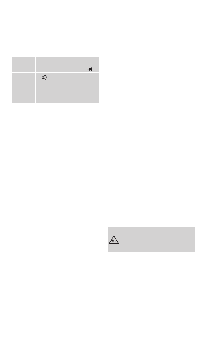
Resistance (R)
≤100Ω
-
200Ω
≤1kΩ ≤10kΩ
>10kΩ
≤100kΩ
Buzzer
1
LED100Ω ●1.●↓
2
LED1kΩ ● ● 2.●↓
3
LED10kΩ ● ● ● 3.●↓
- To determine the conducting direction of a diode,
apply the black (-) test probe 8to the cathode
and the red (+) test probe 7to the anode of the
diode. The conducting direction has been deter-
mined as soon as the yellow LEDs 1, 2and 3
light up (running light).
- If a voltage is applied to the test point, the device
warns the user of an external voltage applied by
means of the red LEDs 4and/or 5lighting up.
In this case, stop the test immediately and ensure
the absence of voltage!
Setting the buzzer volume
The buzzer volume can be set in four steps. Step 1
(low), step 2 (medium), step 3 (high) and step 4 (very
high). In step 5, the buzzer is OFF and the LED torch
is ON.
To set the volume, short-circuit the test probes 7and
8and press and hold the push-button until the
desired volume is set. The buzzer volume set remains
stored until it is changed the next time.
5. External-voltage and polarity indication
- Apply BOTH test probes 7and 8to the system
parts to be tested.
- The LEDs 4and 5for external-voltage indica-
tion detect DC ( ) and AC voltages () within a
range from 6 to 400 V.
- AC voltages () are displayed by the (+) LED 4
and the (-) LED 5lighting up simultaneously.
- DC voltages ( ) are displayed by the (+) LED
4or the (-) LED 5lighting up. The (+) LED 4
lights up, if the positive pole of the voltage source
is applied to the red (+) test probe 7and the neg-
ative pole of the voltage source is applied to the
black (-) test probe 8.
Attention!
The external-voltage indication does not replace a
two-pole voltage tester for determining the absence of
voltage.
Additional indication for external-voltage detection
(two-pole)
If the buzzer is switched on during the continuity test,
a pulsating acoustic signal warns of an external vol-
tage applied. If the buzzer is switched off during the
continuity test, the LED torch will flash as soon as
an external voltage is applied. The additional indica-
tion (pulsating acoustic signal or flashing LED torch
) can be deactivated. For this, apply the two test
probes 7and 8to a voltage source (6 V to 400 V)
and press the push-button for approx. 1 second. To
activate the additional indication (pulsating acoustic
signal or flashing LED torch ), repeat this procedure.
6. Single-pole external conductor test (phase)
- Apply the black (-) test probe 8OR the red (+)
test probe 7to the system part to be tested.
During the single-pole external conductor test
(phase), make absolutely sure not to touch the
bare testing electrode 6 of the other test probe
and make sure that it remains contactless.
- If the red LED 4flashes, the external conductor
(phase) of an AC voltage is applied to this system
part.
Additional indication for external conductor test
If required, an additional indication (pulsating acoustic
signal or flashing LED torch ) can be activated for
the external conductor test. To activate the additional
indication, connect the black (-) test probe 8OR the
red (+) test probe 7to the external conductor (phase)
of a socket and press the push-button for approx. 1
second. To deactivate the additional indication, press
the push-button once again. The additional indica-
tion (pulsating acoustic signal or flashing LED torch
) depends on the buzzer volume set for the continu-
ity test (see chapter 4).
Note:
The single-pole external conductor test (phase) can be
carried out in an earthed mains from 230 V, 50 Hz /
60 Hz (phase to earth) on.
7. Cable break detector
- The cable break detector is intended for the
non-contact localization of cable breaks on
exposed live lines.
- Pass the detector over a live line (e.g. a cable
reel or a chain of lights) from the feeding point
(phase) in direction of other end of the line.
- As long as the line is not interrupted, the red LED
4is flashing.
- The point of the cable break has been localized as
soon as the red LED 4goes out.
Additional indication for cable break detector
An additional indication (pulsating acoustic signal or
flashing LED torch ) activated for the single-pole
external conductor test (see chapter 6) is also activa-
ted for the cable break detector.
Note:
The cable break detector can be used in earthed
mains from 230 V, 50 Hz/ 60 Hz (phase to earth) on.
8. LED torch
Warning!
Potentially dangerous optical radiation!
Do not look directly or indirectly via
reflecting surfaces into the LED beam!
Danger to your retina!
- The device is provided with a high-power LED
torch with can be switched on and off by press-
ing the push-button .
- It is switched off automatically after approx. 2 min-
utes.
Setting the luminosity
The luminosity of the LED torch can be set in four
steps.
Step 1 (25 %), step 2 (50 %), step 3 (75 %) and step
4 (100 %). To set the luminosity, press and hold the
push-button until the desired luminosity is set. The
highest step 4 (100 %) will be confirmed by means of
an acoustic signal. The luminosity set remains stored
until it is changed the next time.
9. Battery replacement
- Do not apply voltage to the device when the bat-
tery compartment is open!
- The battery compartment is located on the back of
the device.
- Slightly press down the catch by means of a
09/ 2014
DUTEST
®
pro
6
 
screwdriver and push off the battery compartment
cover in downward direction at the same time.
- Replace the exhausted batteries by three new
ones of type AA (LR06). Make sure that the new
batteries are inserted with correct polarity!
- Push the battery compartment cover back onto
the housing until the catch locks into place with
an audible click.
Note:
The battery compartment cover is provided with an
integrated magnet and a belt clip for attachment of the
device.
10. Technical data:
- Built and tested according to: DIN EN 61010-1
and -031, IEC 61010-1 and -031, DIN EN 62471
- Protection against external voltages: max.
400 V, 50 Hz / 60 Hz
- Measuring category: CAT III 300 V to earth
- Continuity test:
acoustically by means of buzzer for measuring
resistancesR≤100Ωto200Ω
visually by means of three LED steps:
LED100ΩformeasuringresistancesR≤100Ω
to200Ω
LED1kΩformeasuringresistancesR≤1kΩ
LED10kΩformeasuringresistancesR≤10kΩ
- Range of tolerance: ± 20 % of the maximum value
of the LED step
- Buzzer volume: step 1 (low), step 2 (medium),
step 3 (high) and step 4 (buzzer: OFF, LED torch:
ON).
- Open-circuitvoltage:≤4.5V
- Testingcurrent:≤30µA
- Diodetest:~1.5V,max.30µA
- External-voltage detection: 6 V - 400 V AC / DC,
50 Hz / 60 Hz
- Internalresistance:166kΩ
- Current consumption: Is< 3.5 mA (400 V)
- Polarity indication: from ± 6 V on
- External conductor test (phase): Un≥230V,50Hz
/ 60 Hz
- Cable break detector: Un≥230V,50Hz/60Hz
- Contamination level: 2
- Protection category: IP 40 (DIN VDE 0470-1 IEC /
EN 60529)
4 – first index: protection against access to dan-
gerous parts and protection against solid impuri-
ties of a diameter > 1.0 mm
0 – second index: no protection against water
- Battery: 3 x 1.5 V batteries of type AA (LR06)
- Weight: approx. 130 g
- Measuring line with test handles: approx.
1,000 mm
- Operating temperature range: - 15 °C to + 55 °C
- Storage temperature range: - 15 °C to + 55 °C
- Relative air humidity: 20 % to 80 %
- Luminosity of the LED torch:
step 1 (25 %), step 2 (50 %), step 3 (75 %), step 4
(100 %)
11. General maintenance
Clean the exterior of the device with a clean dry cloth.
If there is contamination or deposits in the area of the
battery or the battery housing, clean these areas as
well by means of a dry cloth.
If the device is stored for a longer period of time,
remove the batteries from the device!
12. Environmental protection
At the end of product life, dispose of the
unserviceable device as well as used batte-
ries via appropriate collecting facilities provi-
ded in your community.
Benning Elektrotechnik & Elektronik GmbH & Co. KG
Münsterstraße 135 - 137
D - 46397 Bocholt
Phone: +49 (0) 2871- 93 - 0 • Fax: +49 (0) 2871- 93 - 429
www.benning.de • E-Mail: [email protected]

Other manuals for DUTEST pro

1

Other Benning Test Equipment manuals

Benning IT 100 User manual

Benning

Benning IT 100 User manual

Benning PV 1-1 Manual

Benning

Benning PV 1-1 Manual

Benning CM 7 Operating and installation instructions

Benning

Benning CM 7 Operating and installation instructions

Benning Z-TESTER User manual

Benning

Benning Z-TESTER User manual

Benning PV 1-1 User manual

Benning

Benning PV 1-1 User manual

Benning TRITEST easy User manual

Benning

Benning TRITEST easy User manual

Benning PV 1-1+ Manual

Benning

Benning PV 1-1+ Manual

Benning PV 2 User manual

Benning

Benning PV 2 User manual

Benning duspol expert User manual

Benning

Benning duspol expert User manual

Benning IT 105 User manual

Benning

Benning IT 105 User manual

Benning TRITEST easy User manual

Benning

Benning TRITEST easy User manual

Benning IT 110 User manual

Benning

Benning IT 110 User manual

Benning DUSPOL combi User manual

Benning

Benning DUSPOL combi User manual

Benning IT 115 User manual

Benning

Benning IT 115 User manual

Benning PROFIPOL User manual

Benning

Benning PROFIPOL User manual

Benning IT 130 Manual

Benning

Benning IT 130 Manual

Benning IT 115 User manual

Benning

Benning IT 115 User manual

Benning DUSPOL compact User manual

Benning

Benning DUSPOL compact User manual

Benning IT 130 Manual

Benning

Benning IT 130 Manual

Benning ST 725 Instruction manual

Benning

Benning ST 725 Instruction manual

Benning IT 105 CH User manual

Benning

Benning IT 105 CH User manual

Benning IT 130 User manual

Benning

Benning IT 130 User manual

Benning ST 755 User manual

Benning

Benning ST 755 User manual

Benning ST 710 User manual

Benning

Benning ST 710 User manual

Popular Test Equipment manuals by other brands

Fluke Calibration P3000 Series user manual

Fluke Calibration

Fluke Calibration P3000 Series user manual

Hanna Instruments Checker HI772 Quick reference guide

Hanna Instruments

Hanna Instruments Checker HI772 Quick reference guide

Hantek IDSO quick guide

Hantek

Hantek IDSO quick guide

Tenma 72-3565 manual

Tenma

Tenma 72-3565 manual

Dymond RS Milzar Prestige II Series owner's manual

Dymond

Dymond RS Milzar Prestige II Series owner's manual

Fluke 9040 Supplement

Fluke

Fluke 9040 Supplement

Datex-Ohmeda S/5 M-CAiOVX Technical Reference Manual Slot

Datex-Ohmeda

Datex-Ohmeda S/5 M-CAiOVX Technical Reference Manual Slot

Slaughter 2925 Operation and service manual

Slaughter

Slaughter 2925 Operation and service manual

Gilson MC-250CS operating manual

Gilson

Gilson MC-250CS operating manual

Cole Parmer HBC-300 Series instruction manual

Cole Parmer

Cole Parmer HBC-300 Series instruction manual

Scheppach MFVT01 Instructions for use

Scheppach

Scheppach MFVT01 Instructions for use

Hanwei AT8900 Operation manual

Hanwei

Hanwei AT8900 Operation manual

METREL SwiftPAT MI 3302 instruction manual

METREL

METREL SwiftPAT MI 3302 instruction manual

Amprobe AM-42 user manual

Amprobe

Amprobe AM-42 user manual

palintest SKW 400 Operation manual

palintest

palintest SKW 400 Operation manual

JDS Uniphase TestifierPRO user guide

JDS Uniphase

JDS Uniphase TestifierPRO user guide

TEXIO DCS-2000E SERIES Programming manual

TEXIO

TEXIO DCS-2000E SERIES Programming manual

Tektronix MSO3000 Series user manual

Tektronix

Tektronix MSO3000 Series user manual

manuals.online logo
manuals.online logoBrands
  • About & Mission
  • Contact us
  • Privacy Policy
  • Terms and Conditions

Copyright 2025 Manuals.Online. All Rights Reserved.