Cliftech Design V-Gauge Lite User manual

© 2008 Cliftech Design
V-Gauge Lite
A pocket gauge
for the
Harley-Davidson V-Rod
Introduction
Have you every wondered:
●How hot is my engine (coolant temperature)?
●What was the highest temperature reached?
●Why are the fans on (or off)?
●What is the average fuel economy (mpg)?
●How does the instantaneous mpg depend on speed, wind, RPM, riding position, etc.?
●Did my last performance modification affect fuel economy?
●How many gallons of fuel are really left?
●How accurate is my stock fuel gauge?
●How many seconds from 0 to 60mph?
●What are my 60', 330', 1/8, and 1/4 mile times?
●At what RPM am I really shifting?
●What was my maximum speed?
The V-Gauge Lite is an electronic instrument specifically designed for the Harley-Davidson
V-Rod. The concept of the gauge is simple: use a 3-wire hook-up (ground, 12V, and digital bus)
to listen to the data running across the serial data bus. It comes with a pre-installed connector
ready to plug straight into the computer diagnostic port on your bike. Its compact size means
that it can be easily carried in your tool pouch or a jacket pocket. A small Velcro attachment
allows it to be quickly installed in any visible location on the front of your V-Rod all the time or
just when you need it.

1130CC.COM / 1250CC.COM 2
V-Gauge Lite Manual V1.2 © 2008 Cliftech Design
Contents
Introduction ..................................................................................................... 1
1. Specifications ................................................................................................... 3
2. Button controls ................................................................................................. 4
3. Normal Operation .............................................................................................. 4
Start-up screen ............................................................................................. 4
Shift point adjustment and odometer .................................................................. 4
Run screens.................................................................................................. 5
RPM graphical screen ...................................................................................... 5
Digital RPM screen ......................................................................................... 6
Temperature screen ....................................................................................... 7
Trip odometer screen...................................................................................... 7
Fuel economy screen ...................................................................................... 7
4. Drag race timing ................................................................................................ 9
Timing data screens....................................................................................... 10
Maximum speed screen................................................................................... 11
RPM shift point screen.................................................................................... 12
Drag timing reset “READY” screen ..................................................................... 12
5. User calibration................................................................................................ 14
Entering the user calibration mode and making adjustments ..................................... 14
Serial number screen ..................................................................................... 15
Units adjustment mode .................................................................................. 15
Gear calibration mode.................................................................................... 17
Speed calibration mode .................................................................................. 18
Fuel calibration mode .................................................................................... 19
6. V-Gauge Lite installation..................................................................................... 21
Wiring the gauge .......................................................................................... 21
Mounting the gauge ....................................................................................... 22
Sunlight visibility .......................................................................................... 23
Weather resistance ....................................................................................... 23
7. Complete screen navigation map ........................................................................... 24
1130CC.COM / 1250CC.COM 3
V-Gauge Lite Manual V1.2 © 2008 Cliftech Design
1. Specifications
The functionality provided by the V-Gauge Lite can be summarized as follows:
●Metric, US, or UK units
●Gear position indicator, N-5 while clutch is engaged (lever out)
●Programmable shift indicator (0-12,000 RPM)
●Digital speed (0-158mph, 0-255kph)
●Digital RPM (0-12,000), also available as a moving bar display
●Coolant temperature (F or C)
●Maximum coolant temperature since last reset (F or C)
●Trip odometer (0-2500mi, 0-4000km)
●Fuel used (0-200gal US, 0-160gal UK, 0-800L)
●Instantaneous fuel economy (mpg or kpL)
●Average fuel economy since last trip meter reset (mpg or kpL)
●Standard odometer (0-999,999mi, 0-999,999km)
●Drag timing functions
– 60’, 330’, 1/8mi, and 1/4mi speed, time (1/10s), and gear position
– 0-60mph time (1/10s)
– Maximum speed
– RPM shift points 1-2, 2-3, 3-4, and 4-5
●Adjustable speed calibration in %
●Adjustable fuel use calibration in %
●Adjustable pulley calibration (1-255 teeth, 26-30 typical)
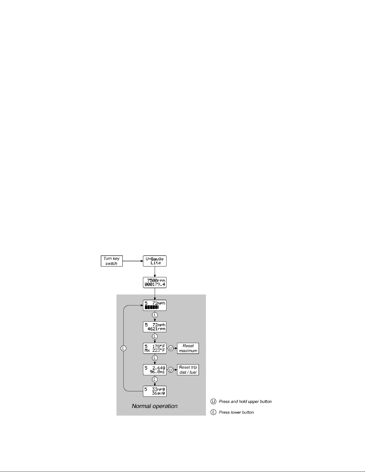
Figure 1 – Screen map of the normal operation of the V-Gauge Lite.

1130CC.COM / 1250CC.COM 4
V-Gauge Lite Manual V1.2 © 2008 Cliftech Design
2. Button controls
There are two buttons on the left side of the gauge front. These are referred to as the “upper”
and “lower” buttons. The lower button always has the function of switching between different
screen displays within a given mode. The upper button is used to switch between modes or to
reset the data for a display screen. The bottom button works immediately. The top button
always needs to be pressed and held for at least 2 seconds.
3. Normal Operation
Figure 1 shows a map of the normal operation functions. It might at first look complicated but
stop and look again. It is really very simple. There are only 5 basic run screens, a trip
odometer reset function, and a maximum temperature reset function. The following section
describes these in more detail.
Start-up screen
When the V-Gauge Lite is first powered on by turning the bike’s key switch, a start-up screen is
displayed. This screen is shown in Figure 2. After the 1130CC.COM intro, this screen is
displayed for 3 seconds and then automatically switches to the shift point/odometer screen.
Figure 2 – Introduction screen shown for 3 seconds after power up. A small screwdriver can be used to
adjust the screen contrast through the opening on the right.
Shift point adjustment and odometer
As long as the V-Rod ignition key is in the on position and the engine off/run switch (right
handlebar control) is in the off position, the RPM adjustment screen is displayed. In this screen,
the lower button decreases the RPM at which the shift indicator is activated (in steps of 10) and
the upper button increases the RPM. As shown in Figure 3, the odometer is also displayed at
the bottom of this screen. This is the permanent, non-resetable odometer as opposed to the
trip odometer that will be described later in this section.

1130CC.COM / 1250CC.COM 5
V-Gauge Lite Manual V1.2 © 2008 Cliftech Design
Figure 3 – Shift point adjustment screen and odometer. This screen is displayed until the ignition switch
(right handlebar control) is turned on. The upper and lower buttons adjust the RPM set point.
Run screens
When the engine off/run switch (right handlebar control) is set to run, the RPM shift point
screen is automatically replaced with the last run screen that was selected when the bike was
powered down. If you would like to exit the RPM/odometer screen without turning on the
ignition, then simultaneously pressing both the upper and lower buttons will accomplish this.
Pressing the lower button will cycle the display between the 5 available run screens as shown in
Figure 1. These 5 screens are described in more detail as follows.
RPM graphical screen
The first run screen, shown in Figure 4, is the simplest and provides easy readability for routine
use. The gear position is shown in the top left of all 5 of the run screens. Remember that this
only reads correctly when the clutch is engaged (lever released). The speed is shown just to
the right of the gear position. On the second line is a horizontal bar that graphically displays
the RPM. The full right hand extension of this bar corresponds to the shift point that was set as
described previously. In other words, when the bar completely fills the lower line of the
display, the shift point has been reached.
When the programmable shift point is reached, the entire display is filled with black characters
as shown in Figure 5. Note that this occurs no matter which of the 5 run screens is currently
displayed. While this is a very poor substitute for a specially designed shift light (such as that
on the full-function V-Gauge), it can still be helpful in tuning the optimal shift RPM.
REMEMBER
The gear position is calculated from the ratio of bike speed and engine RPM. For
this reason, it only reads correctly when the clutch is engaged
(lever released).

1130CC.COM / 1250CC.COM 6
V-Gauge Lite Manual V1.2 © 2008 Cliftech Design
Figure 4 – First run screen displaying the gear position, speed, and RPM. The horizontal bar at the
bottom of the screen graphically displays the RPM. A full scale reading corresponds to the adjustable
shift point that was programmed as shown in Figure 3.
Figure 5 – When the shift point is reached, the entire display is filled with black characters. This
happens in any of the 5 run screens.
Digital RPM screen
The second run screen, shown in Figure 6, is similar to the graphical screen except that the RPM
bar chart on the lower line is replaced with the digital RPM.
Figure 6 – The RPM bar chart is replaced with the digital RPM in the second run screen.
1130CC.COM / 1250CC.COM 7
V-Gauge Lite Manual V1.2 © 2008 Cliftech Design
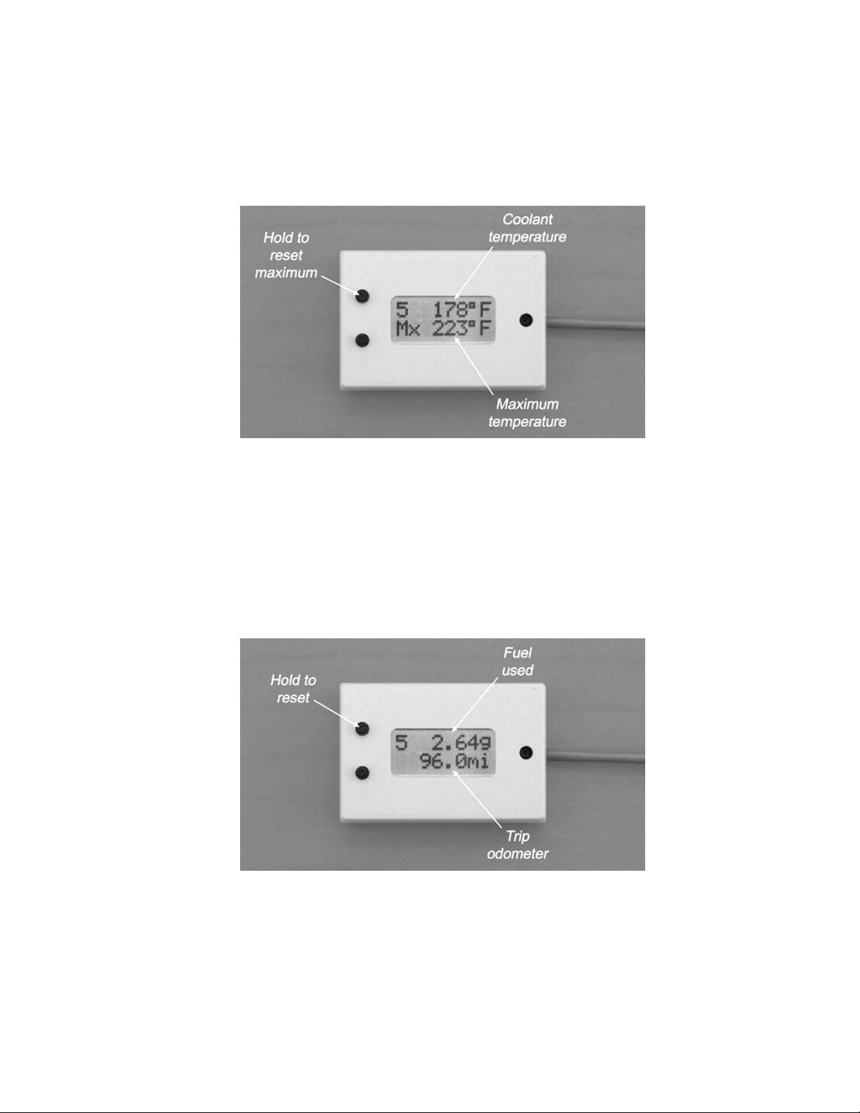
Temperature screen
The temperature screen, shown in Figure 7, reports the current coolant system temperature on
the top display line. The maximum temperature reached is shown on the second line. The
maximum recorded temperature will be remembered (even after power-down) until it is reset
by pressing and holding the upper button while the temperature screen is displayed.
Figure 7 – The temperature screen displays the current coolant temperature and the maximum
temperature reached since the last reset. The maximum can be reset by pressing and holding the upper
button.
Trip odometer screen
The trip odometer screen, shown in Figure 8, displays the distance traveled and the amount of
fuel used since the last reset. Both of these values are simultaneously reset by pressing and
holding the upper button. It is often useful to reset the trip odometer at each fuel-up. The
fuel used can then be compared to the known tank capacity.
Figure 8 – The fuel used and distance traveled are shown on the trip odometer screen. Both of these
values are reset by pressing and holding the upper button.
Fuel economy screen
The last of the 5 run screens is the fuel economy screen, shown in Figure 9. The instantaneous
fuel economy is shown on the top line of the display and is updated approximately twice per
second. The lower line is the average fuel economy since the trip odometer was last reset (see

1130CC.COM / 1250CC.COM 8
V-Gauge Lite Manual V1.2 © 2008 Cliftech Design
previous section). The instantaneous fuel economy reading is very valuable in showing the
effect of speed, wind, riding position, etc. on the amount of fuel used.
Figure 9 – The fuel economy screen showing both the instantaneous (live) and average fuel economy.
The average value is reset by clearing the trip odometer (see previous section).

1130CC.COM / 1250CC.COM 9
V-Gauge Lite Manual V1.2 © 2008 Cliftech Design
4. Drag race timing
The V-Gauge Lite provides a system for measuring motorcycle performance by timing 60ft, 330ft
(1/16mi), 1/8mi, and 1/4mi distances. It also records the speed and gear position for each.
The 0-60mph time as well as the actual RPM shift points are also automatically recorded. The
times are measured in 1/10 second increments since the V-Rod ECM reports about 12 speed
readings per second.
CAUTION!
The drag race timing function should never be used on public roadways. For
your own safety and the safety of others, never exceed the posted speed limit.
The V-Gauge Lite is no substitute for a track timing system but it can be a handy tool for
measuring the effect of modifications on the bike’s performance. Remember that, since the
speedometer pulse sensor is in the transmission (not on the front wheel, for example), rear tire
spin will cause incorrect distance readings. Also, the accuracy of the drag measurements is only
as good as the speedometer calibration.
Figure 10 – Screen map showing the added functionality of the drag timing functions.
1130CC.COM / 1250CC.COM 10
V-Gauge Lite Manual V1.2 © 2008 Cliftech Design
Figure 10 shows a map of the V-Gauge Lite functions to which the drag timing screens have
been added. To enter the drag timing mode, hold the upper button for at least 2 seconds from
the RPM graphical screen shown in Figure 4. The bike must be stopped. This will switch the V-
Gauge Lite to the drag data review screens, allowing you to see the measurements from the last
run.
As usual, the lower button advances the display through the available screens. Holding the
upper button for at least 2 seconds in any one of the drag data screens resets the drag timer
and brings up the “READY” screen to time a new run. The drag data can only be reviewed while
the bike is stopped. As soon as the bike starts rolling, the display is returned to the RPM
graphical screen.
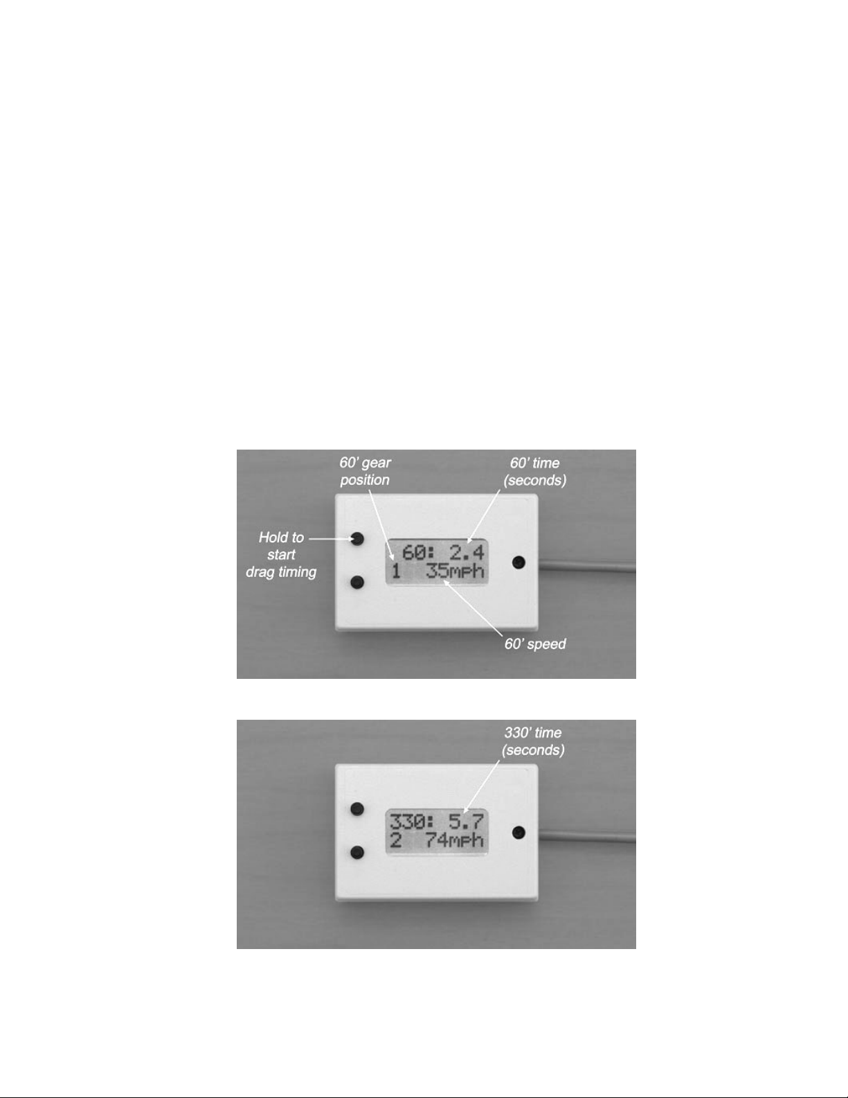
Timing data screens
The first 4 data screens show the measured times for the 60ft, 330ft, 1/8mi, and 1/4mi
distances. Figures 11-14 shows each of these screens. In each case, the time (1/10s) is shown
at the end of the first display line and the recorded gear position for that distance is shown at
the beginning of the second line. The speed is at the end of the second line, to the right of the
gear position.
Figure 11 – First drag timing data screen (60 feet).
Figure 12 – Second drag timing data screen (330 feet, 1/16 mile).
1130CC.COM / 1250CC.COM 11
V-Gauge Lite Manual V1.2 © 2008 Cliftech Design
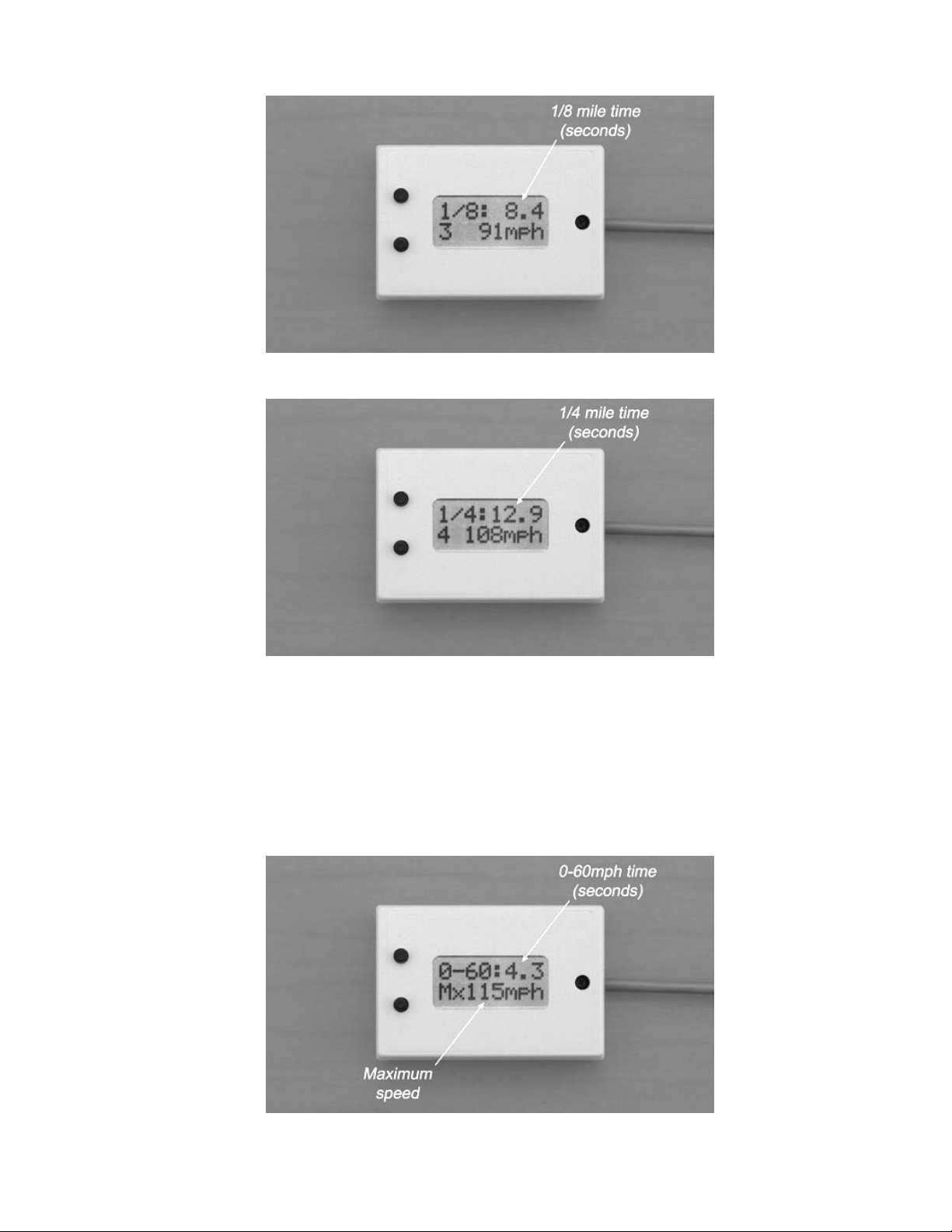
Figure 13 – Third drag timing data screen (1/8 mile).
Figure 14 – Fourth drag timing data screen (1/4 mile).
Maximum speed screen
The fifth drag data screen, shown in Figure 15, displays the time for 0-60mph on the top line
and the maximum speed reached during the run on the second line. The speed will be recorded
even if it occurs after the ¼ mile distance has been reached since the motorcycle is generally
still accelerating at the end of the run. Note that 0-60mph times greater than 9.9s will not be
displayed correctly. This should never be a problem with the V-Rod!
Figure 15 – Maximum speed screen.

1130CC.COM / 1250CC.COM 12
V-Gauge Lite Manual V1.2 © 2008 Cliftech Design
RPM shift point screen
The last two drag race data screens, shown in Figures 16-17, show the actual recorded RPM for
each of the shift points. The first screen shows the 1-2 and 2-3 shift RPMs and the second
screen shows the 3-4 and 4-5 shift RPMs.
Figure 16 – First RPM shift point screen.
Figure 17 – Second RPM shift point screen.
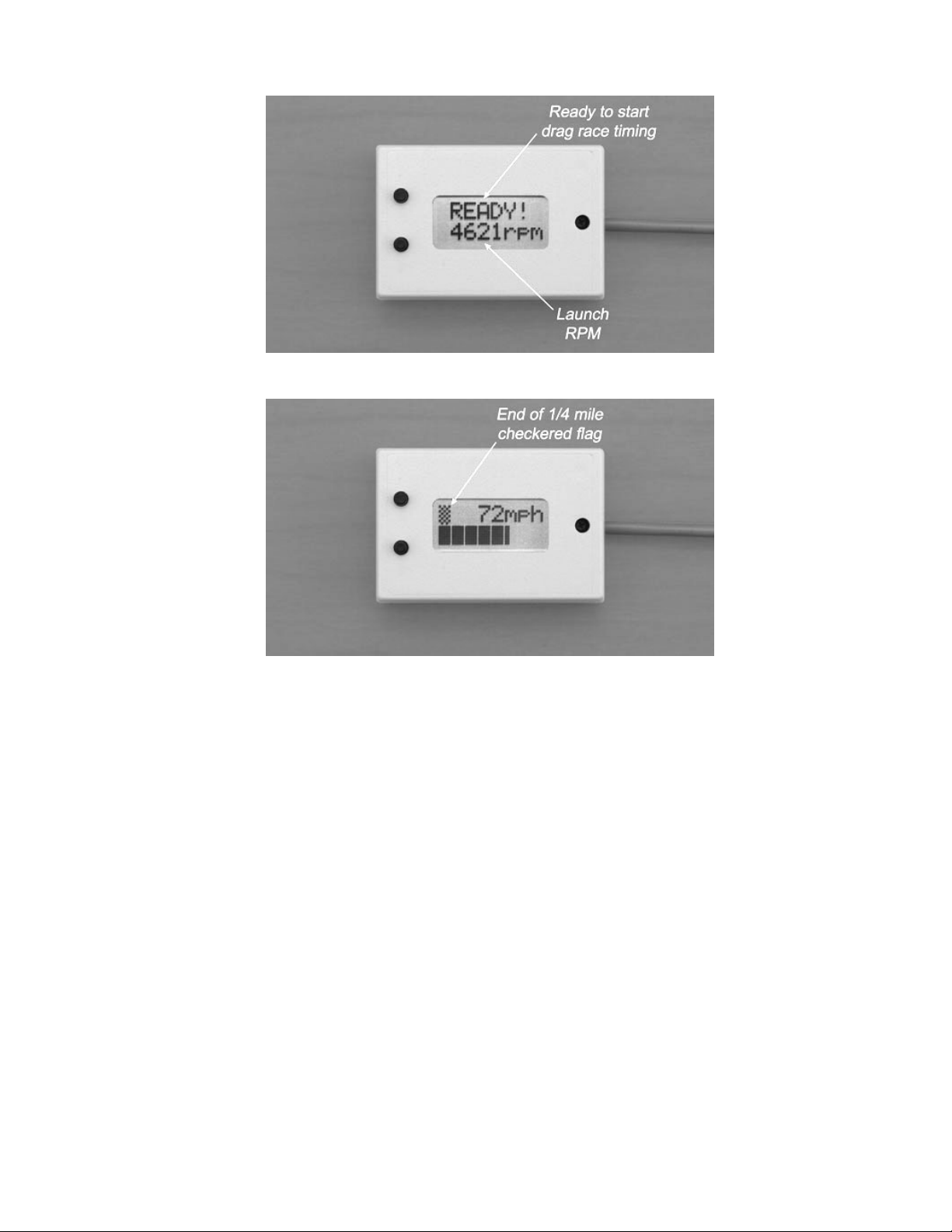
Drag timing reset “READY” screen
A new drag timing run can be started from any one of the 7 drag data screens. Simply press and
hold the upper button (at least 2 seconds) until the “READY” screen, shown in Figure 18, is
displayed. The second line of the display shows the digital RPM so the engine can be revved to
a chosen RPM before dropping the clutch. Again, the bike must be stopped and timing
automatically starts as soon as the bike moves. Once started, the display returns to the RPM
graphical screen shown in Figure 4. When a 1/4 mile has been covered, the gear position read-
out is replaced with a small checkered flag, as shown in Figure 18, to indicate that the run is
complete.
1130CC.COM / 1250CC.COM 13
V-Gauge Lite Manual V1.2 © 2008 Cliftech Design
Figure 18 – The drag timing “ready to start” screen.
Figure 19 – The gear position read out is replaced by a small checkered flag character to indicate the
end of a ¼ mile run. The flag character remains in place for all display screens until the drag data is
reviewed.
The bike has to be stopped to review the data from the run. As previously described, holding
the upper button for at least 2 seconds from the RPM graphical screen brings up the drag timing
data. The data from the run is retained in the V-Gauge Lite, even after it is powered down,
until a new run is recorded. Note, however, that the data is not stored until it is reviewed for
the first time. If the V-Gauge Lite is powered down before looking at the data from a run, it
will be lost and the data from the previously stored run will be retained.

1130CC.COM / 1250CC.COM 14
V-Gauge Lite Manual V1.2 © 2008 Cliftech Design
5. User calibration
The V-Gauge Lite does not directly measure the speed and the amount of fuel used but uses the
values reported by the V-Rod’s computer control system (ECM). So, why may calibration be
needed? There are a number of variables that could affect the accuracy of the reported values
including gear ratio and tire size. There are provisions for calibrating the speed and the fuel
use as well as for compensating for different size secondary drive pulleys. For the gear position
indicator to work correctly, the number of teeth on the drive pulley must be entered. If the
Harley-Davidson computer download has not been done for a new drive pulley or if the stock
tire size has been changed, then a speed calibration must also be made. The user calibration
also allows the units to be switched between metric and English units.
Figure 20 – Map of the user calibration screens. User calibration is started by holding the upper button
while powering up the V-Gauge Lite.
Entering the user calibration mode and making adjustments
The user calibration can be a one time operation. The calibration factors are stored in non-
volatile memory and, once correct, should never need to be changed. The user calibration
mode is entered by holding the upper button while powering up the V-Gauge Lite. As shown in
the Figure 20 map, there are 4 calibration screens and a serial number screen. In each of the
calibration screens, the upper and lower buttons are used to adjust the values. Pressing both
buttons at the same time advances to the next screen. Take care to press the buttons
simultaneously to avoid accidentally making an unwanted change as you leave each screen.
Figure 21 – The serial number screen. Note: the current firmware is V1.2
1130CC.COM / 1250CC.COM 15
V-Gauge Lite Manual V1.2 © 2008 Cliftech Design
Serial number screen
When the upper button is held down during start-up for at least 4 seconds, the serial number of
the unit as well as the version of the firmware (internal software) is displayed, as shown in
Figure 21, until the button is released.
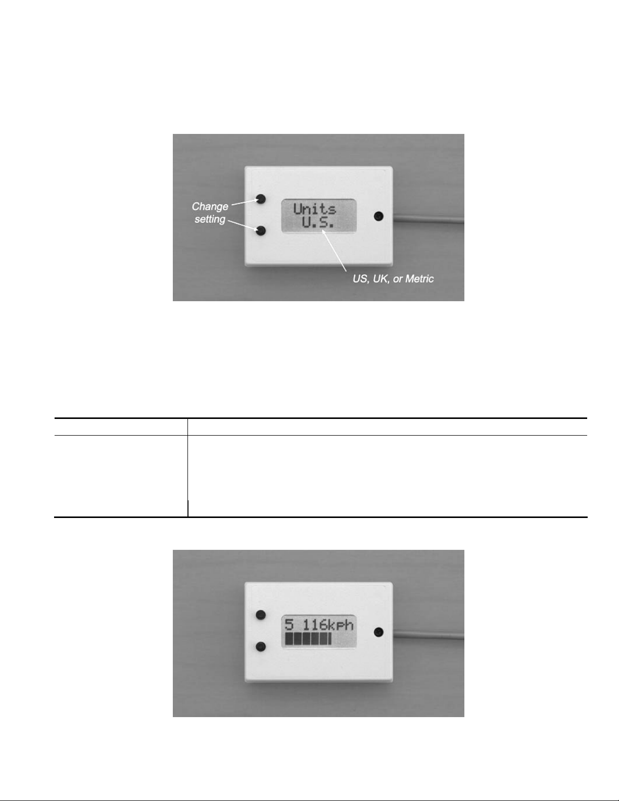
Figure 22 – The units adjustment screen.
Units adjustment mode
The first user calibration screen is the units selection screen shown in Figure 22. The units can
be switched between US, UK, and metric modes. After setting the mode, pressing both buttons
at the same time advances to the gear calibration screen. Table I summarizes the units
displayed for each of these modes.
Measurement U.S. U.K. Metric
Distance Miles (mi) Miles (mi) Kilometers (km)
Speed Miles/hour (mph) Miles/hour (mph) Kilometers/hour (kph)
Fuel volume Gallons (g) Imperial gallons (g) Liters (L)
Fuel economy Miles/gallon (mpg) Miles/gallon (mpg) Kilometers/liter (kpL)
Temperature Fahrenheit (oF) Celsius (oC) Celsius (oC)
Table I – Summary of the three unit display modes.
Figure 23 – The RPM graphical screen in metric units mode (compare to Figure 4).

1130CC.COM / 1250CC.COM 16
V-Gauge Lite Manual V1.2 © 2008 Cliftech Design
Figure 24 – The digital RPM screen in metric units mode (compare to Figure 6).
Figure 25 – The coolant temperature screen in metric units mode (compare to Figure 7).
Figure 26 – The trip odometer and fuel usage screen in metric units mode (compare to Figure 8).
1130CC.COM / 1250CC.COM 17
V-Gauge Lite Manual V1.2 © 2008 Cliftech Design
Figure 27 – The fuel economy screen in metric units mode (compare to Figure 9).
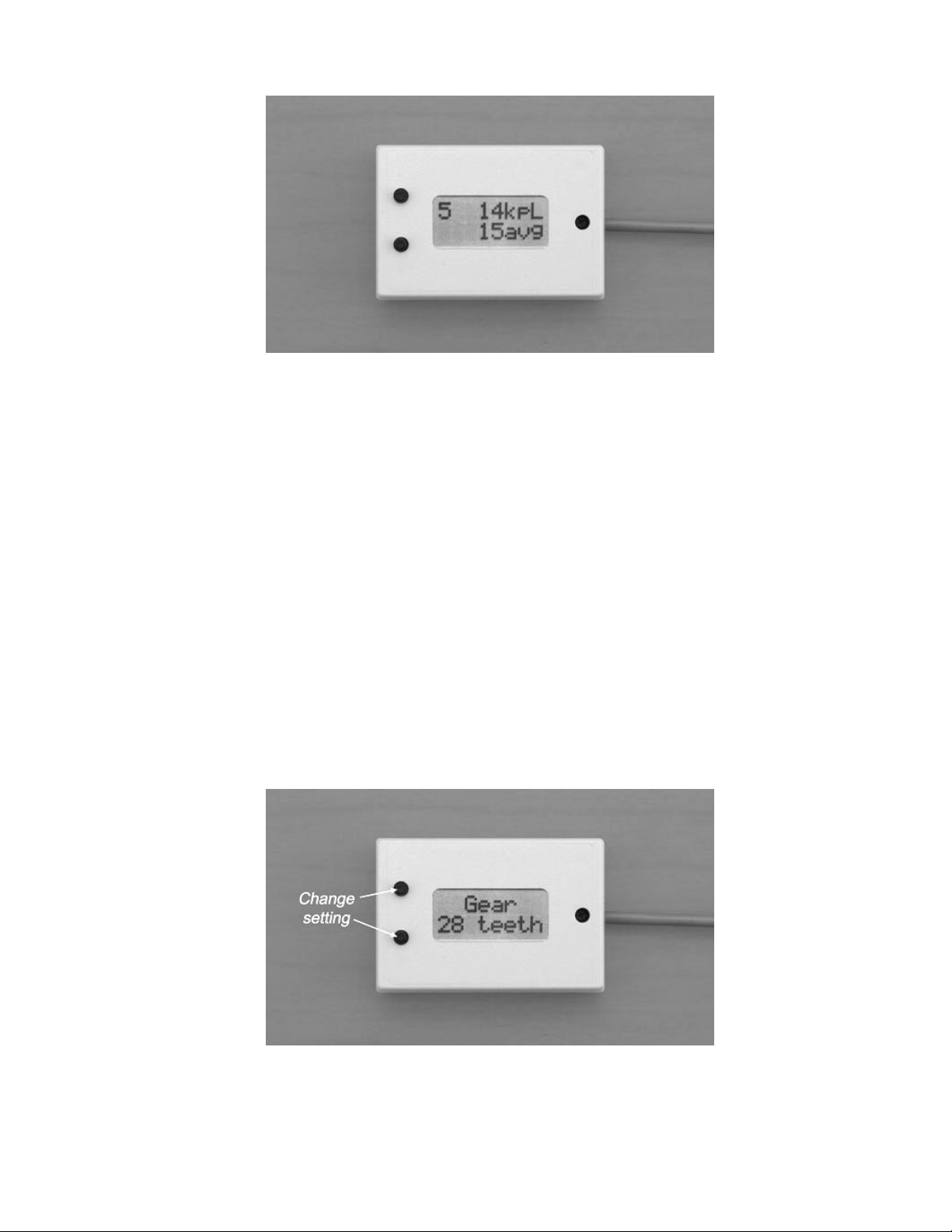
Gear calibration mode
There are several different commonly used secondary drive pulleys on the V-Rod ranging from
26 to 30 teeth. The gear calibration screen, shown in Figure 18, allows the number of teeth to
be adjusted from 1 to 255. This value must be correctly entered in order for the V-Gauge Lite
gear position display to be correct. The value entered needs to match what is currently
programmed into the ECM and may not necessarily match the actual pulley installed on the
motorcycle. The ECM may still have the factory installed download (which will match the
original drive pulley delivered) or may have been reprogrammed with a download from a
dealership or modified using a race tuner. The value that needs to be entered must match
what your bike’s ECM thinks is installed, not what might actually be there. For example, in the
U.S., 2002-2003 V-Rods came with 30 tooth pulleys (30T). 2004 and beyond have the 28T.
Later European models generally kept the 30T.
Note that the pulley calibration value has no effect on the speed calibration discussed in the
following section. If the rider has changed the secondary drive pulley without an ECM flash (or
race tuner adjustment), then the speed calibration will also need to be corrected for accurate
speedometer readout and race timing functions.
Figure 28 – The gear calibration screen.
After setting the number of teeth, press both buttons at the same time to advance to the speed
calibration screen.
1130CC.COM / 1250CC.COM 18
V-Gauge Lite Manual V1.2 © 2008 Cliftech Design
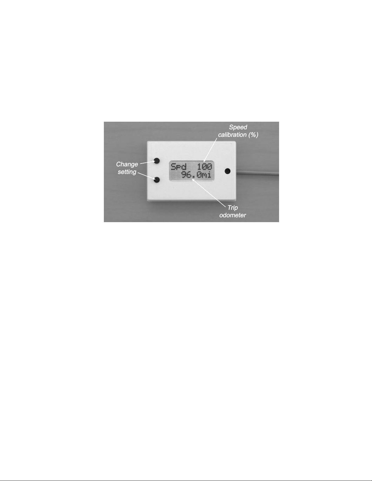
Speed calibration mode
The speed calibration factor is adjustable between 1 and 255%. The nominal setting of 100%
will give the correct reading for a bike that has been correctly flashed with the current drive
pulley size. If not, the calibration can be easily adjusted. Even with an updated ECM flash, you
may want to fine tune the calibration to further improve the speedometer accuracy. An
example of the need for this would be if you are running a slightly different tire size from stock.
There are two methods to calibrate the speedometer reading. One uses the speed readout and
the other uses the trip odometer. These are described in more detail as follows.
Figure 29 – The speed calibration screen. Note that the trip odometer (compare to Figure 8) is also
shown with the speed calibration value (%).
Method #1:
1. Place the V-Gauge Lite in one of its normal operation screens that display the speed and
measure the actual speed of the bike using another reliable source. This could be done by
pacing against another vehicle or, much better, using a GPS receiver. Observe the readout
on V-Gauge Lite compared to a known accurate speed.
2. Estimate the change in calibration factor. This could be done by trial and error but the
following formula allows this to be done in one step:
New speed calibration (%) = Correct speed (GPS) ÷ Displayed speed × Current calibration (%)
3. Enter the speed calibration screen (see instructions above) and use the upper and lower
buttons to change the speed calibration to the new value (rounded to the nearest whole
number).
4. Test the correction against the speed measurement reference (GPS, etc.).
Method #2 – This method relies on the fact that the trip odometer reading is also shown on the
speed calibration screen (see Figure 29).
1. Place the V-Gauge Lite in the trip odometer screen (see Figure 8) and reset the trip
odometer by pressing and holding the upper button.

1130CC.COM / 1250CC.COM 19
V-Gauge Lite Manual V1.2 © 2008 Cliftech Design
2. Ride the bike for a precisely known distance, preferably for at least 10 miles for best
accuracy. Just as for method #1, a GPS receiver is a good way to go here although highway
markings may also work well.
3. Enter the speed calibration screen (see instructions above) and use the upper and lower
buttons to adjust the speed calibration value (%) until the trip odometer reading (shown on
the first display line) matches the correct distance ridden.
After adjusting the speed calibration, press both button at the same time to advance to the fuel
calibration screen.
Fuel calibration mode
The fuel calibration factor is adjustable between 1 and 255%. Although the nominal setting of
100% will give the theoretically correct reading, a value of 110% was found to given the best
accuracy on two tested V-Rods (’03 VRSCA, ’06 VRSCR). This is the value programmed in the V-
Gauge Lite as delivered.
Figure 30 – The fuel calibration screen. Note that the fuel usage (compare to Figure 8) is also shown
with the fuel calibration value (%).
The following procedure is used to adjust the fuel use calibration factor.
1. Fill the fuel tank as near as reasonably possible to the top of the filler neck.
2. Place the V-Gauge Lite in the fuel management screen (see Figure 8) and reset the fuel use
to zero by pressing and holding the upper button.
3. Wait until the next time the bike needs to be refueled.
4. Fill the fuel tank to as full as reasonably possible, again.
5. Enter the fuel calibration screen (see instructions above) and use the upper and lower
buttons to adjust the fuel calibration value (%) until the number of gallons shown (or liters,
in metric mode) matches as near as possible what the pump said was just dispensed into the
tank.

1130CC.COM / 1250CC.COM 20
V-Gauge Lite Manual V1.2 © 2008 Cliftech Design
After adjusting the fuel calibration, press both button at the same time to advance to the RPM
shift point screen. Once reaching this point, as shown in Figure 20, V-Gauge Lite returns to
normal operation.
IMPORTANT NOTE:
Performance add-on products such as Gil’s Box or the Power Commander intercept
the fuel injection pulses from the ECM and replace them with their own. Since the
V-Gauge Lite uses only the data that the ECM provides, installing one of these
products may affect the accuracy of the fuel consumption data. Under most riding
conditions, the one-time calibration function described here should reduce
possible errors to an acceptable level. However, the accuracy of the fuel usage
reported by the V-Gauge Lite will always be highest without after-market fuel
management systems.
Table of contents
Popular Motorcycle Accessories manuals by other brands


Kuryakyn
Kuryakyn 9931 Installation instructions manual

MadStad Engineering
MadStad Engineering Robo Knob manual

Dakota Digital
Dakota Digital MCL-3K-A manual

IBEX
IBEX 10007072 Mounting instruction

Ohlins
Ohlins Mechatronics 35007-01 Installation instruction

hepco & becker
hepco & becker 730.4527 Assembling instructions