ClimAir Multi Therm-C User manual

Operating instructions
Clock thermostat
optimising controller
Operating instructions
Clock thermostat
MTC
optimising controller
Operating instructions
Clock thermostat
optimising controller
MTC-GB v03-01

Room thermostat MTC
2/12
1Table of contents
OPERATING INSTR CTIONS 1
C
LOCK THERMOSTAT
1
1
TABLE OF CONTENTS 2
2
DESIGNATED USE 2
2.1
S
AFETY
3
3
DESCRIPTION OF THE THERMOSTAT 3
3.1
C
ONCISE SPECIFICATIONS
3
3.2
T
ECHNICAL SPECIFICATIONS
3
4
MOUNTING AND ELECTRICAL CONNECTION 3
4.1
M
OUNTING
3
4.2
E
LECTRICAL CONNECTION
4
4.3
O
NE HEATER ON ONE CONTROLLER
4
4.4
S
EVERAL UNITS ON
1
THERMOSTAT
4
5
SETTINGS 5
5.1
L
ANGUAGE
5
5.2
T
IME
/
DATE
5
5.3
T
EMPERATURES
5
5.4
C
LOCK PROGRAM
5
5.5
H
EATING PROGRAM
6
6
VENTILATION 6
7
OVERTIME TIMER 6
8
OPTIMISER 7
9
KEYBOARD LOCKING 7
10
DISPLAY 7
11
CALIBRATING THE THERMOSTAT 7
12
DESTRATIFICATION (DELAT T REGULATION) 8
13
BACK TO FACTORY DEFAULT SETTINGS 8
14
REMOTE SENSOR 8
14.1
ELECTRICAL
CONNECTION: 8
14.2
S
ETTING THE CONTROLLER FOR THE REMOTE SENSOR
9
14.3
A
VERAGE TEMPERATURES
9
14.4
E
RRORS WITH THE REMOTE SENSOR
9
15
OPTIONAL EXTERNAL INPUT 9
16
SOLVING AND ANALYSING FAILURES 9
17
OBTAINING EXTRA INFORMATION FROM THE CONNECTED HEATERS 10
18
INSTALLER MENU 11
19
INTERNAL BATTERY 11
20
MAINTENANCE AND SERVICE 12
2Designated use
The Multi Therm-C clock thermostat has been designed to control room heaters that work according
to the Argus bus system. This is a two-wire low voltage communication system. The thermostat is not
suitable to switch 24V, 230V or other signals. It may only be used in dry rooms with slight impurities
(degree of protection IP30).

Room thermostat MTC
3/12
Before use, carefully read these operating instructions and observe them. In case the mounting and
operating instructions are not observed, the manufacturer’s warranty will not apply to any resulting
damage.
2.1 Safety
Electrical devices may only be connected by a qualified electrician. Always observe the relevant
national regulations. Interferences and changes to the device will lead to cancellation of the warranty.
3 Description of the thermostat
1.Display
2.Info button to display information
3.Menu button to enter and exit the menu
4.OK button to confirm a setting
5.+ and – buttons to raise or lower settings
6.openings for the temperature sensor
3.1 Concise specifications
•Room thermostat with clock function
•Optimising controller
•Permanent display of the room temperature
•10 different programmable time blocks
•Up to 8 heaters controllable
•Frost protection
•Keyboard locking
•Overtime program
•Ventilation
•Failure diagnosis of the devices
•Suppression of interference of the heater
•Compensation for wall influence
•suited for remote sensor
•Supplied battery, excellent for preserving data in case of power failure
3.2 Technical specifications
•Power supply: low-voltage current
•Temperature range: 0-30 degrees Celsius
•Controller: PI
•Clock: 10 programmable switch blocks
•Degree of protection: IP30
4 Mounting and electrical connection
4.1 Mounting
The clock thermostat is suitable for mounting in dry, not too dusty rooms.
Place the thermostat in a room in a location where air can circulate
unimpeded. Beware that in winter the low-standing sun cannot shine directly onto the thermostat.
Placement above or near a device that radiates heat is also not recommended. Avoid placement on a
cold outdoor wall; place the thermostat on an indoor wall free of draught. All these things have an
2
4
5
6
3
5
1

Room thermostat MTC
adverse effect on the correct measurement of the room temperature and hen
operation of the thermostat.
By pressing the notch on the bottom of the thermostat, you can open the thermostat. The bottom plate
containing the connector can be mounted on a universal wall box or directly on the wall.
Be ware that the c
ontroller should not be mounted near a an
communication network. These antennas may disturb the correct functioning of the controller.
Always keep a few meters distance.
Place the thermostat in a place where you can see the
to reset a heater, the effect must be visible.
4.2 Electrical connection
In all cases the communication between the heater and the
thermostat is based on a two wire, low
the appliance the wire for
the thermostat has to be connected
to connection 4 and 5 (see also electrical wiring diagram).
Connect the thermostat wires to the connector
marked with RT
If the right connector is used the thermostat will
become defect.
Cable specification: signal ca
ble, 1x2x0,8 (shielded and twisted)
Maximum length 200m.
If the cable is chosen too thin, the signal will become too poor. If the cable is not shielded and twisted
the signal might become disturbed in an EMC unfriendly environment.
Keep the thermostat ca
ble separated from mains cables. Connect the earth shield of the cable only to
the earth terminal in the heater.
If these guidelines are not followed it may result in malfunction of the installation or worse, it could
damage the thermostat or the electron
4.3
One heater on one controller
Standard nothing needs to be changed in the heating device. In case the
thermostat does not work, check that the micro
plate in the room heater are set as shown on the right: number
and the other numbers down. The switch S3 should be set to 1. In case
several devices are connected to 1 thermostat, refer to the relevant chapter
in this manual.
This thermostat is only suitable for connection to heating devices specifically intended for this
purpose. Never connect, for example, 24V or another voltage of another system to the thermostat.
This can damage the thermostat.After making the changes insid
plug the power to the heater for the changes to become effective.
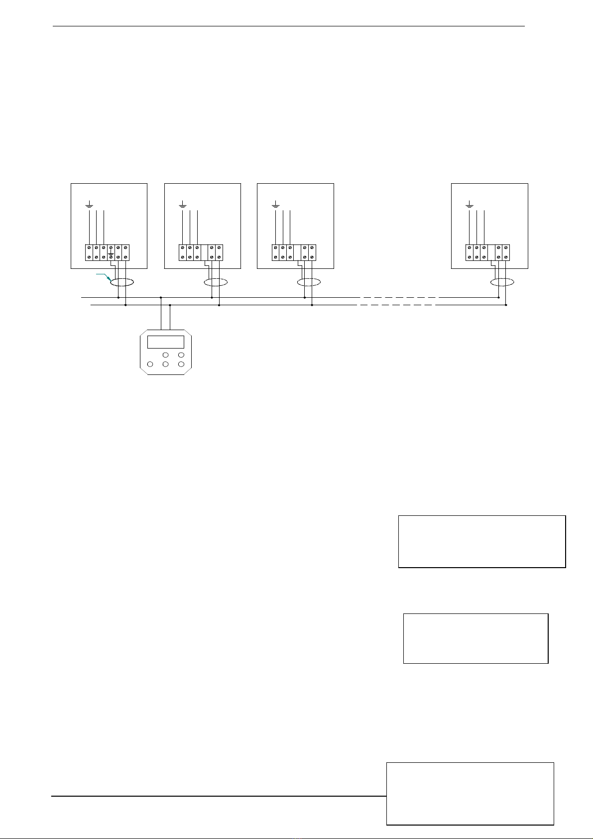
4.4
Several units on 1 thermostat
The room thermostat can control up to 8 room heaters. Connecting
them is simple, but it should be done properly.
Pay attention to the following:
•
Each unit must be given its own number (to be set with the
micro-
switch S2 in the unit).
•
One unit must have the S2 number 1 set on ON (this unit
provides for the communication) and S3 to 1, al the other
heaters should have S3 set to 0.
•
Between the separate units, the numbers 4 must be
connected with the numbers 4 and the number 5 with 5. They must not be connected in a
cross-wise manner.
The functionality of the thermostat does not change by connecting a number of room heaters.
1 2 3 4
ON
1 2 3 4
ON
1 2 3 4
ON
S2
adverse effect on the correct measurement of the room temperature and hen
By pressing the notch on the bottom of the thermostat, you can open the thermostat. The bottom plate
containing the connector can be mounted on a universal wall box or directly on the wall.
ontroller should not be mounted near a an
t
ennas from any internal
communication network. These antennas may disturb the correct functioning of the controller.
Always keep a few meters distance.
Place the thermostat in a place where you can see the
heater(s). When the thermostat is used
to reset a heater, the effect must be visible.
In all cases the communication between the heater and the
thermostat is based on a two wire, low
-voltage connection. In
the thermostat has to be connected
to connection 4 and 5 (see also electrical wiring diagram).
Connect the thermostat wires to the connector
If the right connector is used the thermostat will
ble, 1x2x0,8 (shielded and twisted)
If the cable is chosen too thin, the signal will become too poor. If the cable is not shielded and twisted
the signal might become disturbed in an EMC unfriendly environment.
ble separated from mains cables. Connect the earth shield of the cable only to
If these guidelines are not followed it may result in malfunction of the installation or worse, it could
damage the thermostat or the electron
ics in the heater.
One heater on one controller
Standard nothing needs to be changed in the heating device. In case the
thermostat does not work, check that the micro
-
switches S2 on the print
plate in the room heater are set as shown on the right: number
1 up (ON)
and the other numbers down. The switch S3 should be set to 1. In case
several devices are connected to 1 thermostat, refer to the relevant chapter
This thermostat is only suitable for connection to heating devices specifically intended for this
purpose. Never connect, for example, 24V or another voltage of another system to the thermostat.
This can damage the thermostat.After making the changes insid
e the heater always unplug and re
plug the power to the heater for the changes to become effective.
Several units on 1 thermostat
The room thermostat can control up to 8 room heaters. Connecting
them is simple, but it should be done properly.
Each unit must be given its own number (to be set with the
switch S2 in the unit).
One unit must have the S2 number 1 set on ON (this unit
provides for the communication) and S3 to 1, al the other
heaters should have S3 set to 0.
Between the separate units, the numbers 4 must be
connected with the numbers 4 and the number 5 with 5. They must not be connected in a
The functionality of the thermostat does not change by connecting a number of room heaters.
4/12
1 2 3 4 5 6 7 8
ON
1
0
S3
S2
5 6 7 8
5 6 7 8
5 6 7 8
Heater 1
Heater 2
Heater 3
01
S3
01
01
adverse effect on the correct measurement of the room temperature and hen
ce on the proper
By pressing the notch on the bottom of the thermostat, you can open the thermostat. The bottom plate
containing the connector can be mounted on a universal wall box or directly on the wall.
ennas from any internal
communication network. These antennas may disturb the correct functioning of the controller.
heater(s). When the thermostat is used
If the cable is chosen too thin, the signal will become too poor. If the cable is not shielded and twisted
ble separated from mains cables. Connect the earth shield of the cable only to
If these guidelines are not followed it may result in malfunction of the installation or worse, it could
Standard nothing needs to be changed in the heating device. In case the
switches S2 on the print
1 up (ON)
and the other numbers down. The switch S3 should be set to 1. In case
several devices are connected to 1 thermostat, refer to the relevant chapter
This thermostat is only suitable for connection to heating devices specifically intended for this
purpose. Never connect, for example, 24V or another voltage of another system to the thermostat.
e the heater always unplug and re
connected with the numbers 4 and the number 5 with 5. They must not be connected in a
The functionality of the thermostat does not change by connecting a number of room heaters.
Room thermostat MTC
5/12
temperatures
day 20ºC
night 15ºC
frost
6ºC
Program Block 1
Mo Tu We Th Fr
07:00 day
17:00 night
Time/date
DST ON
Tijd 14:34
Date 10-09-2010 Vr
beware that the thermostat wires do not run through the same circuit as 230 volt wires and are not
parallel with high-voltage current wires.
Cable specification: signal cable, 1x2x0,8 (shielded and twisted)
Maximum length 200m.
If these instructions are not followed the thermostat may be damaged
Communication error: Check Heater address
When the thermostat can not communicate with the heaters the thermostat will show “check Heater
address” in the display. In this case the settings of the micro switches in the heater have to be
checked.
5 Settings
5.1 Language
Menu (M)SettingsLanguage
You can change the language of the various menu items of the thermostat. To change the language
of the thermostat, Select the language and confirm with OK. Exit the menu by pressing M twice.
5.2 Time/date
Menu (M)SettingsTime / Date
Set the time and select whether you want to use the Daylight saving
time (DST). To exit the menu, press M twice.
5.3 Temperatures
Menu (M)SettingsTemperatures
During the clock program, the thermostat works with 3 temperature
levels in a room: Day, Night and Frost temperature.
These levels can each be set from 0 to 30 degrees Celsius. This
allows you to set the desired temperature quickly when programming
the clock program. Set the desired temperatures from 0 to 30ºC. Confirm with OK. Exit the menu by
pressing M twice.
Comment. For the sake of ease, the names day, night and frost have been chosen. You are free to
set the temperature levels at any desired time and on any desired value between 0 and 30 degrees.
5.4 Clock program
Menu (M)SettingsClock program
You can program 10 time blocks in the thermostat.
125
4
3
L (230V AC)
125
4
3
L (230V AC)
125
4
3
L (230V AC)
125
4
3
L (230V AC)
22°C
Ma x. 8 H eat ers
Co mm u nicatie b us:
2 dra ads; la agspan ning
Neutal
He ate r 1
Neutal
He ate r 2
Neutal
Heater 3
Neutal
He ater 8
Shield
Aardscherm
Erdschirm

Room thermostat MTC
6/12
Program Block 1
Off
Heating prog
Cont. frost
►Clock program
Cont. day
Ventilation
Off 1 ►2 3
Overtime
01:15
A time block is for example:
Every Monday at 7.00 day temperature; and at 17.00 night temperature.
Go through the different programmed blocks with the + and – buttons. By pressing OK you can
change the selected block.
For days there are various options:
off
Mo Tu We Th Fr Sa Su
Mo Tu We Thu Fr
Sa Su
Mo
Tu
And further...
When the block has been filled in correctly, press OK to save the block.
Deleting programmed blocks
When selecting day, you can also select the off option. In that case the settings of the block are
deleted.
5.5 Heating program
Menu (M)SettingsHeating program
This thermostat can work in different ways.
Naturally, it can work automatically on the clock, but also in other ways.
Cont. day The thermostat maintains the programmed day temperature; the temperature is not
lowered. However, you can change the temperature manually.
Cont. night The thermostat maintains the programmed night temperature; the temperature is not
raised. However, you can change the temperature manually.
Cont. frost The thermostat maintains the programmed frost temperature; the temperature is not
raised. However, you can change the temperature manually.
Clock program The thermostat maintains the clock program.
You can still change the set point manually, the set
point will return to its automated value at the
program step of the clock.
Change the settings with the + and – buttons and each time
confirm with OK. To exit the menu, press M twice.
6Ventilation
Menu (M)Ventilation
With some devices it is possible to control the ventilator without
the heater being on. In summer this can, for example, have a
cooling effect. The ventilator can be switched to 4 positions:
position 1, 2, 3 and off. Setting the ventilation.
Change the settings with the + and – buttons and each time confirm with OK. To exit the menu, press
M button.
7Overtime timer
Menu (M)Overtime program
When the thermostat is set on the clock and you would like
temporarily to maintain the temperature longer on day level, you
can do so with the overtime timer. The overtime timer can be set
per 15 minutes.
Enter the time, and confirm with OK. The time will start to count down immediately.

Room thermostat MTC
7/12
Optimiser
On
►Off
14:06
Disp 1
21,5 ºC
Calibration
Temp. difference
-2,0
8Optimiser
Menu (M)SettingsOptimiser
the controller can be set in such a way that it will start the heaters
earlier by means of a optimising program. The controller calculates
when the heaters should be started in order to reach the set point
temperature at the desired time.
the settings with the + and – buttons and each time confirm with OK. To exit the menu, press M twice.
After setting the optimiser it will take several days for the controller to gathered the information
needed for the calculations. When the controller is confronted with sudden colder or warmer nights it
will not take this in its calculations immediately. When the temperatures are lower for a few days it will
adjust its calculations.
Remark: The maximum time that the heaters will start earlier is 3 hours, and the earlier start is not
overnight.
9 Keyboard locking
Menu (M)SettingsKeyboard locking
•Set key lock code
oDefault 0.0.0.0
•On
•Off
•On excl overtime
It may be handy to secure the thermostat in whole or in part against unauthorised changing of the
settings.
There are several levels of security:
•Unlocked.
•Fully locked.
•Limited, with only the overtime timer.
The standard unlock code is “0.0.0.0” It can be changed with the option set key lock code.
Overtime
With the option On excl overtime only the overtime program from the thermostat is available, all the
other functions are not available.
Unlock
The thermostat can be unlocked by holding the M button for 10 sec. and enter the code.
10 Display
Menu (M)SettingsDisplay
The thermostat can arrange the display in various ways.
Exit by pressing M button
11 Calibrating the thermostat
Menu (M)Settingscalibration
Under unfavourable circumstances, variations can occur
21.5ºC
Disp 2
14:06
14:06
Disp 3
21.5ºC
Setpoint 22.0ºC
Room thermostat MTC
between the actual temperature and the displayed temperature. This may be caused by assembly to
an outdoor wall, irradiation of the sun, monitors, etc. This temperature difference can be c
for by means of a calibration function.
Example: The difference between the measured value and the displayed value is 2
displayed value is 2
ºC too high. The correction value is therefore
To exit the menu, press M twice.
12
Destratification (delat T regulation)
Menu (M)Settings
Delta T active
Warm air wants to go up and stay under the ceiling of the room. The heater has the ability to push this
warm air back to the ground, and spread it into the room. This is called destratification or delta T
regulation. The thermostat measures the temperature
above in the room from the sensors on the heater. When the temperature difference between the
ceiling and ground level the ventilator inside the heaters will start to push the warm air down. (factory
default 12°C.
When this regulation is active the heater wil also stop to burn until this temperature is
leveled.
To exit the menu, press M twice.
In the special installer menu the parameters of this dela T
regulations can be changed. For example the temperature
diff
erence when the fan should start and stop can be changed. See for this in the chap
installer menu.
13
Back to factory default settings
In case the thermostat
needs to become its factory default settings back it
can be done by
pressing the OK button for 10 seconds
All settings are lost and the default language menu wil
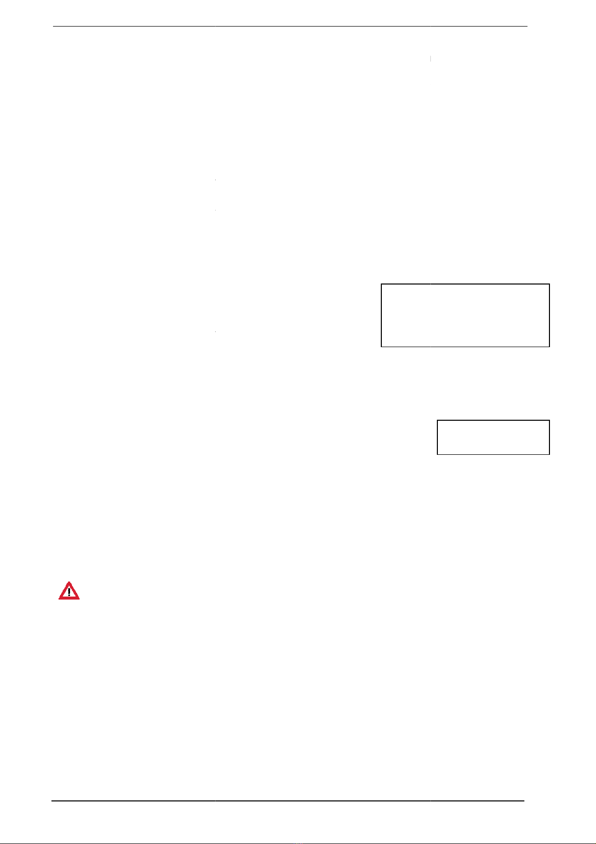
14 Remote sensor
In some cases it is applicable that the temperature is measured on another place than the controller is
suited. In that case a remote sensor can be plugged on the same 2 wires as the heaters and the
controller. The controller then works with the temperatur
possible that the contriller takes the average between its own internal sensor and the remote sensor.
14.1
ELECTRICAL CONNECTION:
The sensor should be connected according to the diagram as shown.
The sensor is connected through a 2
Cable specification: signal cable, 1x2x0,8 (shielded and twisted)
Maximum length 200m.
If these instructions are not followed the thermostat may be damaged
To conne
ct the sensor, always ensure that the heating device has been shut down. Connect the
sensor on the same wires as the clock thermostat. See Figure.
is not parallel to a 230 Volt cable.
DeltaT active
►ON
Off
between the actual temperature and the displayed temperature. This may be caused by assembly to
an outdoor wall, irradiation of the sun, monitors, etc. This temperature difference can be c
for by means of a calibration function.
Example: The difference between the measured value and the displayed value is 2
ºC too high. The correction value is therefore
-2ºC.
Destratification (delat T regulation)
Delta T active
Warm air wants to go up and stay under the ceiling of the room. The heater has the ability to push this
warm air back to the ground, and spread it into the room. This is called destratification or delta T
regulation. The thermostat measures the temperature
on ground level and reads the temperature
above in the room from the sensors on the heater. When the temperature difference between the
ceiling and ground level the ventilator inside the heaters will start to push the warm air down. (factory
When this regulation is active the heater wil also stop to burn until this temperature is
In the special installer menu the parameters of this dela T
regulations can be changed. For example the temperature
erence when the fan should start and stop can be changed. See for this in the chap
Back to factory default settings
needs to become its factory default settings back it
pressing the OK button for 10 seconds
All settings are lost and the default language menu wil
l show.
In some cases it is applicable that the temperature is measured on another place than the controller is
suited. In that case a remote sensor can be plugged on the same 2 wires as the heaters and the
controller. The controller then works with the temperatur
e from the seperate remote sensor. It is also
possible that the contriller takes the average between its own internal sensor and the remote sensor.
ELECTRICAL CONNECTION:
The sensor should be connected according to the diagram as shown.
The sensor is connected through a 2
-
wire low voltage communication system, the Argus Link.
Cable specification: signal cable, 1x2x0,8 (shielded and twisted)
If these instructions are not followed the thermostat may be damaged
ct the sensor, always ensure that the heating device has been shut down. Connect the
sensor on the same wires as the clock thermostat. See Figure.
Make sure the cable of the thermostat
is not parallel to a 230 Volt cable.
8/12
DeltaT active
RESET ALL ?
between the actual temperature and the displayed temperature. This may be caused by assembly to
an outdoor wall, irradiation of the sun, monitors, etc. This temperature difference can be c
ompensated
Example: The difference between the measured value and the displayed value is 2
ºC, i.e. the
Warm air wants to go up and stay under the ceiling of the room. The heater has the ability to push this
warm air back to the ground, and spread it into the room. This is called destratification or delta T
on ground level and reads the temperature
above in the room from the sensors on the heater. When the temperature difference between the
ceiling and ground level the ventilator inside the heaters will start to push the warm air down. (factory
When this regulation is active the heater wil also stop to burn until this temperature is
erence when the fan should start and stop can be changed. See for this in the chap
ters from the
In some cases it is applicable that the temperature is measured on another place than the controller is
suited. In that case a remote sensor can be plugged on the same 2 wires as the heaters and the
e from the seperate remote sensor. It is also
possible that the contriller takes the average between its own internal sensor and the remote sensor.
wire low voltage communication system, the Argus Link.
ct the sensor, always ensure that the heating device has been shut down. Connect the
Make sure the cable of the thermostat
Room thermostat MTC
14.2
Setting the controller for the
Menu (M) Installer
PIN[0543]
Exit the menu by pressing the M button 2 times.
14.3 Average temperatures
The controller can also calculate the average between its
internal sensor and the remote sensor. Selecte the option Average for that.
14.4
Errors with the remote sensor
In the case that te controller sees an error rega
sensor it will show an error on the display.
When there is no sensor found it will show error 3
When the senor is found but is not set up correctly it will show
error 4
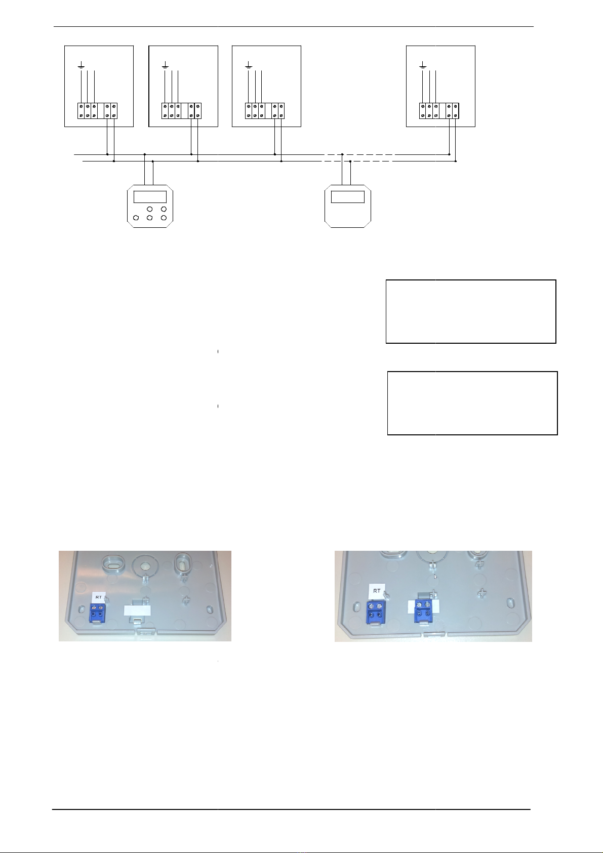
15
Optional external input
With the external input contact a heater can b
or temperature. For example
•Heating ON when the
contact
•Heating OFF when the
contact
To make the extra inputs available an extra connector needs to be put into the thermostats back.
RT is for the thermostat wires to the heaters
The right connector is for the external contact.
Attention
while connecting the extra input
The wires from this contact may not be longer then 40cm.
The wires needs to be potential free. Never
damaged.
16
Solving and analysing failures
Communication failure
: Check Heater
1 2 543
L (230V AC)
1 2 543
L (230V AC)
22°C
T herm ostat
T herm ostaat
T erm os ta to
T erm os ta t
Remote sensor
►
Thermostat
Error 4
Setting the controller for the
remote sensor
PIN[0543]
Remote sensor
Exit the menu by pressing the M button 2 times.
The controller can also calculate the average between its
internal sensor and the remote sensor. Selecte the option Average for that.
Errors with the remote sensor
In the case that te controller sees an error rega
rding the remote
sensor it will show an error on the display.
When there is no sensor found it will show error 3
When the senor is found but is not set up correctly it will show
Optional external input
With the external input contact a heater can b
e switched on or off independent from the clock program
contact
closes
contact
closes
To make the extra inputs available an extra connector needs to be put into the thermostats back.
RT is for the thermostat wires to the heaters
The right connector is for the external contact.
while connecting the extra input
The wires from this contact may not be longer then 40cm.
The wires needs to be potential free. Never
apply
any power to these wires, the thermostat will be
Solving and analysing failures
: Check Heater
Address
1 2 543
L (230V AC)
1 2
3
L (
2
3
0
V
A
C
)
22°C
Rem o te sens or
Ex ter ne sensor
So nde distanc e
Abs tands fü ler
Se nsor e re mo to
Czujn ik zew net
Dalk ovy senzor
Nuotol. ju tik lis
9/12
Remote sensor
►
used
not used
Average
Thermostat
Error 4
20,5 ºC
e switched on or off independent from the clock program
To make the extra inputs available an extra connector needs to be put into the thermostats back.
any power to these wires, the thermostat will be
54
3
L (
2
3
0
V
A
C
)
Room thermostat MTC
10/12
Heater 1 XR NG ADJ.
Error A1 (1)
IGNIT ERROR
Reset heater
Heater Error
20,5 ºC
Heater 1 N.C.
Heater 1 XR NG 10kW
STANDBY_0
Tcy Ttop 23
Tx1 22 Tx2 22
Heater 1 XR NG 10kW
STANDBY_0
Ion 0 Ac 0 SF 0
Mi3480 Ig4740 Ma6000
The thermostat can not communicate with the heaters.
Check if the dipswitches are set up right.
Error from the heater
When one or more heater(s) has an error message, it appears
on the display of the thermostat.
By pressing the Info button, you can obtain more information about the error message. With the + and
– buttons, you can select different heaters if connected.
When, for this error message, resetting the room heater is an
option, this also appears in the display. You can reset the heater
by pressing OK.
NOTE: If a room heater frequently goes on failure, do not
continue to reset; this can damage it. Let a recognised installer
examine the room heater.
17 Obtaining extra information from the connected heaters
When the info button is pressed for 5 seconds a special information menu is showed. By pressing the
+ or – button the status of all the connected heaters can be checked. By pressing the Info button
again more information about the selected heater will appear. The information will be shown in the
English language.
To exit the information menu press the M button.
When no heater is found the display will show Heater N.C. not connected
Screen 1
Shows the heater type
Screen 2
line 1: shows the discription of the connected heater
line 2: shows the status of the heater line 3 and 4: shows the temperatures from the internal sensors.
Ycy = flue temperature if the sensor is fitted (optional)
Ttop: temperature of the air where the heater is located.
Tx1 and Tx2: Temperatures from the sensor mounted on the
heatexchanger
screen 3
line 1: shows the discription of the connected heater
line 2: shows the status of the heater
line 3 and 4:
Ion = ionisation level 0 -90
Ac = actual speed or the burnerfan
Sf = actual modulation level of the system fan 0-255
Mi = minimum speed of the burnerfan
Ig = ignition speed of the burnerfan
Ma = maximum speed of the burnerfan
Screen 4
Line 1: Shows the connected heater
Line 2: status
Line 2: Nr of days that the heater is on electric power.
Line 4: Nr of burning hours.
Screen 5
Line 1: Shows the connected heater
Line 2: Nr of success ignitions.
Line 3: Nr of failed ignitions.
Line 4: Nr of flame failures.
Heater 1 HA NG 50KW
Heater 1 HA NG 50KW
BURN_0
Appl.act.days : 15
Burn.act.hours : 25
Heater 1 HA NG 50KW
Ignit.OK : 20
Ignit.failed : 2
Flame failures: 1

Room thermostat MTC
11/12
Screen 6
Shows the last 16 E errors. These errors can reset automaticly.
The blinking nr is the last error. The CRC code is the software
version in the heater.
Screen 7
Shows the last 16 A errors. These errors have to be reset by
hand. The blinking nr is the last error. The CRC code is the
software version in the heater.
18 Installer menu
Menu (M) installateurPIN 0543
The functioning of the heater and the controller can be changed by changing the parameters in the
installer menu.
The following options are available
•Heater modus (modulation from the heater)
oHeater full (fully modulatin) (Default)
oHeater high (Only on high position)
oHeater mid (Only on middle position)
oHeater low(Only on low position)
oHeater low&mid (Low and middle position)
oHeater mid&high (Middle and high position)
•deltaT hysterese
oHystt up 12°C (Value for switching the delta T ON)
oHyst down 8°C (value for swiching OFF)
•Delta T2Hystereses (Not used)
oHyst up 4°C
oHyst down 2°C
•Hystereses (computing value for thermostat)
o0,3°C
•I Factor (computing value for thermostat)
oI 5min
•Delta T2 regeling (not used)
oON / OFF
•External sensor
oON /OFF / average
•View mode Only
oON/OFF
With this option the heat demand from the thermostat is disabeled. The
thermostat can be uses as a remote status reader. To exit the view mode press
the M button 10 seconds and enter the installer menu again.
•External Input
oClosed=Burn
oClosed is OFF (standard)
19 Internal battery
When the thermostat is connected to the room heater, it does not use power from the internal battery.
This battery only serves to allow the internal clock to run on in case of a power failure. The
programmed data always remains in memory. This means that the battery, too, will stand years of
use.
When the battery is empty, the clock of the thermostat will be on 00:00 after a power failure of the
room heater that has number 1.
Heater 1 33 33 42 80
CRC:C04D 42 -- -- --
Blocking -- -- -- --
History:
--
--
--
--
Heater 1 1 1 03 09
CRC:C04D 01 -- -- --
Llocking -- -- -- --
History:
--
--
--
--
Room thermostat MTC
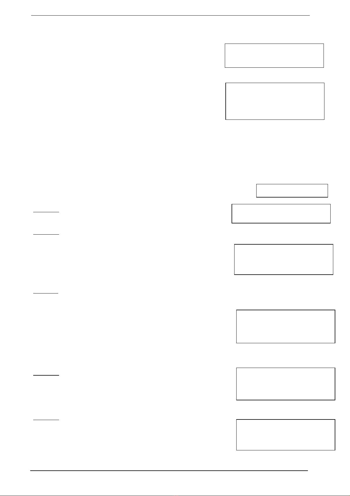
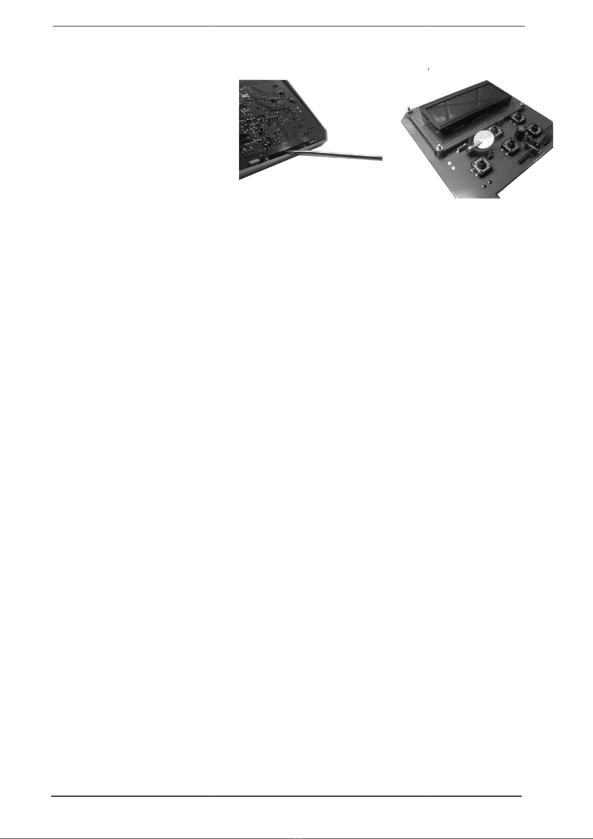
If it is necessary to replace the battery:
flat screwdriver for this and push it into the opening on the botto
Carefully prise the print plate out of the top of the thermostat using a flat screwdriver. See picture.
Carefully prise the print plate out of
the holder (see picture). Then prise
the battery out of the holder and
insert a new battery. Click the
thermostat back together again.
Note: Do not dispose the battery in
your regular household waste.
Dispose it separately in
accordance with national
guidelines.
20
Maintenance and service
Under normal use, the thermostat requires no maintena
In a very dusty environment it may be necessary to clean the ventilation openings of the temperature
sensor.
Clean the device exclusively with a dry or moist lint
Waste processing
At the end of the
life cycle, the thermostat should be disassembled by an expert and processed in an
environmentally-
friendly way in accordance with the relevant national regulations.
Do not dispose the battery in your regular household waste. Dispose it separately in accor
national guidelines.
If it is necessary to replace the battery:
Click the top of the thermostat loose from the wall plate. Use a
flat screwdriver for this and push it into the opening on the botto
m of the thermostat.
Carefully prise the print plate out of the top of the thermostat using a flat screwdriver. See picture.
Carefully prise the print plate out of
the holder (see picture). Then prise
the battery out of the holder and
Note: Do not dispose the battery in
Maintenance and service
Under normal use, the thermostat requires no maintena
nce.
In a very dusty environment it may be necessary to clean the ventilation openings of the temperature
Clean the device exclusively with a dry or moist lint
-
free cloth. Beware of moisture inside the device.
life cycle, the thermostat should be disassembled by an expert and processed in an
friendly way in accordance with the relevant national regulations.
Do not dispose the battery in your regular household waste. Dispose it separately in accor
12/12
Click the top of the thermostat loose from the wall plate. Use a
m of the thermostat.
Carefully prise the print plate out of the top of the thermostat using a flat screwdriver. See picture.
In a very dusty environment it may be necessary to clean the ventilation openings of the temperature
free cloth. Beware of moisture inside the device.
life cycle, the thermostat should be disassembled by an expert and processed in an
friendly way in accordance with the relevant national regulations.
Do not dispose the battery in your regular household waste. Dispose it separately in accor
dance with
Table of contents


