Climax Technology vesta series Operating instructions

August15,2013

Table of Contents
1.INTRODUCTION..................................................................................................................1
1.1.THE MX MEDICAL AND INTRUSION ALARM SERIES.............................................................1
1.2.WHAT’S IN THE BOX..............................................................................................................2
2.SYSTEM OVERVIEW..........................................................................................................3
2.1.IDENTIFYING THE PARTS .......................................................................................................3
2.2.POWER SUPPLY ....................................................................................................................7
3.INSTALLING MX..................................................................................................................8
4.PROGRAMMING MX...........................................................................................................9
4.1.PC PROGRAMMING...............................................................................................................9
4.1.1.Installing USB Driver...................................................................................................9
4.1.2.PC Programming Tool..............................................................................................16
4.2.WEB PROGRAMMING ..........................................................................................................47
4.2.1.Installing the Finder Software ................................................................................ 47
4.2.2.Programming MX.......................................................................................................50
4.3.SMS PROGRAMMING..........................................................................................................69
5.DEVICE MANAGEMENT...................................................................................................74
5.1.LEARNING IN PENDANT #1, PENDANT #2 AND OTHER DEVICES.......................................75
5.1.1.Learning in Pendant #1 ............................................................................................75
5.1.2.Learning in Pendant #2 ............................................................................................77
5.1.3.Learning in Other Devices.......................................................................................79
5.2.REMOVING PENDANT #1, PENDANT #2 AND OTHER DEVICES..........................................80
6.OPERATION.......................................................................................................................81
6.1.CONTROL PANEL.................................................................................................................81
6.1.1.Idle Mode......................................................................................................................81
6.1.1.1.Answering Incoming Calls...........................................................................................81
6.1.1.2.Non-Emergency Calls ...................................................................................................82
6.1.1.3.AC Power Checkup........................................................................................................ 83
6.1.1.4.Control Panel Low on Battery.....................................................................................84
6.1.1.5.Control Panel’s Battery Disconnected......................................................................84
6.1.1.6.Devices Low on Battery................................................................................................ 84
6.1.1.7.Automatic Check-In Reports....................................................................................... 85
6.1.1.8.Inactivity Timer ............................................................................................................... 85
6.1.2.Alarm Activation.........................................................................................................88

6.1.3.Arming/Disarming the System...............................................................................97
6.1.4.Voice Prompts ............................................................................................................99
6.1.5.Walk Test (Range Test)...........................................................................................100
6.1.6.Factory Reset............................................................................................................100
7.APPENDIX .......................................................................................................................101
7.1.CONTACT ID COMMUNICATIONS PROTOCOL AND FORMAT .............................................101
7.1.1. Handshake Tones .......................................................................................................101
7.1.2. Placement .....................................................................................................................101
7.1.3. Composition.................................................................................................................101
7.1.4. Message Blocks ..........................................................................................................102
7.1.5. Placement .....................................................................................................................102
7.1.6. Message Composition...............................................................................................102
7.1.7. Data Tones....................................................................................................................102
7.1.8. Kiss off (Acknowledgement) Tones .......................................................................103
7.1.9. Contact ID Event Codes............................................................................................103
7.2.SIADIGITAL COMMUNICATION STANDARD.......................................................................105
7.3.SCANCOM EVENT CODES.................................................................................................106
7.4.TUNSTALL TTNEW EVENT CODES..................................................................................107
7.5.CLIMAX CPC DIALECT EVENT CODES.............................................................................108
7.6.FRANKLIN EVENT CODES .................................................................................................110

1
1. Introduction
1.1.The MX Medical and Intrusion Alarm Series
Climax’s MX Medical and Intrusion Alarm Series marks a watershed in the
evolvement of medical alarm systems. One of the first of Climax’s wireless
medical alarms to be integrated with an intrusion alarm system, the MX Series
not only provides thorough care for your loved ones at home but also protects
your house and property when you are away. Incorporating various
cutting-edge telecare technologies, the MX Series features a new,
user-friendly three-button design that fully utilizes the flexibility and versatility
of the system. The user can summon emergency help by one press on the red
button and arm his house by one press on the yellow button. Events
happening at home will be reported to the monitoring center via the Contact ID,
Tunstall (TT New), Climax CPC Dialect or 4+2 Franklin communication
protocols. Living under protection and going in and out in peace have never
been easier.
MX Models
ModelAlarmcommunicationspath(s)CompatibilitywithEZ‐1orEZ‐2
MX‐2PSTNEZ‐1orEZ‐2
MX‐3GSM/3GEZ‐1
MX‐6EthernetandPSTNEZ‐1orEZ‐2
MX‐8EthernetandGSM/3GEZ‐1

2
1.2.What’s in the Box
Your MX sample package includes the following items:
zControl Panel
zAC adaptor for the Control Panel
zUSB cable
zCD-ROM containing
- MX Installation and Operation Guide
- USB Driver for MX
- PC Programming Tool
- The Finder software (MX-6 and MX-8 only)
3
2. System Overview
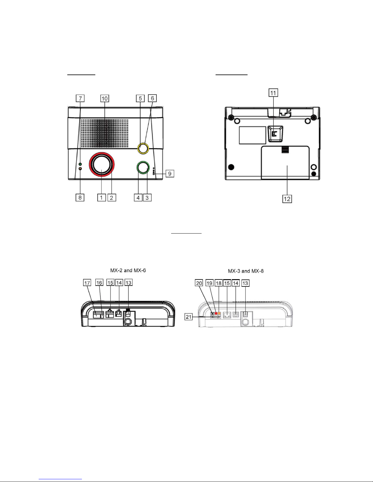
2.1.Identifying the Parts
Top View Back View
Side View

4
Control Panel Definitions
Button/LED/Component
Behavior Function/Indication
Pressed in idle/normal mode To summon emergency help
Pressed once in learning
mode To select Pendant #2
1 Red Help Button
Pressed for 3 seconds in
learning mode To delete a selected pendant
Dimly lit Idle/normal mode
Blinking 1. Guard time
2. Pauses during retries of
alarm reporting
2 Red Backlight
Brightly illuminating 1. Busy with alarm
reporting
2. After an alarm report
receives a callback and
until the call is hung up
Pressed in idle/normal mode 1. To reset the inactivity
timer
2. For the Control Panel to
report all the fault
problems it is
experiencing via voice
prompts
Pressed once before the
Control Panel dials out for
alarm reporting
To cancel the alarm reporting
Pressed once during or at
the end of a two-way
communication
To terminate the two-way
communication
Pressed for 3 seconds in
idle/normal mode To make a non-emergency
call
3 Green Reset Button
Pressed once in learning
mode To select Pendant #1
On 1. After a non-emergency
call is dialed out and until
the call ends
2. Busy with status
reporting
3. When two-way
communication is
opened after an
incoming call is picked
up and until the call ends
4 Green Backlight
Off 1. Idle mode
2. Pauses during retries of
status reporting

5
Button/LED/Component
Behavior Function/Indication
4 Green Backlight
Blinking (on MX-2 and MX-6
only) The Control Panel has a
phone line fault.
Pressed once when serving
as an inactivity, check-in/out
or away/home button
To toggle on/off the inactivity
timer
Pressed once when serving
as a security button To arm the system
Pressed once when serving
as a non-emergency button To make a non-emergency
call
Pressed for 3 seconds To enter learning mode
5 Yellow Button can
serve as:
- Inactivity Button
- Check-in/out Button
- Away/Home Button
- Non-Emergency Call
Button
- Security Button
Pressed once in learning
mode To exit learning mode
Steady on The inactivity timer is on.
Off The inactivity timer is off.
6 Orange Backlight
Blinking The Control Panel is in
learning mode.
Steady on AC power is on.
Blinking twice every second AC power fails.
7 Green LED (Volume
Switch)
Pressed once To increase the speaker
volume
Pressed once To lower the speaker volume
Blinking every 3 seconds The Control Panel is low on
battery or is having an
overvoltage condition.
Blinking twice every second A device is low on battery or
is tampered with.
8 Orange LED (Volume
Switch)
Off All the conditions signified by
this blinking orange LED
have been removed.
9 Microphone
10 Speaker
11 Battery Switch On/off
12 EZ-1/EZ-2 Lid
13 DC Jack Connects to a DC 12V 2Aswitching power adapter.
14 USB Port
15 Ethernet Port (On MX-6 and MX-8 only)
16 Phone Jack Marked
Connects to a phone line from the wall.
17 Phone Jack Marked Connects to a telephone unit.

6
Button/LED/Component
Behavior Function/Indication
On Failed registration
<
<N
NO
OT
TE
E>
>
)Registration will fail
when an AC power
failure occurs.
18 GPRS/GSM or 3G Fault
Indicator (orange)
Off Successful registration
19 GPRS/GSM or 3G
Status Indicator (red) Blinking
When the GPRS/GSM or 3G
module operates normally
20 GPRS/GSM or 3G Reset
Button Pressed for one second
To reset GPRS/GSM or 3G
21 SIM Card Base Insert your SIM card in this slot.

7
2.2.Power Supply
zPlug the AC power adapter into the Control Panel’s DC jack and connect
to the mains power. Make sure that you use an adapter with the
appropriate AC voltage rating to prevent component damage. An AC-DC
12V/2A switching power adapter is generally used to power the standard
version of the Control Panel.
zIn addition to the AC power adapter, a rechargeable battery is installed
inside the Control Panel to serve as a backup in case of a power failure.
zDuring normal operation, the AC power adapter is used to supply power to
the Control Panel and at the same time recharge the battery. It takes
approximately 72 hours to fully charge the battery.
zIf the battery switch is set as OFF, the battery will not be charged when
AC power is connected and nor will it serve as a backup power source
when AC power is missing. You need to switch the battery to ON for it to
be charged when AC power is connected and serve as a backup power
source when AC power is missing.

8
3. Installing MX
Step 1. Choose a suitable location for the Control Panel. The Control Panel
requires the mains power and PSTN (MX-2 and MX-6), GSM/3G
(MX-3 and MX-8) and/or Ethernet (MX-6 and MX-8) connections and
should be easily accessible. It should not be placed in a damp
location such as a bathroom or close to a heat source like a
microwave oven, which could reduce signal strength.
Step 2. Plug the USB cable into the Control Panel’s USB port and connect it to
a PC for MX programming.
Step 3. Connect a PSTN line and a telephone line to the Control Panel for MX
to operate via PSTN (MX-2 and MX-6 only).
Step 4. Insert a SIM card into the SIM card base on the rear side of the Control
Panel for MX to operate via GPRS and GSM or 3G (MX-3 and MX-8
only).
<
<N
NO
OT
TE
E>
>
)It is recommended that you disable the SIM card’s PIN code before you
insert the SIM card into the Control Panel.
)The SIM card will delete its messages whenever the Control Panel is
powered on.
Step 5. Plug an IP cable into the Control Panel’s Ethernet port and connect to
an Ethernet network for MX to operate via Ethernet (MX-6 and MX-8
only).
Step 6. Plug the AC power adaptor into the Control Panel’s DC jack and
connect to the mains power. The Control Panel will emit two beeps to
indicate the system is now ready for further operation.
9
4. Programming MX
4.1.PC Programming
4.1.1. Installing USB Driver
Please first install the USB Driver provided in your CD-ROM on your PC.
<
<N
NO
OT
TE
E>
>
)It is recommended that you use Windows XP or Windows 7 operating
systems.
Step 1. Plug the USB cable into the Control Panel’s USB port and connect it to
a PC.
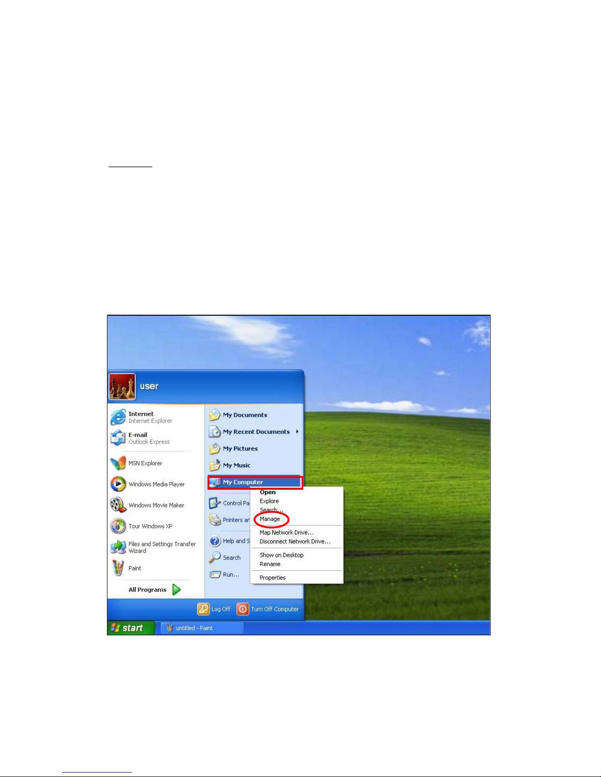
Step 2. Insert the supplied CD-ROM into your CD-ROM drive and find the
“USB Driver” folder (you may copy and paste the folder to your
desktop for later use). Click the “Start” button at the bottom left-hand
corner of the screen and then click “My Computer” and “Manage.”
10
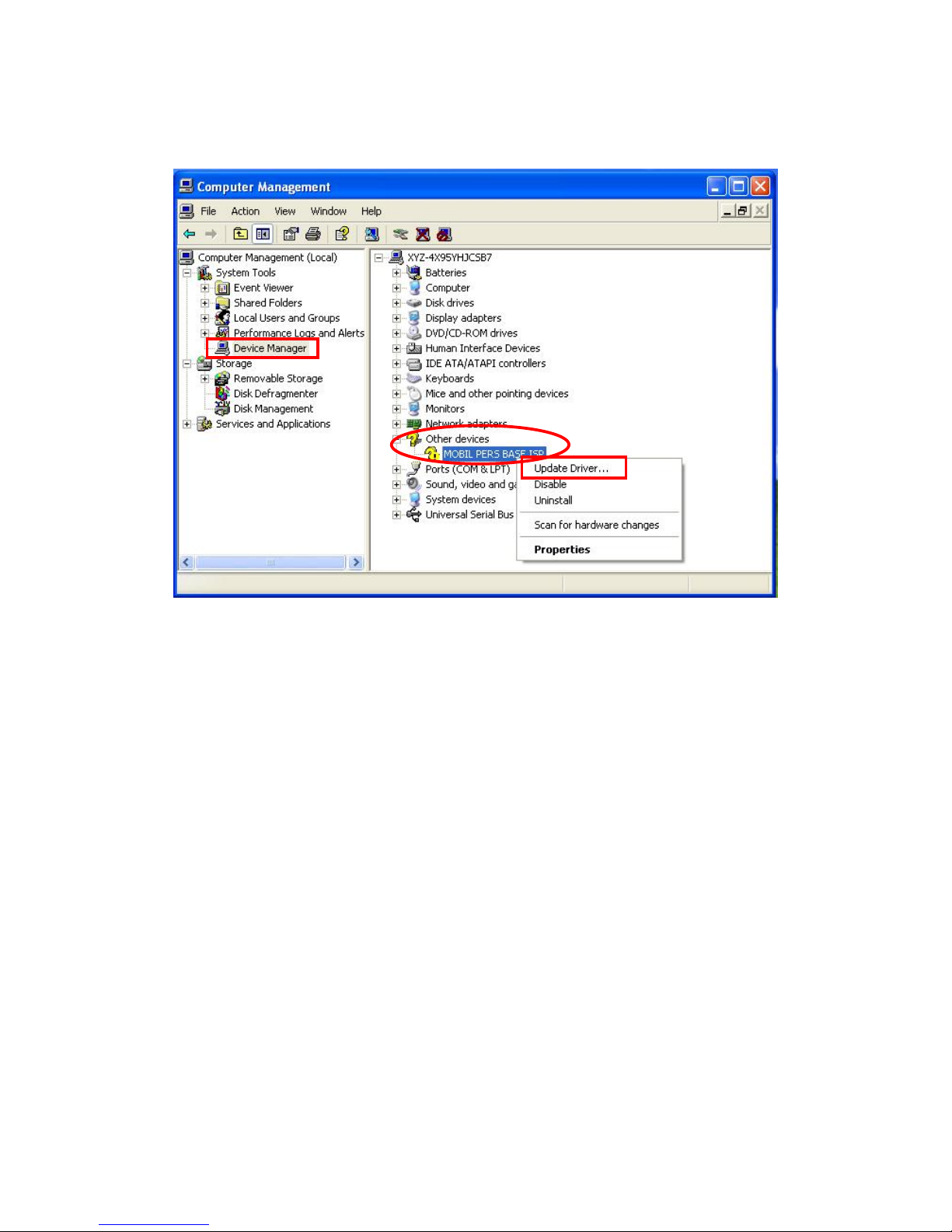
Step 3. Click on the “Device Manager” icon and find “MOBIL PERS BASE ISP”
under “Other devices.” Click “Update Driver.”
11
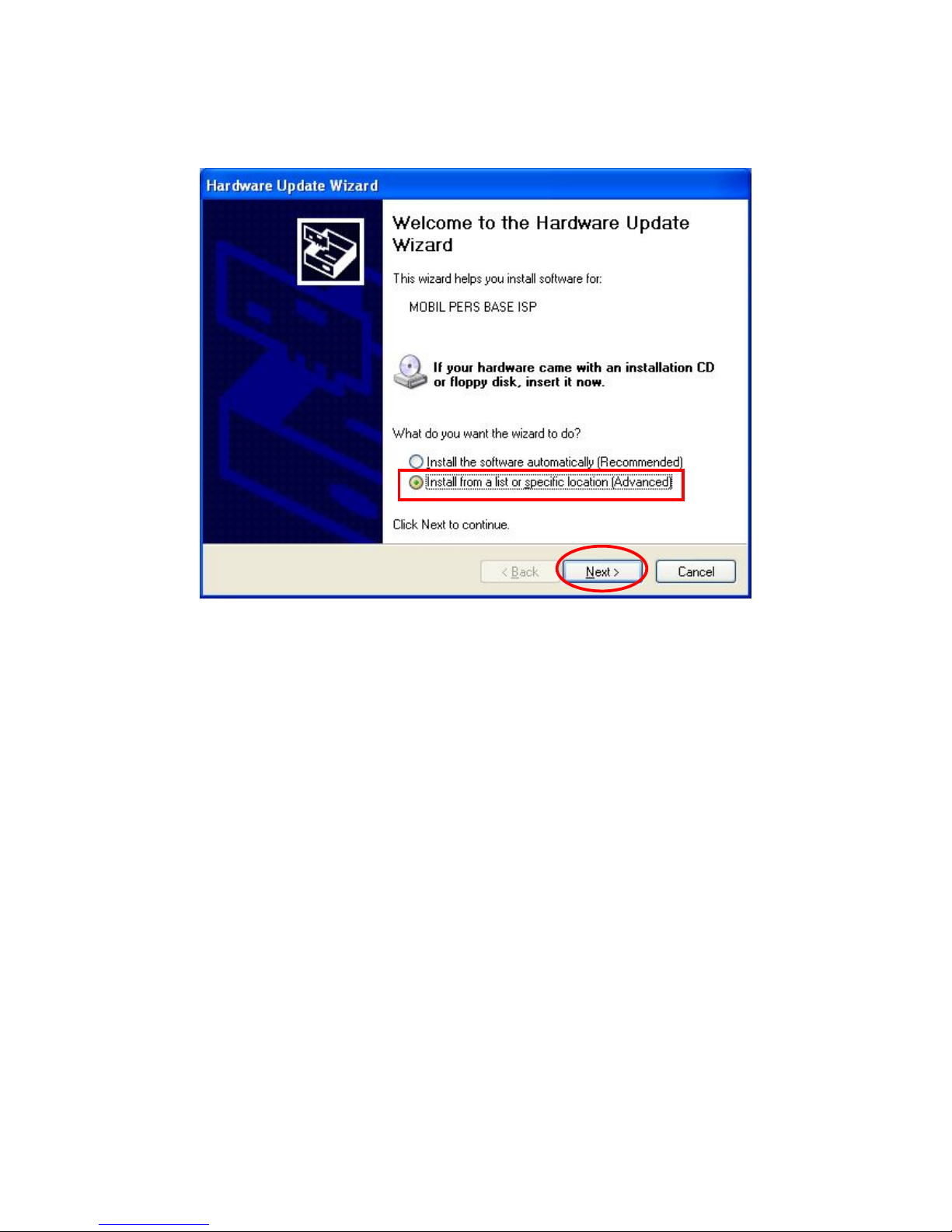
Step 4. When the Hardware Update Wizard window pops up, select “Install
from a list or specific location (Advanced)” and click “Next.”

12
Step 5. Search for the USB Driver folder. If you have copied and pasted the
USB Driver folder to your desktop, tick “Include this location in this
search” and click “Browse.”
Step 6. Select the “USB Driver” and click “OK.”
13
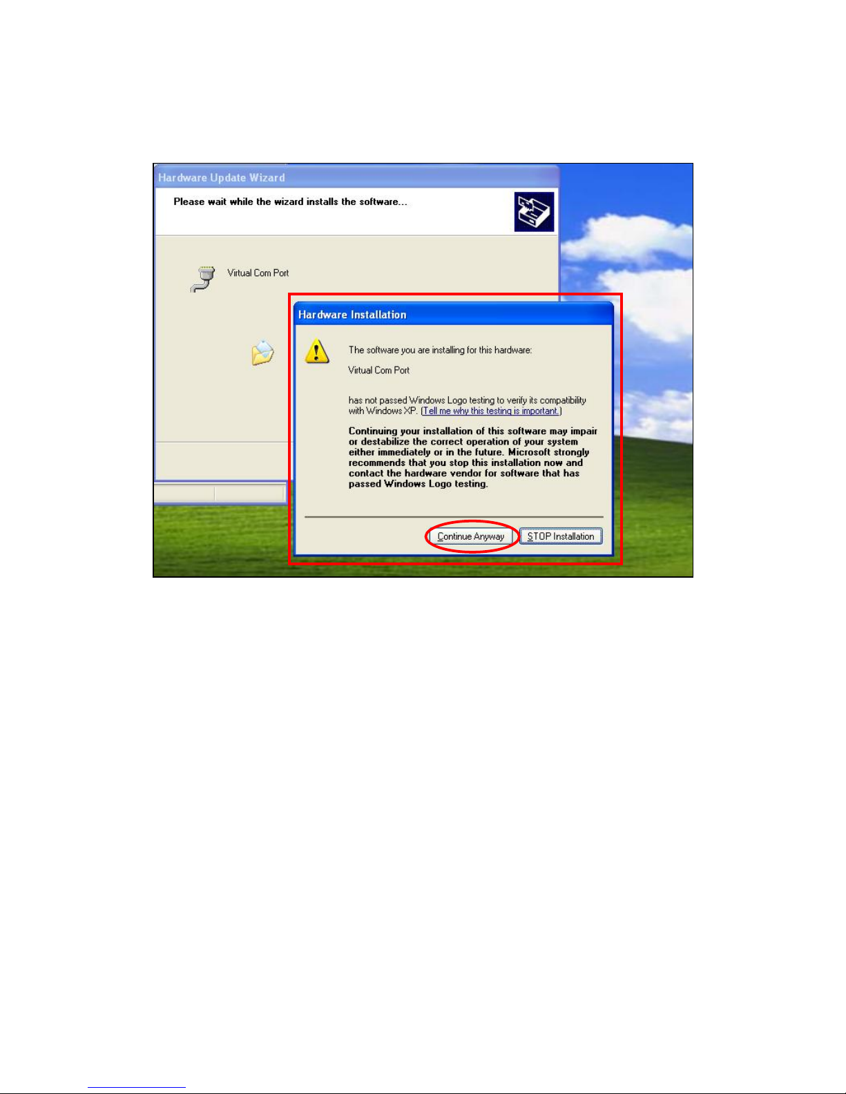
Step 7. It takes a short while for your PC to install the USB Driver. If the
Hardware Installation warning window pops up, please click
“Continue Anyway.”
14
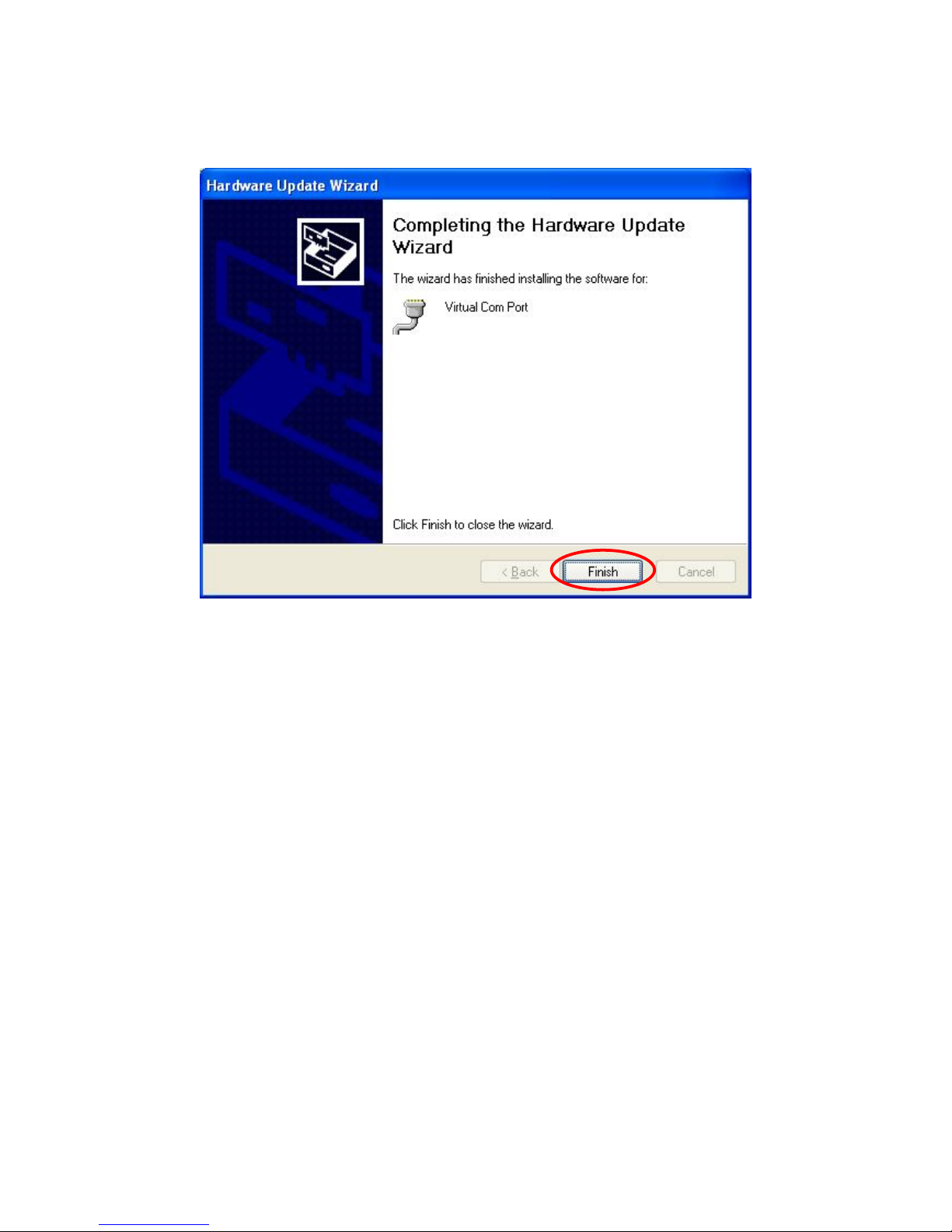
Step 8. When the installation has been completed, click “Finish” on the
Hardware Update Wizard window to close the wizard.
15
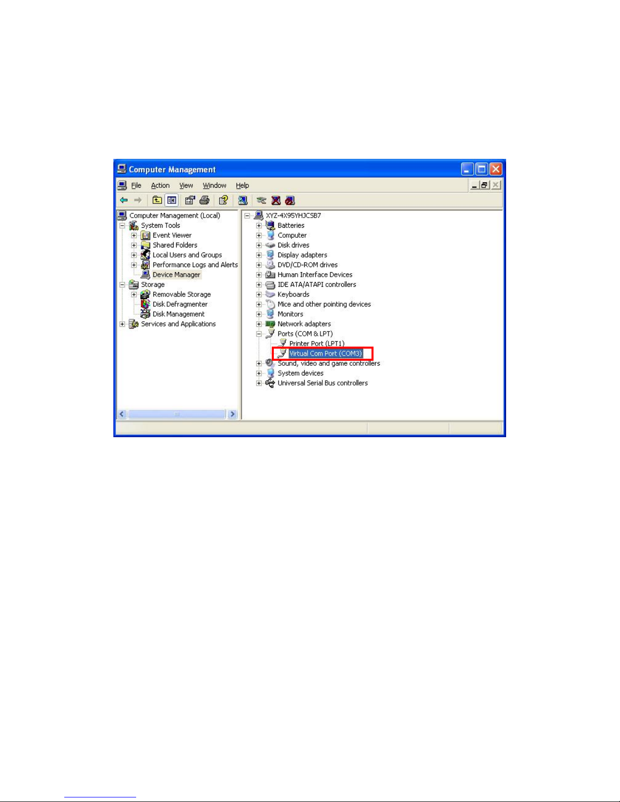
Step 9. Please remember the COM port number of MX as shown in the
“Device Manager” section. You will need the COM port number when
doing PC programming.
Now that the USB Driver has been successfully installed, you can
proceed with PC programming of MX.
16
4.1.2. PC Programming Tool
You can easily configure the Control Panel via the PC Programming Tool
provided in the CD-ROM.
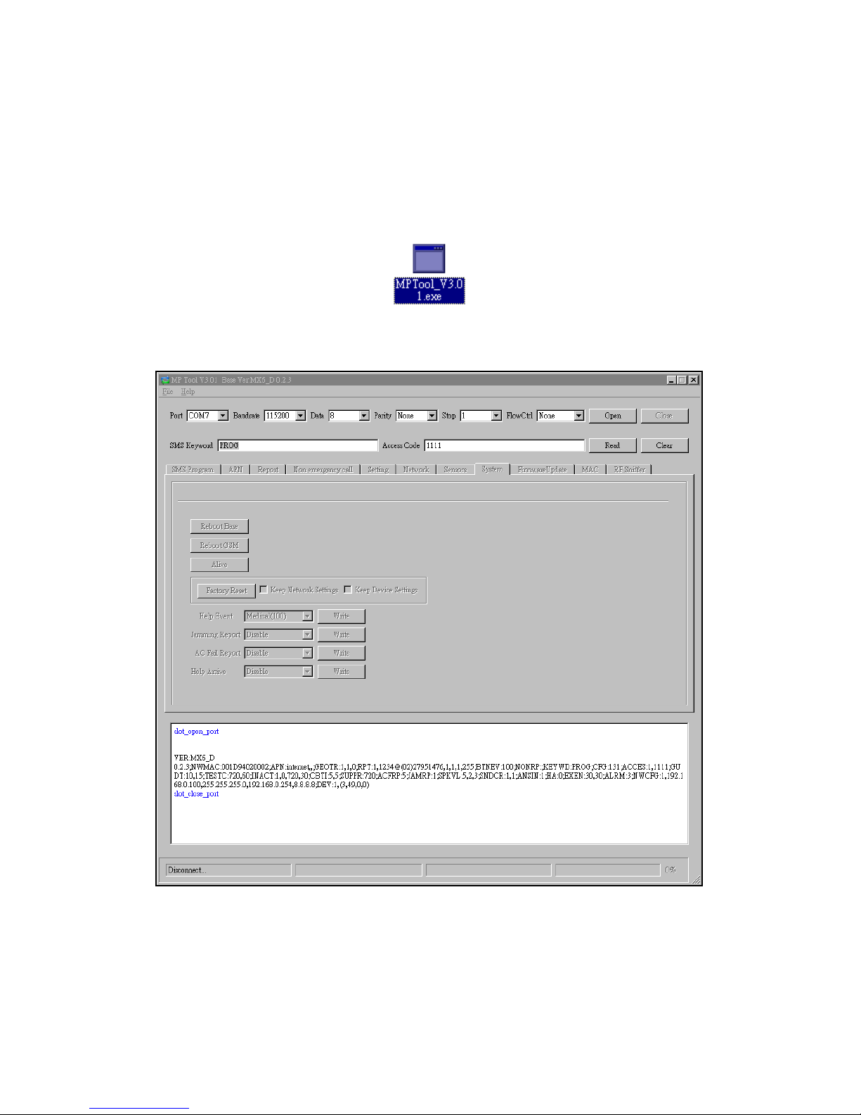
Step 1. Find and open the “PC Programming Tool” folder in the supplied
CD-ROM. Click “MPTool_x.xx.exe” to execute the programming tool.
The following configuration screen will be opened.

17
Step 2. Select the following settings in the top section of the configuration
screen and click “Open.”
zPort: Select the COM port generated for MX after installing the
USB Driver (the USB port connected to MX).
zBaud rate: 115200
zData: 8
zParity: None
zStop: 1
zFlowCtrl: None
Other manuals for vesta series
1
This manual suits for next models
5
Table of contents
Other Climax Technology Personal Care Product manuals


