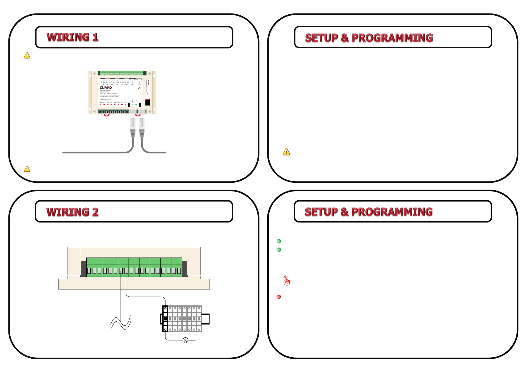
manuals.online logo
Brands
  1. Home
  2. •
  3. Brands
  4. •
  5. Climax
  6. •
  7. Relay
  8. •
  9. Climax CL-DR-RL8X8A-N User manual

Climax CL-DR-RL8X8A-N User manual

Other Climax Relay manuals

Climax CL-AB-5AMR2 User manual

Climax

Climax CL-AB-5AMR2 User manual

Climax CL-PK-MR2 User manual

Climax

Climax CL-PK-MR2 User manual

Climax CL-DR-RL16X8A User manual

Climax

Climax CL-DR-RL16X8A User manual

Climax CL-PK-CPMR2) User manual

Climax

Climax CL-PK-CPMR2) User manual

Popular Relay manuals by other brands

Shelly Pro Series user manual

Shelly

Shelly Pro Series user manual

GE MVAX 11 Technical manual

GE

GE MVAX 11 Technical manual

ABB RELION REF615R manual

ABB

ABB RELION REF615R manual

Pilz PNOZ X10 Technical instructions

Pilz

Pilz PNOZ X10 Technical instructions

Kemo Electronic B197 quick guide

Kemo Electronic

Kemo Electronic B197 quick guide

Seg MRM3 manual

Seg

Seg MRM3 manual

Basler BE1-700C manual

Basler

Basler BE1-700C manual

CD Automation REVEX 2PH 280A user manual

CD Automation

CD Automation REVEX 2PH 280A user manual

ABB SPAJ 142 C User manual and technical description

ABB

ABB SPAJ 142 C User manual and technical description

Ruelco 1S04 Operation manual

Ruelco

Ruelco 1S04 Operation manual

Basler V3E Z1P B2C1F instruction manual

Basler

Basler V3E Z1P B2C1F instruction manual

Doepke Dupline DSM 2 operating instructions

Doepke

Doepke Dupline DSM 2 operating instructions

Siemens SIRIUS 3RT1966-4D Original operating instructions

Siemens

Siemens SIRIUS 3RT1966-4D Original operating instructions

GE DGP instruction manual

GE

GE DGP instruction manual

Kyongbo Electronics GDR-D01 user manual

Kyongbo Electronics

Kyongbo Electronics GDR-D01 user manual

Siemens SIPROTEC 4 user manual

Siemens

Siemens SIPROTEC 4 user manual

Siemens BD2-AK03X/FS Series installation instructions

Siemens

Siemens BD2-AK03X/FS Series installation instructions

Leuze MSI-SR5B Original operating instructions

Leuze

Leuze MSI-SR5B Original operating instructions

manuals.online logo
manuals.online logoBrands
  • About & Mission
  • Contact us
  • Privacy Policy
  • Terms and Conditions

Copyright 2025 Manuals.Online. All Rights Reserved.

8X8A Relay Module (CL-DR-RL8X8A-N)
Rail Mounting
8X8A Relay Module is designed to be installed on a standard
35 mm wide DIN rail (EN 50022, BS 5584).
Hook the module from the top, pull down the rail mounng
clips, push the module to the rail and release the rail
mounng clips.
Screw Mounting
Screw the module to any surface through 4 corner screw
holes.
3
4
1
2
INSTALLATION GUIDE version 1.0.1
Input Voltage
18V-24V DC (24V DC is recommended)
Input Current
170mA (for 24V DC)
I/O Connecons
C-Bus
2 X RJ45
Output
8 X relay channel -8A per Channel
(rising-cage 5mm screw terminals)
Product Specificaon
1. Screw holes
2. Output connectors
3.Rail mounng clips
4. Channel LEDs
5. Status LEDs
6. Control buons (1-8)
7. RS-485 jack
CL-DR-RL8X8A-N
C-Bus
C-Bus
Power In: 24V DC, 170mA max, from data bus
1
2
3
1
1
4
1
5
7
6 3
7
#2
#3#4
#5
#8 #1
#6#7
C-Bus
C-Bus
#2
#3#4
#5
#8 #1
#6#7
Compatible with Control4
CL-DR-RL8X8A-N
C-Bus
C-Bus
Power In: 24V DC, 170mA max, from data bus
12
3
Change Module Address
In order to change the module address follow steps below consecuvely and uninterruptedly:
1. Disconnect the main power. Hold buon #1 & #2 simultaneously (buon’s and LED’s number
sequence is considered from right to le as shown in following picture) .
2. Reconnect the main power. Release buon #2 aer LEDs #1 to #4 flashed. Then release buon #1
aer LEDs #1 and #2 flashed. Power LED will start flashing quickly.
3. Press buon #1, 4 mes. Then the module address will be displayed by LEDs in binary.
4. Press buon #1 to increase the module address and buon #2 to decrease it.
5. Press buon #3 to save the module address and buon #4 to cancel. Aer saving the new module
address or canceling the process, the module will reset.
The devices which are connected from a common interface cannot have same module
address.
To: Next Module
From: Previous Module
Main N
MODE
Circut
Breaker
MODE
Circut
Breaker
MODE
Circut
Breaker
MODE
Circut
Breaker
MODE
Circut
Breaker
MODE
Circut
Breaker
MODE
Circut
Breaker
MODE
Circut
Breaker
57
68
Before wiring the device, always unplug the main power.
Follow this wiring to setup the module.
Follow the diagram below to apply appropriate output/input and protect module in case of
unwanted short circuit.
Enable/disable Autosave
If autosave funcon is acvated, reconnecng main power will set all outputs to the last status
(before power outage).
In order to enable/disable autosave follow steps below consecuvely and uninterruptedly:
1. Disconnect the main power. Hold buon #1 & #2 simultaneously (buon’s and LED’s number
sequence is considered from right to le as shown in page 4) .
2. Reconnect the main power. Release buon #2 aer LEDs #1 to #4 flashed. Then release buon
#1 aer LEDs #1 and #2 flashed. Power LED will start flashing quickly.
3. Press buon #2, 4 mes.
4. To disable/enable autosave mode, press buon #1. LED #1 will display whether autosave mode is
disabled or enabled. If it is “on” the autosave mode is enable.
5. Press buon #3 to save new seng and buon #4 to cancel.
It is recommended to disable autosave unless it is needed to be enabled.
Module’s LEDs
Power: “Power LED” will flash smoothly. When the module is connected to main power,
Status: “Status When the module is connected to C-Bus network and receives valid data packets,
LED” flashes quickly. “Status LED” is “of” when the module doesn’t receive any data.
When the module is receiving invalid data packet, “Status LED” will remain “on” for 5 seconds.
In some cases, when a new module is added to C-Bus network, all Status LEDs might remain
“on” for 5 seconds. This situaon must not be considered as an error.
Ch1 to Ch8 : Shows the status of module’s relays. Also when the module is connected to main
power, the channel LEDs will display the module address in binary for 2 seconds.
Use the terminator socket for the last module in C-Bus network.