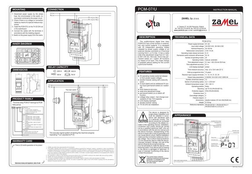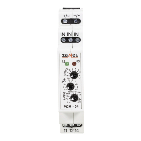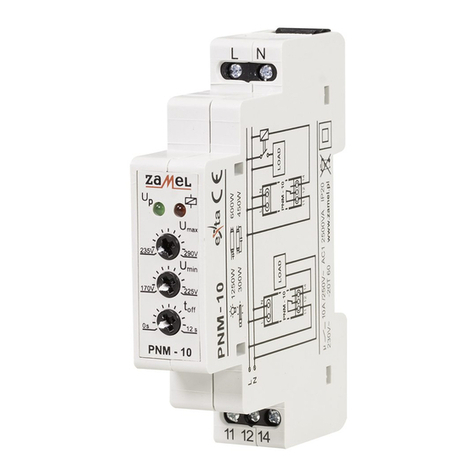
Button description:
Normal operating mode
(no time counting in progress)
Normal operating mode
(time t1 or t2 counting in progress) Programming mode
1, 2
FUN
Press and hold for 3s: opens the settings programming mode
(mode, time t1, t2, and t3). Short press twice: opens the current
settings display mode. Each next press: cycles to the next current
settings display.
Press and hold for 3s: opens the settings programming
mode (mode, time t1, t2, and t3) (interrupts the operating
mode in progress and stops the time relay).
Cycles through programmable settings (Operating
mode (FU)-t1-t2-t3- enters the selected operating
mode3) / increments the selected setting value.
OK -
Switches between a percentage display of the time left to
count down (from 99% to zero, if the time setting is > 10 s)
and the time relay operating status display (which indicates
the on / off time countdown).
Opens the displayed setting programming mode;
acknowledges the selected mode / time setting. The
modied settings are saved to the memory when
exiting the programming mode.
1
Opening the programming mode will interrupt the current operating mode and stop the time relay.
2
The last selected operating mode and the last time value settings are restored after a power cycle.
3
The operating mode is executed immediately once it has been selected, and the supply voltage does not have to be disconnected and reconnected to start it..
7-segment LED display indications:
• “–” – no time countdown in progress
• display segments cycle clockwise – the time to switch off the time relay (t1) is counted down
• display segments cycle counter-clockwise – the time to switch on the time relay (t2) is
counted down
• “FU” – operating mode
• “t1” – the time to switch off the time relay
• “t2 – the time to switch on the time relay
• “t3” – total operating mode time (applies to modes 3, 4, 25, and 26)
LED PK/t indications:
Normal operating mode:
• LED off – the time relay is OFF (outputs 11 and 12 are made)
• LED on and red – the time relay is ON (outputs 11 and 14 are made)
Setting programming mode:
• LED off – setting a value in tens of a second
• LED on and red – setting a value in seconds
• LED on and green – setting a value in minutes
• LED on and amber – setting a value in hours
DELAYED SWITCH ON – once the supply voltage has been
applied to the inputs, t1 countdown begins. When the time is
counted down to zero, the time relay is ON (make outputs 11-
14). The current mode starts again when the power supply voltage is cycled.
DELAYED SWITCH ON – once the supply voltage has been
applied to the inputs, t1 countdown begins. When the time
is counted down to zero, the time relay is ON (make outputs
11-14) for the duration of t2. The cycle is repeated when the
supply voltage is cycled.
DELAYED SWITCH OFF – once the supply voltage has been
applied to the inputs, the relay switches on immediately (make
outputs 11-14), and t2 countdown begins. When the time
counts down to zero, the time relay switches off (make outputs 11-12). The current mode starts
again when the power supply voltage is cycled.
DELAYED SWITCH OFF – once the supply voltage has been
applied to the inputs, the relay switches on immediately (make
outputs 11-14), and t2 countdown begins. When the time is
counted down to zero, the time relay is OFF (make outputs 11-
12) for the duration of t1, after which the time relay is switched ON again. The cycle is repeated
when the supply voltage is cycled.
SPECIFIC PULSE COUNT GENERATION (from the switch off
operation) – once the supply voltage has been applied to the
inputs, t1 countdown begins. When the time is counted down
to zero, the time relay is ON (make outputs 11-14) for the dura-
tion of t2, after which the time relay is OFF. This cycle repeats for the duration of t3, and when t3
expires, the time relay
SPECIFIC PULSE COUNT GENERATION (from OFF) – when a
rising edge trigger is input, the power load starts t1 countdown.
After this, the time relay is switched ON (make outputs 11-14) for
the duration of t2, after which the time relay is switched OFF. The
cycle is repeated for the duration of t3, and once it expires, the time relay is switched OFF. During the t3
countdown, all trigger inputs are ignored.
CYCLIC SWITCHING (from OFF) – once the supply voltage
has been applied to the inputs, t1 countdown begins. Once the
countdown ends, the time relay is switched ON (make outputs
11-14) for the duration of t2 after which the time relay is switched OFF (make outputs 11-12) for the
duration of t1. The system repeats this cycle until the supply voltage is isolated.
SPECIFIC PULSE COUNT GENERATION (from the switch
on operation) – once the supply voltage has been applied to
the inputs, the relay switches on immediately (make outputs
11-14), and t2 countdown begins. Afterwards the time relay is
switched OFF (make outputs 11-12) for the duration of t1, after which the time relay is ON again.
This cycle repeats for the duration of t3, and when t3 expires, the time relay is switched off.
SPECIFIC PULSE COUNT GENERATION (from ON) – when
a rising edge trigger is input, the power load switches the time
relay ON (make outputs 11-14) and t2 countdown begins. After
this, the time relay is switched OFF (make outputs 11-12) for
the duration of t1, after which the time relay is switched ON. The cycle is repeated for the duration
of t3, and once it expires, the time relay is switched OFF. During the t3 countdown, all trigger inputs
are ignored.
CYCLIC SWITCHING (from ON) – once the supply voltage has
been applied to the inputs, the time relay is immediately switched
ON (make outputs 11-14) for the duration of t2. Once the time has
been counted down, the time relay is switched OFF (make outputs 11-12) for the set t1 duration, after
which it is switched ON for t2. This cycle is repeated until the supply voltage is isolated.
DELAYED 0.5s PULSE GENERATION – once the supply volt-
age has been applied to the inputs, the set t1 is counted down.
Afterwards the time relay is switched ON (make outputs 11-14)
for 0.5s and switched OFF again (make outputs 11-12). The next time this mode is executed is when
the supply voltage is cycled again.
CONTINUOUS SWITCH ON MODE – once the supply volt-
age has been applied, the time relay remains switched ON.
The settings of t1, t2 and t3 are ignored when enabling this
operating mode.
CONTINUOUS SWITCH OFF MODE – once the supply volt-
age has been applied, the time relay remains switched OFF.
The settings of t1, t2 and t3 are ignored when enabling this
operating mode.
RISING EDGE TRIGGERED TIME PULSE – when a rising
edge trigger is input, the power load switches ON the time re-
lay (make outputs 11-14) and the set time is counted down.
Once t2 has been counted down, the time relay is OFF (make outputs 11-12). Impulse time duration
is not important here.
DELAYED SWITCH ON/OFF (retriggerable) – when a rising
edge trigger is input, the power load keeps the time relay OFF
(make outputs 11-12) and the set t1 countdown begins. When
the time is counted down to zero, the time relay is switched ON (make outputs 11-14). When a
falling edge trigger is input, t2 is counted down, after which the time relay is OFF (make outputs
11-12). If the trigger duration is < t1 setting, the time relay is not switched ON. When a trigger is
input during t2 countdown will not switch off the time relay, but t2 countdown will be reset when the
trigger edge falls down.
FALLING EDGE TRIGGERED TIME PULSE – when a falling
edge trigger is input, the power load switches ON the time
relay (make outputs 11-14) and the set time is counted down.
Once t2 has been counted down, the time relay is OFF (make outputs 11-12). If the trigger edge
falls again during the set time countdown will not restart the countdown (the system is non-
retriggerable).
DELAYED SWITCH ON/OFF (non-retriggerable) – when a ris-
ing edge trigger is input, the power load keeps the time relay
OFF (make outputs 11-12) and the set t1 countdown begins.
When the time is counted down to zero, the time relay is switched ON (make outputs 11-14). When
a falling edge trigger is input, t2 is counted down, after which the time relay is OFF (make outputs
11-12). The trigger input state can be switched during t2 countdown without affecting the operation.
If the trigger duration is < t1 setting, the time relay is not switched ON.
DELAYED SWITCH ON/OFF – when a rising edge trigger is
input, the power load keeps the time relay OFF (make outputs
11-12) and t1 countdown begins. When the time is counted
down to zero, the time relay is switched ON (make outputs 11-14). When the trigger edge falls,
the set t2 is counted down after which the time relay is switched OFF (make outputs 11-12). If the
trigger duration < set t1, the time relay is switched on for t2 only.
ALTERNATING DURATION PULSE GENERATION – when a
rising edge trigger is input, the power load switches the time
relay ON for the duration of t1, after which the time relay is
switched OFF. The next input trigger will switch the time relay ON for the duration of t2. The next
input trigger will switch the time relay ON for the duration of t1, etc. The trigger duration does not
affect the time during which the time relay remains switched ON.
BISTABLE TIME-LIMITED RELAY – when a rising edge is in-
put, the power load switches the time relay ON (make outputs
11-14) and t2 countdown begins. When the next trigger has a
rising edge or t2 expires (whichever comes rst), the time relay
is switched OFF. The trigger duration is irrelevant for the system’s operation.
FALLING EDGE TRIGGERED DELAYED SWITCH OFF –
when a trigger is input, the power load switches the time relay
ON (make outputs 11-14). When the trigger edge falls, the set
t2 is counted down to zero, after which the time relay is switched OFF (make outputs 11-12) for the
duration of t1. Before t1 expires, all trigger inputs are ignored. Once t1 has been counted down, the
time relay is switched ON again if a rising edge trigger is input.
TIME PULSE TRIGGERED WITH A RISING EDGE AND DE-
LAYED SWITCH OFF (non-retriggerable) – when a rising edge
trigger is input, the power load switches the time relay ON
(make outputs 11-14). When a falling edge trigger is detected,
the set t2 is counted down, after which the time relay is switched OFF (make outputs 11-12).
RISING/FALLING EDGE TRIGGERED PULSE – when a rising
edge trigger is input, the power load switches the time relay
ON (make outputs 11-14) for the duration of t1, after which the
time relay is switched OFF. A falling edge trigger input switches the time relay ON (make outputs
11-14) for the duration of t2, after which the time relay is switched OFF. When the time relay is ON,
the trigger inputs are ignored.
TRIGGERED DELAYED SWITCH ON – when a rising edge trig-
ger is input, the power load keeps the time relay OFF (make out-
puts 11-12); simultaneously, the set t1 countdown begins. When
the time is counted down to zero, the time relay is switched
ON (make outputs 11-14). The time relay remains ON until the
power load supply voltage is isolated, and no next trigger affects the time relay status.
TIME PULSE TRIGGERED WITH A RISING EDGE AND DE-
LAYED SWITCH OFF (retriggerable) – when a rising edge trig-
ger is input, the power load switches the time relay ON (make
outputs 11-14). When a falling edge trigger is detected, the set t2
is counted down, after which the time relay is switched OFF (make outputs 11-12). If a trigger is input
during the t2 countdown, the cycle is restarted (the system is retriggerable).
TIME PULSE TRIGGERED WITH A SPECIFIC TRIGGER DU-
RATION – when a trigger is input with a duration of t1 or longer,
the power load switches the time relay ON (make outputs 11-
14) for t2. If the trigger is < t1, the time relay is not switched ON.
When the time relay remains ON, all triggers are ignored.
S
t1 t1t2 t2
11-14
S
U
t1
11-14
S
t2 t2
11-14
S
t tt2 t2
t2
11-14
S
tt2
t2
11-14
S
tt2t1 t2 t1
11-14
S
t2 t2
11-14
S
t2 t2
11-14
U
0.5s
t1
0.5s
t1
11-14
U
t2 t2
11-14
U
t1t1
11-14
S
t1 t1 t2
11-14
S
tt2 t1 t t2
11-14
S
t1 t2 t1
11-14
S
t1 t1 t1t2 t2 t2
11-14
S
t1 t1 t2
11-14
U
11-14
U
11-14
U
t2 t1t2 t1t1 t2
11-14
U
t2 t1 t2 t1 t2t1
11-14
U
t2 t1 t1
t2
11-14
U
t2 t1t1 t2
11-14
U
t2t1 t1
t3
t2 t1 t2
11-14
S
t2t1 t1
t3
t2 t1 t2
11-14
U
t2 t1t2 t1 t2t1
11-14
t3
S
t2 t1t2 t1 t2t1
11-14
t3
