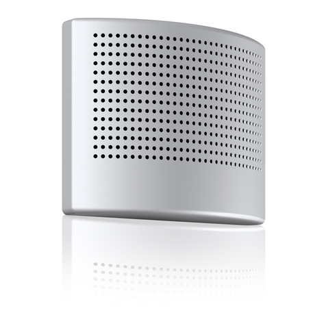
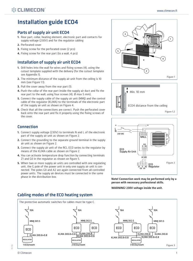
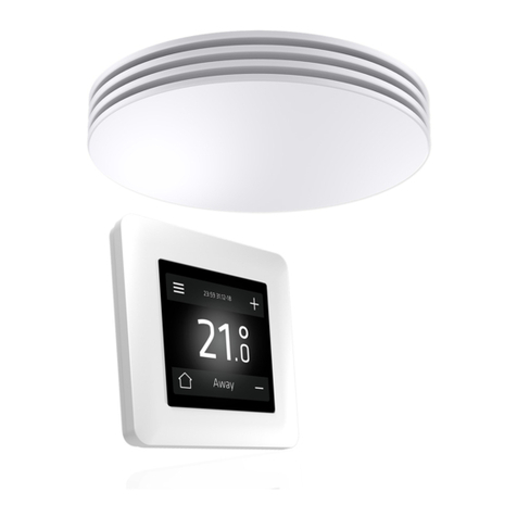
Climecon ECO-W User manual

climecon.fi
© Climecon 1
Installation manual ECO-W
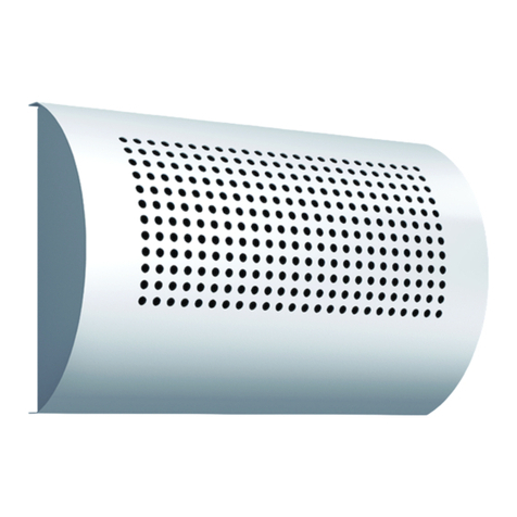
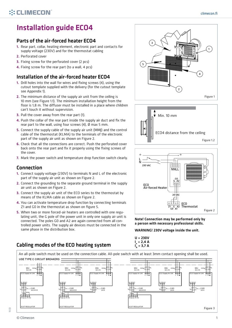
1. Components of the ECO-W
air heater
1. Body, duct connection, heating element,
electronics section and connections for supply
voltage (230 V) and controller cabling.
2. Grille
3. Grille fastening screw (2 pcs)
4. Bottom fastening screw (for the wall, 2 pcs)
Figure 2.1
2. Installation of the ECO-W air heater
1. Drill the necessary holes in the wall for cables and fastening screws by using
the template provided with the unit (see stencil in Appendix 1).
2. The minimum distance of the terminal device from the ceiling is 100 mm (see Figure 2.1).
Install the terminal device at a minimum height of 1.8 m.
Ensure that children cannot get their hands on the device.
3.
4. Insert the bottom section duct connector into the inlet air duct, and attach the body to the wall with screws (4)
(2 pcs, max Ø 5 mm).
5. Connect the supply cable (MMJ) through a double-pole switch, and the control unit’s data cable
to the connectors in the electronics section of the terminal device, as shown in Figure 2.2.
6. Ensure that the connections are correct. Place the grille back onto the body and
ensure that it is properly attached with the fastening screws.
7. Mark the power switch clearly.
Figure 2.2
Figure 1.1
230VAC
CONTROL
Modbus
TERMINATION
OFF-ON
DIP1-8:
Modbus-ID
L
N
N
L
X3
X2
X1
OFF/ON
D- D+ V
T
B A
CONTROL BUS
T
09.20
ECO-W distance from wall
Min. 10 mm
3
2
41

climecon.fi
© Climecon 2
Installation manual ECO-W
3. Connection
1.
N and L in the electronics section of the terminal device, as shown in Figures 3.2 and 3.3.
2. Connect the ground to the terminal device’s separate ground connector, as shown in Figures 3.2 and 3.3.
3. Connect the ECO series terminal device to the controller with the data cable, as shown in Figures 3.2 and 3.3.
4. Activate the terminator by moving the termination jumper to the ON position
5. DIP switch operation:
• One thermostat controls one terminal device: there is no need to change the position of the DIP switches.
move the DIP switch No 8 to the ON position.
NOTE! Electrical connections may only be made by a professional electrician.
WARNING! The supply air device carries a voltage of 230V.
U = 230V In = 1.7A
The connect signal D-/D+ is RTU.
For the BMS connection settings, see Appendix 1. ECO ModBus map.
The recommended data cable between the controller and the air heater is e.g., NOMAK 2x2x0.5+0.5
230VAC
CONTROL
Modbus
TERMINATION
OFF-ON
DIP1-8:
Modbus-ID
L
N
N
L
X3
X2
X1
230VAC
CONTROL
Modbus
TERMINATION
OFF-ON
OFF/ON
DIP1-8:
Modbus-ID
L
N
N
L
X3
X2
X1
D- D+ V
T
B A
CONTROL BUS
T
OFF ON
Bus
termination
by jumper
OFF ON
Bus
termination
by jumper
CONTROL Modbus-ID
ID: 1-4
1 =
2 =
3 =
4 =
Figure 3.1

climecon.fi
© Climecon 3
Installation manual ECO-W
The basic ECO connection, in which one ECO air heater
is controlled with a single ECO-T room control unit.
230VAC
CONTROL
Modbus
TERMINATION
OFF-ON
DIP1-8:
Modbus-ID
L
N
N
L
X3
X2
X1
OFF/ON
D- D+ V
T
B A
CONTROL BUS
T
ECO-T
D- D+ V
T
D- D+ V
T
N L
Control BUS
B A
230 VAC
Room
T
ECO air heater
One ECO-T
control unit can
control 1–4ECO
air heaters
are controlled with a single ECO-T room control unit.
230VAC
CONTROL
Modbus
TERMINATION
OFF-ON
DIP1-8:
Modbus-ID
L
N
N
L
X3
X2
X1
230VAC
CONTROL
Modbus
TERMINATION
OFF-ON
OFF/ON
DIP1-8:
Modbus-ID
L
N
N
L
X3
X2
X1
D- D+ V
T
B A
CONTROL BUS
T
OFF ON
Bus
termination
by jumper
OFF ON
Bus
termination
by jumper
CONTROL Modbus-ID
ID: 1-4
1 =
2 =
3 =
4 =
ECO-T
D- D+ V
T
D- D+ V
T
N L
Control BUS
B A
230 VAC
Room
T
ECO air heater
D- D+ V
T
N L
ECO air heater
One ECO-T
control unit can
control 1–4ECO
air heaters
a separate ECO-T control unit.
Move the DIP switch No 8 to the ON position.
The heating resistor’s maximum surface
230VAC
CONTROL
Modbus
TERMINATION
OFF-ON
DIP1-8:
Modbus-ID
L
N
N
L
X3
X2
X1
230 VAC
huone-
säädin
N
L-in L-out
Figure 3.2
Figure 3.3
Figure 3.4

climecon.fi
© Climecon 4
Installation manual ECO-W
4. Connecting the heating of several rooms to the bus
1.
The ECO connection in which the heating of several rooms has been
linked through the bus. In the example, Room No 1 has two
heaters and Room No 2 has one heater.
D- D+ V
T
N L
Control BUS
230 VAC
Room 1
Master Slave
ECO-T
D- D+ V
T
B A
T
ECO air heater
D- D+ V
T
N L
ECO air heater
One ECO-T
control unit
can control
1–4ECO air
heaters
One ECO-T
control unit
can control
1–4ECO air
heaters
ECO-T
D- D+ V
T
D- D+ V
T
N L
Control BUS
B A
230 VAC
Room 2
T
ECO air heater
The ECO connection in which the heating of several rooms has been linked
through the bus.
ON
D- D+ V
T
B A
CONTROL BUS
BUS
Term.
T
OFF
D- D+ V
T
B A
CONTROL BUS
BUS
Term.
T
ECO air heater
ECO air heater
ECO air heater
BUS:
Modbus-ID: 1..9
BUS:
Master
ON
D- D+ V
T
B A
CONTROL BUS
BUS
Term.
T
Modbus settings
Modbus ID
Stop bits
Baudrate
Master
38400
1
Modbus settings
Modbus ID
Stop bits
Baudrate
1
38400
1
Modbus settings
Modbus ID
Stop bits
Baudrate
2
38400
1
NOTE! Electrical connections may only be made by a professional electrician.
WARNING! The supply air device carries a voltage of 230V.
U = 230V In = 1.7A
The connect signal D-/D+ is RTU.
For the BMS connection settings, see Appendix 1. ECO ModBus map.
The recommended data cable between the controller and the air heater is e.g., NOMAK 2x2x0.5+0.5
Figure 4.1
Figure 4.2

climecon.fi
© Climecon 5
The ECO connection in which the heating of several rooms has been linked through the bus and the data transfer between the
rooms is done via a BMS (Building Management System) device.
D- D+ V
T
N L
Control BUS
230 VAC
Room 1
SlaveECO-T
D- D+ V
T
B A
T
ECO air heater
D- D+ V
T
N L
ECO air heater
One ECO-T
control unit can
control 1–4ECO
air heaters
One ECO-T
control unit can
control 1–4ECO
air heaters
ECO-T
D- D+ V
T
D- D+ V
T
N L
Control BUS
B A
230 VAC
Room 2
T
ECO air heater
BMS
Slave
Master
Figure 4.3

climecon.fi
© Climecon 6
Installation manual ECO-T, controller
21.0
1
2
4
3
230VAC
CONTROL
Modbus
TERMINATION
OFF-ON
DIP1-8:
Modbus-ID
L
N
N
L
X3
X2
X1
OFF/ON
D- D+ V
T
B A
CONTROL BUS
T
Figure 1.1
Figure 2.1
Figure 3.1
3. Start-up guide
1. Connect the supply voltage to the system,
which will activate the touch screen’s main view
(Figure 3.1).
2.
3. Set the language, date and time.
4. You can change the language by navigating to the
Language section in the Display settings menu.
.
5. The date and time can be set in
the Date & Time section.
6. To return to the main view, press again
7. The temperature can be adjusted in the main
view with the plus and minus symbols.
8. More detailed instructions on the system
functions are provided in a separate manual.
2. Controller installation:
1. Run the ECO-T controller unit’s data cable
from the ECO air heater to the junction box,
as shown in Figure 2.1.
2. Detach the touch screen (4) from the locking
piece (3).
3. Detach the locking piece from the bottom (1),
for example with a small screwdriver.
4. Fasten the bottom (1) to the junction box.
5. Install the cover plate (2).
6. Install the locking piece (3).
7. Connect the wires to the touch screen
connectors, as shown in Figure 2.1.
8. Push the touch screen (4) into the locking piece
(3) until you hear a click.
1. Components of the ECO-T controller
1. Bottom
2. Cover plate
3. Locking piece
4. Touch screen
More comprehensive instructions
for adjusting and scheduling room
temperature can be found via the
QR code or at climecon.fi/eco

climecon.fi
© Climecon 7
Installation manual ECO-W
NOTE! Electrical connections may only be made by a professional electrician.
Always disconnect the device from the supply voltage before maintenance!
OFF
1
3
5
2
4
2x
2x
2x
2x
230 VAC
Data

climecon.fi
© Climecon 8
Maintenance manual ECO-W
NOTE! Maintenance may only be performed by a professional ventilation installer.
Warning! The device carries a voltage of 230V!
Disconnect from the supply voltage before maintenance.
OFF
1
3
5
2
4
6
2x
3x
4x
1
0

climecon.fi
© Climecon 9
1.ECO ModBus map ; Appendix 1. ECO ModBus map
Holding
registers (4x) Unit/Value Description
1Status
2Application state 0=normal (home), 1=away
3Not used
4 Temperature setpoint
211 Date.year Not able to set via modbus
212 Date.month Not able to set via modbus
213 Date.day Not able to set via modbus
214 Clock.hours Not able to set via modbus
215 Clock.minutes Not able to set via modbus
216 Clock.seconds Not able to set via modbus
2000 Week timer master
2001 Week program1
2002 Not used Must be 1
2003 Week program 1
- Comfort start time
NOTE ! Must be dividable by 15
2004 Week program 1
- Comfort end time
NOTE ! Must be dividable by 15
2005 Week program 1
- Comfort temperature
NOTE ! Must be dividable by 5 (0,5°C)
2006 Week program 1 -
Economy temperature
NOTE ! Must be dividable by 5 (0,5°C)
2008 Not used Must be 1
2009 Week program 2 - Com-
fort start time
NOTE ! Must be dividable by 15
2010 Week program 2 - Com-
fort end time
NOTE ! Must be dividable by 15
2011 Week program 2 - Com-
fort temperature
NOTE ! Must be dividable by 5 (0,5°C)
2012 Week program 2 -
Economy temperature
NOTE ! Must be dividable by 5 (0,5°C)
2013

climecon.fi
© Climecon 10
ECO series ModBus register map
Holding
registers (4x) Unit/Value Description
2014 Not used Must be 1
2015 Week program 3
- Comfort start time
NOTE ! Must be dividable by 15
2016 Week program 3
- Comfort end time
NOTE ! Must be dividable by 15
Week program 3
- Comfort temperature
NOTE ! Must be dividable by 5 (0,5°C)
2018 Week program 3
- Economy temperature
NOTE ! Must be dividable by 5 (0,5°C)
2019 Week program 4
2020 Not used Must be 1
2021 Week program 4
- Comfort start time
NOTE ! Must be dividable by 15
2022 Week program 4
- Comfort end time
NOTE ! Must be dividable by 15
2023 Week program 4
- Comfort temperature
NOTE ! Must be dividable by 5 (0,5°C)
2024 Week program 4
- Economy temperature
NOTE ! Must be dividable by 5 (0,5°C)
2025
2026 Not used Must be 1
Week program 5
- Comfort start time
NOTE ! Must be dividable by 15
2028 Week program 5
- Comfort end time
NOTE ! Must be dividable by 15
2029 Week program 5
- Comfort temperature
NOTE ! Must be dividable by 5 (0,5°C)
2030 Week program 5
- Economy temperature
NOTE ! Must be dividable by 5 (0,5°C)
35001 Parameter system
version Read only
35002 Not used (NULL) Read only
35003 Not used (NULL) Read only
35004 Read only
35005 Parameter request
revision Read only

climecon.fi
© Climecon 11
ECO series ModBus register map
Parameter file
settings (4x) Unit/Value Description
35201 Temperature setpoint
min limit
NOTE ! Must be dividable by 5 (0,5°C)
35202 Temperature setpoint
max limit
NOTE ! Must be dividable by 5 (0,5°C)
35203 Temperature setpoint
normal NOTE! Use 4x4 instead
35204 Temperature setpoint
away
NOTE ! Must be dividable by 5 (0,5°C)
35205 Not used
35206 Week timer master
This is same as 4x2000. Does not matter which one you use
35225 Thermostat adaptivity
35226 Temp calibration
59001 Active week program
setpoint Read only
Input
registers (3x) Unit/Value Description
5HW revision
6SW version major
SW version minor
8Room temperature
9Not used
10 Not used
11 Application state
12 Application status
13 Not used
14 Temperature setpoint
15 Last user activity
(Touch display) sec
16 Not used
Start unit
18 Heating load %

climecon.fi
© Climecon 12
ECO series ModBus register map
Input
registers (3x) Unit/Value Description
101 Number of triac devices
102 alive count
103 alive count
104 alive count
105 alive count
106 alive count
alive count
108 alive count
109 alive count
110 alive count
111 Number of UI
slave devices
112 alive count
113 alive count
114 alive count
115 alive count
116 alive count
alive count
118 alive count
119 alive count
120 alive count
50020 UI serial number
low byte
50021 UI serial number
high byte
Table of contents
Other Climecon Heater manuals
Popular Heater manuals by other brands
Honeywell
Honeywell HZ-3750GP - Electronic Ceramic Tower Heater Important safety instructions
Claudgen
Claudgen SCREENZONE RAC1306 manual
Olimpia splendid
Olimpia splendid CALDOSTILE D Instructions for installation, use and maintenance
AERMEC
AERMEC Omnia UL 11 N Use and installation manual
Life zone
Life zone SGH-W6-WIQ user manual
Lowry
Lowry GSOFR2003 user manual
Klarstein
Klarstein Sanford Smart manual

Eurotops
Eurotops 26583 user manual
Master
Master MH-60V-GFA-A User's manual & operating instructions
Gude
Gude GID 20 Translation of the original instructions
Tamarack Industries
Tamarack Industries Thawzall HEATZONE TCH250 Operator's manual

HELLER
HELLER 2XSHV instruction manual
