manuals.online logo
Brands
  1. Home
  2. •
  3. Brands
  4. •
  5. Climecon
  6. •
  7. Heater
  8. •
  9. Climecon Climecon ECO4 User manual

Climecon Climecon ECO4 User manual

www.climecon.fi
© Climecon 1
Installation guide ECO4
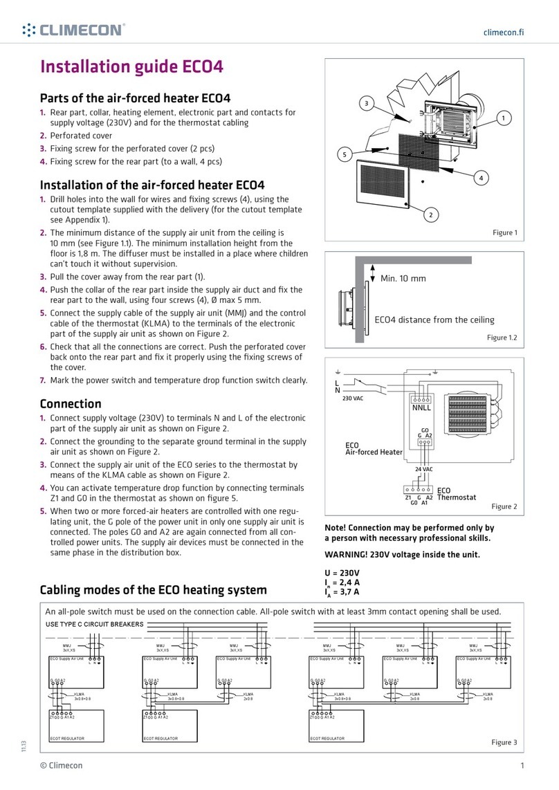
Parts of supply air unit ECO4
1. Rear part, collar, heating element, electronic part and contacts for
supply voltage (230V) and for the regulator cabling
2. Perforated cover
3. Fixing screw for the perforated cover (2 pcs)
4. Fixing screw for the rear part (to a wall, 4 pcs)
Installation of supply air unit ECO4
1. Drill holes into the wall for wires and fixing screws (4), using the
cutout template supplied with the delivery (for the cutout template
see Appendix 1).
2. The minimum distance of the supply air unit from the ceiling is 10
mm (see Figure 1.1).
3. Pull the cover away from the rear part (1).
4. Push the collar of the rear part inside the supply air duct and fix the
rear part to the wall, using four screws (4), Ø max 5 mm).
5. Connect the supply cable of the supply air unit (MMJ) and the control
cable of the regulator (KLMA) to the terminals of the electronic part
of the supply air unit as shown on Figure 4.
6. Check that all the connections are correct. Push the perforated cover
back onto the rear part and fix it properly using the fixing screws of
the cover.
Connection
1. Connect supply voltage (230V) to terminals N and L of the electronic
part of the supply air unit as shown on Figure 2.
2. Connect the grounding to the separate ground terminal in the supply
air unit as shown on Figure 2.
3. Connect the supply air unit of the RCL ECO series to the regulator by
means of the KLMA cable as shown on Figure 2.
4. You can activate temperature drop function by connecting terminals
Z1 and G0 in the regulator as shown on figure 5.
5. When two or more supply air units are controlled with one regulating
unit, the G pole of the power unit in only one supply air unit is con-
nected. The poles G0 and A2 are again connected from all controlled
power units. The supply air devices must be connected in the same
phase in the distribution box. Note! Connection work may be performed only by a
person with necessary professional skills.
WARNING! 230V voltage inside the unit.
1
2
3
5
4
NNLL
L
N
GO
G A2
Z1 G A2
G0 A1
24 VAC
230 VAC
ECO
Regulator
ECO
Supply Air Unit
ECO
10A
MMJ 3X1.5
10A
MMJ 3X1.5
KLMA 3X0.8+0.8 KLMA 3X0.8+0.8
1 ECO/room
ECO ECO
16A
MMJ 3X2.5
KLMA 3X0.8+0.8
KLMA 2X0.8
2 ECOa/room
KLMA 3X0.8+0.8
ECO
REGULATOR
ECO ECO
REGULATOR
REGULATOR
16A
MMJ 3X2.5
KLMA 3X0.8+0.8
KLMA 2X0.8 KLMA 2X0.8
3 ECOa/room
ECO4 distance from the ceiling
Min. 10 mm
Cabling modes of the ECO heating system
The protective automatic switches for cables must be type C.
Figure 1
Figure 1.2
Figure 2
Figure 3
11. 1 3
www.climecon.fi
© Climecon 2
Installation guide ECOT, regulator
Taking into use
1. Make sure that the connections are made correctly. Turn
on the 230V supply voltage coming to the supply air
unit. The display (7) will show the room temperature and
the LED (6) will light up. The factory setting of the regu-
lator is 21ºC (central point of the setting area) and if the
room temperature is lower, the led will turn red and the
heating will be switched on, otherwise a green led will
be illuminated.
2. When the value of the regulator is changed (± 3ºC from
the value of the central point) with the control knob (4),
you can see the new setting value on the display (7).
3. Changing the central point of the setting area to e.g.
24ºC. Open the cover (2) of the regulator and turn the
temperature control knob (4) up (extreme position). Re-
move jumper S3 and install it back to its position. The
new central point of the setting area will now be 24ºC.
4. The factory set accuracy of temperature adjustment is ±
0.5ºC. If you need to change the accuracy to ± 1ºC, remo-
ve jumper S2. Temperature drop from the setting value
of 3ºC...10ºC is adjusted from the knob (8).
5. The value of temperature drop is visible on the display
(7).
6. After you have made all the necessary changes, reinstall
the cover (2) and the system is ready for use.
Installation of the regulator:
1. Bring the cable intended for the regulator unit (KLMA) from the
supply air unit either to the instrument box (60 mm spacing bet-
ween holes) or directly to a surface-mounted ECO regulator.
2. Remove the cover (2) of the regulator from the rear part (1), using
e.g. a small screwdriver (clips at the upper and lower edge of the
thermostat).
3. Fix the rear part of the regulator either to the instrument box or
directly on the wall, using screws (3).
4. Connect the cables to the terminal block (5) as shown on Figure 2.
5. If the temperature drop function is taken into use, connect it as
shown on Figure 5.
6. After all the connection work, check the connections and reinstall
the cover of the regulator.
Parts of ECO regulator
1. Rear part
2. Cover
3. Fixing screw (to a wall, 2 pcs)
4. Temperature control knob
5. Terminal block
6. Signal LED
7. Temperature display
8. Control knob for changing the setting
value of temperature drop
9. Jumpers S2 and S3
2
1
4
3
5
6
7
8
9
Z1
GO (0V)
CLOSED = DROP
OPEN= NO DROP NPN CONDUCTS= DROP
NPN DOES NOT
CONDUCT= NO DROP
0V = DROP
10V = NO DROP
ECO-regulator ECO-regulator ECO-regulator
Z1
GO (0V)
Z1
GO (0V)
+
0/10V
-
Figure 4
Figure 5
Figure 6
1.
2.
Temperature drop alternatives of ECO regulator
www.climecon.fi
© Climecon 3
Installation instructions ECO4
4x
60
190
160
4x
1
3
5 6
2
4
Note! Connection work may be performed only by a person with necessary professional skills.
www.climecon.fi
© Climecon 4
Service instruction ECO4
1
3
5
2
4
6
Note! Connection work may be performed only by a person with necessary professional skills.
1
04x
Warning! 230V voltage inside.Turn o the supply voltage before maintenance.

Other Climecon Heater manuals

Climecon ECO1 User manual

Climecon

Climecon ECO1 User manual

Climecon ECO4 User manual

Climecon

Climecon ECO4 User manual

Climecon ECO-C User manual

Climecon

Climecon ECO-C User manual

Climecon ECO-W User manual

Climecon

Climecon ECO-W User manual

Climecon ECO2 User manual

Climecon

Climecon ECO2 User manual

Popular Heater manuals by other brands

L.B. White I17 Assembly and installation instructions

L.B. White

L.B. White I17 Assembly and installation instructions

Zibro SRE 178 E owner's manual

Zibro

Zibro SRE 178 E owner's manual

Trotec TDS 20 operating manual

Trotec

Trotec TDS 20 operating manual

CONVECTAIR Allegro 7300-C07 Installation notes

CONVECTAIR

CONVECTAIR Allegro 7300-C07 Installation notes

Heatstore HS2000X Installation and operating instructions

Heatstore

Heatstore HS2000X Installation and operating instructions

jbc PHBE instruction manual

jbc

jbc PHBE instruction manual

TZS First AUSTRIA FA-5565-3 instruction manual

TZS First AUSTRIA

TZS First AUSTRIA FA-5565-3 instruction manual

MALUX AW Series manual

MALUX

MALUX AW Series manual

Velleman Perel TC78011LCD user manual

Velleman

Velleman Perel TC78011LCD user manual

Glen GL 7011 user guide

Glen

Glen GL 7011 user guide

DeLonghi TRV Series Instructions for use

DeLonghi

DeLonghi TRV Series Instructions for use

Kroll MA59 instruction manual

Kroll

Kroll MA59 instruction manual

AMIRIDIS-SAVVIDIS UNITED ARC-8809 operating instructions

AMIRIDIS-SAVVIDIS

AMIRIDIS-SAVVIDIS UNITED ARC-8809 operating instructions

Jaga CLIMA CANAL HYBRID Mounting instructions

Jaga

Jaga CLIMA CANAL HYBRID Mounting instructions

RollSeal SW 100 installation manual

RollSeal

RollSeal SW 100 installation manual

Bimar S580.EU CPH-09 Instruction booklet

Bimar

Bimar S580.EU CPH-09 Instruction booklet

Magnum Heating Sol 300 installation manual

Magnum Heating

Magnum Heating Sol 300 installation manual

Viessmann VITOLADENS 300-T installation instructions

Viessmann

Viessmann VITOLADENS 300-T installation instructions

manuals.online logo
manuals.online logoBrands
  • About & Mission
  • Contact us
  • Privacy Policy
  • Terms and Conditions

Copyright 2025 Manuals.Online. All Rights Reserved.