Climecon ECO2 User manual

climecon.fi
© Climecon 1
Installation guide ECO2
Parts of the air-forced heater ECO2
1. Rear part, collar, heating element, electronic part and contacts for
supply voltage (230V) and for the thermostat cabling
2. Perforated cover
3. Fixing screw for the perforated cover (2 pcs)
4. Fixing screw for the rear part (to a wall, 4 pcs)
Installation of the air-forced heater ECO2
1. Drill holes into the wall for wires and fixing screws (4), using the
cutout template supplied with the delivery (for the cutout template
see Appendix 1).
2. The minimum distance of the supply air unit from the ceiling is
70 mm (see Figure 1.1). The minimum installation height from the
floor is 1,8 m. The diuser must be installed in a place where children
can’t touch it without supervision.
3. Remove the two fixing screws (3) of the perforated cover (2) and pull
the cover away from the rear part (1).
4. Push the collar of the rear part inside the supply air duct and fix the
rear part to the wall, using four screws (4), Ø max 5 mm.
5. Connect the supply cable of the supply air unit (MMJ) and the control
cable of the thermostat (KLMA) to the terminals of the electronic
part of the supply air unit as shown on Figure 2.
6. Check that all the connections are correct. Push the perforated cover
back onto the rear part and fix it properly using the fixing screws of
the cover.
7. Mark the power switch and temperature drop function switch clearly.
Connection
1. Connect supply voltage (230V) to terminals N and L of the electronic
part of the supply air unit as shown on Figure 2.
2. Connect the grounding to the separate ground terminal in the supply
air unit as shown on Figure 2.
3. Connect the supply air unit of the ECO series to the thermostat by
means of the KLMA cable as shown on Figure 2.
4. You can activate temperature drop function by connecting terminals
Z1 and G0 in the thermostat as shown on figure 5.
5. When two or more forced-air heaters are controlled with one ther-
mostat, the G pole of the power unit in only one supply air unit is
connected. The poles G0 and A2 are again connected from all con-
trolled power units. The supply air devices must be connected in the
same phase in the distribution box.
Note! Connection may be performed only by
a person with necessary professional skills.
WARNING! 230V voltage inside the unit.
U = 230V
In= 2,4 A
IA= 3,7 A
1
2
4
3
N
L
NNLL
L
N
GO
G A2
Z1 G A2
G0 A1
24 VAC
230 VAC
ECO
Thermostat
ECO
Air-forced Heater
ECO2 distance from the ceiling
Min. 70 mm
Cabling modes of the ECO heating system
An all-pole switch must be used on the connection cable. All-pole switch with at least 3mm contact opening shall be used.
Figure 1
Figure 1.2
Figure 2
Figure 3
11.13
ECOT REGULATOR
Z1G0 G A1 A2
ECO Supply Air Unit
G G0 A2
KLMA
3x0.8+0.8
L N
MMJ
3xX,XS
USE TYPE C CIRCUIT BREAKERS
ECOT REGULATOR
Z1G0 G A1 A2
ECO Supply Air Unit
G G0 A2
KLMA
3x0.8+0.8
L N
MMJ
3xX,XS
ECO Supply Air Unit
G G0 A2
L N
MMJ
3xX,XS
KLMA
2x0.8
ECOT REGULATOR
Z1G0 G A1 A2
ECO Supply Air Unit
G G0 A2
KLMA
3x0.8+0.8
L N
MMJ
3xX,XS
ECO Supply Air Unit
G G0 A2
L N
MMJ
3xX,XS
KLMA
2x0.8
ECO Supply Air Unit
G G0 A2
L N
MMJ
3xX,XS
KLMA
2x0.8
Figure 3
climecon.fi
© Climecon 2
Installation guide ECOT, thermostat
Commissioning
1. Make sure that the connections are made correctly.
Turn on the 230V supply voltage coming to the supply air
unit. The display (7) will show the room temperature and
the LED (6) will light up. The factory setting of the ther-
mostat is 21ºC (central point of the setting area) and if
the room temperature is lower, the led will turn red and
the heating will be switched on, otherwise a green led
will be illuminated.
2. When the value of the thermostat is changed (± 3ºC from
the value of the central point) with the control knob (4),
you can see the new setting value on the display (7).
3. Changing the central point of the setting area to e.g. 24ºC.
Open the cover (2) of the thermostat and turn the tem-
perature control knob (4) up (extreme position). Remove
jumper S3 and install it back to its position. The new
central point of the setting area will now be 24ºC.
4. The factory set accuracy of temperature adjustment is
± 0.5ºC. If you need to change the accuracy to ± 1ºC,
remove jumper S2.
5. Temperature drop from the setting value of 3ºC...10ºC
is adjusted from the knob (8). The value of temperature
drop is visible on the display (7).
6. After you have made all the necessary changes, reinstall
the cover (2) and the system is ready for use.
Installation of the thermostat:
1. Bring the cable intended for the thermostat unit (KLMA)
from the supply air unit either to the instrument box
(60 mm spacing between holes) or directly to a surface-
mounted ECO thermostat.
2. Remove the cover (2) of the thermostat from the rear part
(1), using e.g. a small screwdriver (clips at the upper and lower
edge of the thermostat).
3. Fix the rear part of the thermostat either to the instrument
box or directly on the wall, using screws (3).
4. Connect the cables to the terminal block (5) as shown on
Figure 2.
5. If the temperature drop function is taken into use, connect
it as shown on Figure 5.
6. After all the connection work, check the connections and
reinstall the cover of the thermostat.
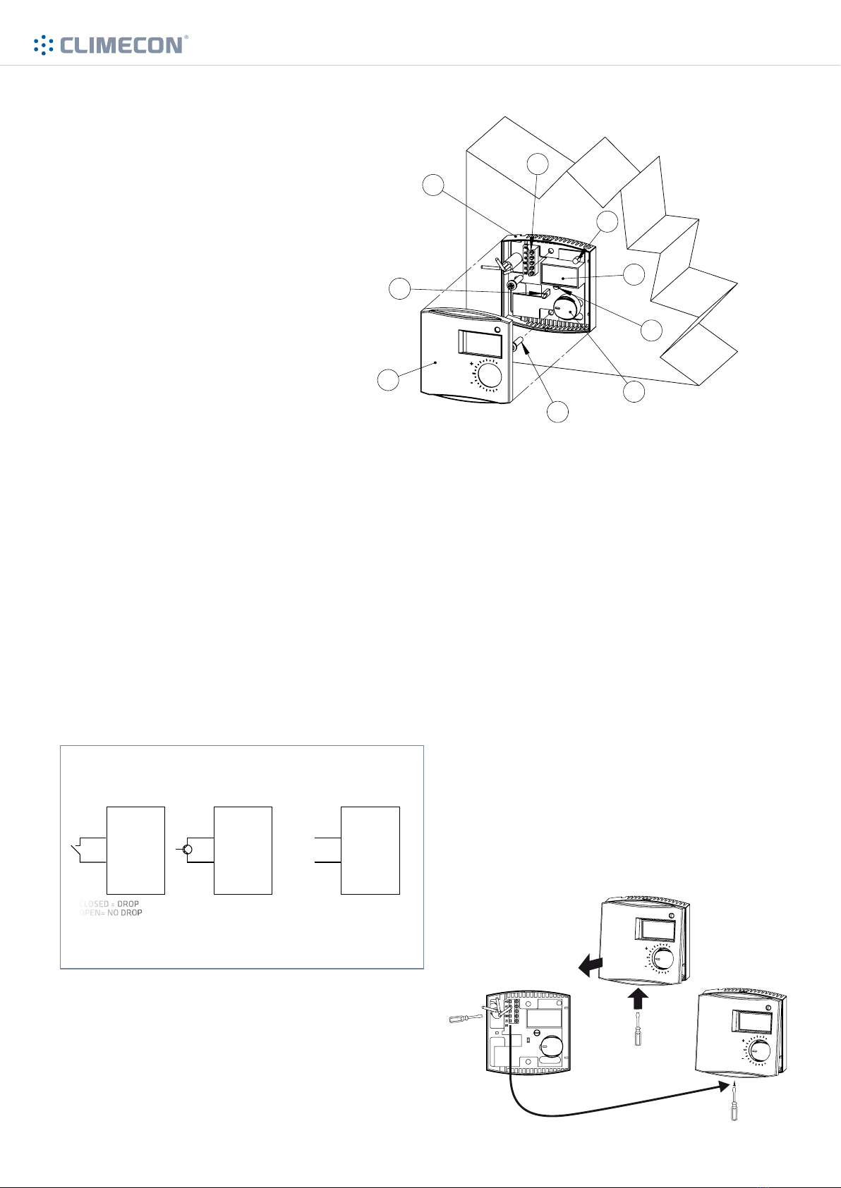
Parts of ECO thermostat
1. Rear part
2. Cover
3. Fixing screw (to a wall, 2 pcs)
4. Temperature control knob
5. Terminal block
6. Signal LED
7. Temperature display
8. Control knob for changing the setting
value of temperature drop
9. Jumpers S2 and S3
2
1
4
3
5
6
7
8
9
Z1
GO (0V)
CLOSED = DROP
OPEN= NO DROP NPN CONDUCTS= DROP
NPN DOES NOT
CONDUCT= NO DROP
0V = DROP
10V = NO DROP
ECO-thermostat ECO-thermostat ECO-thermostat
Z1
GO (0V)
Z1
GO (0V)
+
0/10V
-
Figure 4
Figure 5
Figure 6
1.
2.
Temperature drop alternatives of ECO thermostat

climecon.fi
© Climecon 3
Installation instructions ECO2
2x
1
3
5
2
4
Note! Connection work may be performed only by a person with necessary professional skills.

climecon.fi
© Climecon 4
Service instruction ECO2
1
3
5
2
4
6
Note! Connection work may be performed only by a person with necessary professional skills.
Warning! 230V voltage inside. Turn o the supply voltage before maintenance.
Note! Check also the condition of the supply air filter of the air handling unit.
1
02x
Other Climecon Heater manuals


Popular Heater manuals by other brands

Sears, Roebuck and Co.
Sears, Roebuck and Co. 583.90700 Assembly, operating instructions and parts list

ARDES
ARDES AR4R07M Instructions for use

Webasto
Webasto Thermo 90 S Operating and maintenance instructions

Nortek
Nortek Reznor FSE Series Installation, commissioning, servicing

Kooper
Kooper 2191600 User instructions

Cattara
Cattara 1000 W quick start guide

Argo
Argo MOOD operating instructions

Heat & Glo
Heat & Glo TIARAP-BK Installation and operation manual

THOMSON
THOMSON THRAYF011D instruction manual

Kerona
Kerona WKH-100A owner's manual

Clatronic
Clatronic HL 3651 instruction manual

Bromic Heating
Bromic Heating Tungsten Smart-Heat Installation, instruction and service manual


