Climer ECOFLEX EF02 User manual
INSTALLATION AND USER MANUAL
ECOFLEX
EF02
EF04

INSTALLATION AND USER MANUAL
ECOFLEX
V1REV3EN0622

INSTALLATION AND USER MANUAL
ECOFLEX
V1REV3EN0622
1. INTRODUCTION................................................................................................ 1
2. GENERAL INDICATIONS................................................................................... 1
3. TECHNICAL INFORMATION ............................................................................. 3
4. INSTALLATION STEPS ..................................................................................... 5
5. PLACING ECOFLEX.......................................................................................... 6
6. AIR CONNECTION............................................................................................. 7
7. HIDRAULIC CONNECTION ............................................................................... 8
8. ELECTRICAL CONNECTION............................................................................11
9. COMISSIONING. CONTROLLER......................................................................12
10. WARRANTY CONDITIONS...............................................................................22

INSTALLATION AND USER MANUAL
ECOFLEX
V1REV3EN0622

INSTALLATION AND USER MANUAL
ECOFLEX
1 V1REV3EN0622
1. INTRODUCTION
Thank you for buying a product manufactured by CLIMER TECHNOLOGY. This product, has
been manufactured according to the European Quality Standards, incorporates prime grade
materials and its correct working has been tested before it leaves our facilities.
Through this Installation and User Manual, you will be guide towards the correct and safety
installation of the product. It is necessary to carefully read this manual before making any
handling to avoid problems arising from the misuse of the product.
The company CLIMER TECHNOLOGY reserves the right to modify the information included in
this document at any time without prior notice.
2. GENERAL INDICATIONS
2.1. Safety notes
The incorrect or inappropriate use of this product could lead to hazardous situations, causing
damage or injuries to the user, third parties or even to the product itself or material goods.
-The installer has the responsibility to install the minimum safety devices (hydraulic and
electrical) set out in this Manual. In case of failure, the lack of any device may cause
burns or other injuries.
-The installer has the responsibility to inform the user about the function and placement
of the safety devices installed into the device and the installation.
-The water outlet temperature could reach 62 degrees. Do not touch the pipes while
the system is working to avoid any risk of burns.
2.2. Qualification of the installer
It is needed the technical staff have the official certification that accredits them as authorized
to handle coolants.
The installer must explain the user the application of the product and the use and
management of the unit, and he should provide the user all the documentation supplied
with the equipment.

INSTALLATION AND USER MANUAL
ECOFLEX
2 V1REV3EN0622
2.3. Package contents
The ECOFLEX system comprises the following components:
-ECOFLEX
-Silent-blocks
-User Manual
2.4. Indications about transport and unpacking the unit
The unit is supplied packed into a wooden pallet properly secured to prevent damage
during transport.
The material that CLIMER TECHNOLOGY uses to the packing are recyclables, so dispose it
in an appropriate container.
Use a forklift or hand pallet truck to transport the unit to the installation site, always
introducing the forks into the bottom of the pallet being careful not to damage the unit.
In case you identify any damage at the time of the reception of the unit, it is mandatory to
register it in the reception note of the transport company, and then, submit the complaint.
For this reason, it is recommended to make a thorough visual inspection of the goods before
signing the reception note.

INSTALLATION AND USER MANUAL
ECOFLEX
3 V1REV3EN0622
3. TECHNICAL INFORMATION
3.1. Operating Principle
Figure 1. Operating principle
DHW
Condenser:
Transfers
energy to water
Compressor
Evaporator: Extracts
energy from air
Expanssion valve

INSTALLATION AND USER MANUAL
ECOFLEX
4 V1REV3EN0622
3.2. Dimension drawings
Figure 2. Dimensions EF02
Figure 3. Dimensions EF04
Figure 4. Front and back connections
A
Power supply, 230 V/1PH/50 Hz
B
Condensate drain
C
Air intake
D
Air outlet
E
Hot water outlet, (EF02: 3/4”/ EF04: 1”)
F
Cold water inlet, (EF02: 3/4”/ EF04: 1”)
G
Temperature probe / Pump connection

INSTALLATION AND USER MANUAL
ECOFLEX
5 V1REV3EN0622
3.3. Technical data
4. INSTALLATION STEPS
Before starting the installation, check the availability of all the necessary components and tools:
-Drill
-Screwdriver
-Hydraulic installation components
-Electric installation components
Once it has been checked that it is available all the necessary components and tools, the
installer should follow the next steps:
1. Placing the ECOFLEX
2. Air connection
3. Hydraulic installation
4. Electric installation
5. Commissioning
Model
EF02
EF04
Energy efficiency class
A
A
Load profile
L
XL
Heating capacity range, W
1841 –1127
3680 –2270
Input power range, W
496 –407
990 –806
SCOP (14 °C)
2,91
3,01
Minimum air temperature, ºC
-5
Maximum water temperature, ºC
55
Refrigerant
R134a
Charge, g
950
1200
Power supply, V/ph/Hz
230 / 1 / 50
Air flow, m3/h
350
700
Maximum pressure drop (air), Pa
70
Air connection, mm
160
Mimimum water flow, L/h
250
485
Pressure drop heat exchanger, kPa
5
8
Water connection, inch
3/4
1

INSTALLATION AND USER MANUAL
ECOFLEX
6 V1REV3EN0622
5. PLACING ECOFLEX
The place where the system will be installed should allow an easy access to make maintenance
work or inspection.
Beside these factors, it is important to consider the following indications regards the installation
site:
-The system has been designed and manufactured for it indoors utilization.
-In case the system has to be placed outdoors, it must be protected against the adverse
weather conditions (direct solar radiation, rain, snow…)
-Try to place ECOFLEX as near as possible of the buffer tank.
-Installer must install the supplied Silent blocks to avoid the transmission of vibration.
The equipment allows the installation on floor or on wall. To do this, it has 4 holes to insert the
legs (supplied) or the supports to the brackets.
Figure 5. EF02 supports
Figure 6. EF04 supports
INSTALLATION AND USER MANUAL
ECOFLEX
7 V1REV3EN0622
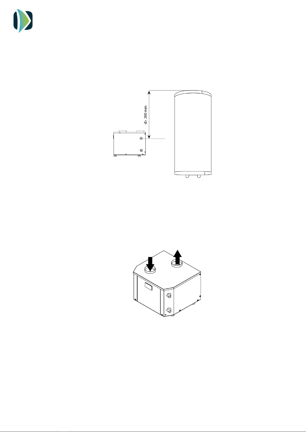
If the equipment is to be installed in the wall, be aware that a minimum distance between the
water outlet of the tank and the outlet of ECOFLEX must be observed to ensure a good
functioning of the pump and the equipment.
Figure 7. Minimum distance from ECOFLEX to the water outlet of the buffer tank.
6. AIR CONNECTION
ECOFLEX unit has two air connections located at the top cover of the system.
Figure 8. Outlet/intake air
Since the temperature of the exhaust air is lower than the intake air flow, the user can recover
this cold air to refresh a room. In this case, it is recommended to install a double duct, one to
the room and other to outdoors. Using a gate, the user can stop the air flow conducting it to
outdoors when cooling isn’t needed.
INSTALLATION AND USER MANUAL
ECOFLEX
8 V1REV3EN0622
IMPORTANT:
-Do not use flexible duct! Only smooth PVC pipe is allowed.
-Do not use anti-insect grid.
When the inlet and outlet ducting is needed, use only rigid smooth PVC tube.
The pressure drop in the whole air circuit (pipes and accessories) must be lower than the static
pressure of the system, 70 Pa.
In the following table is shown the allowed total pipe length (intake + exhaust). The equivalent
length of any accessory installed in the circuit must be subtract to the maximum allowed pipe
length:
Maximum length (PVC rigid pipe) 160 mm
14 m
Elbow 90º PVC 160 mm
3 equivalent meters
External grid
3 equivalent meters
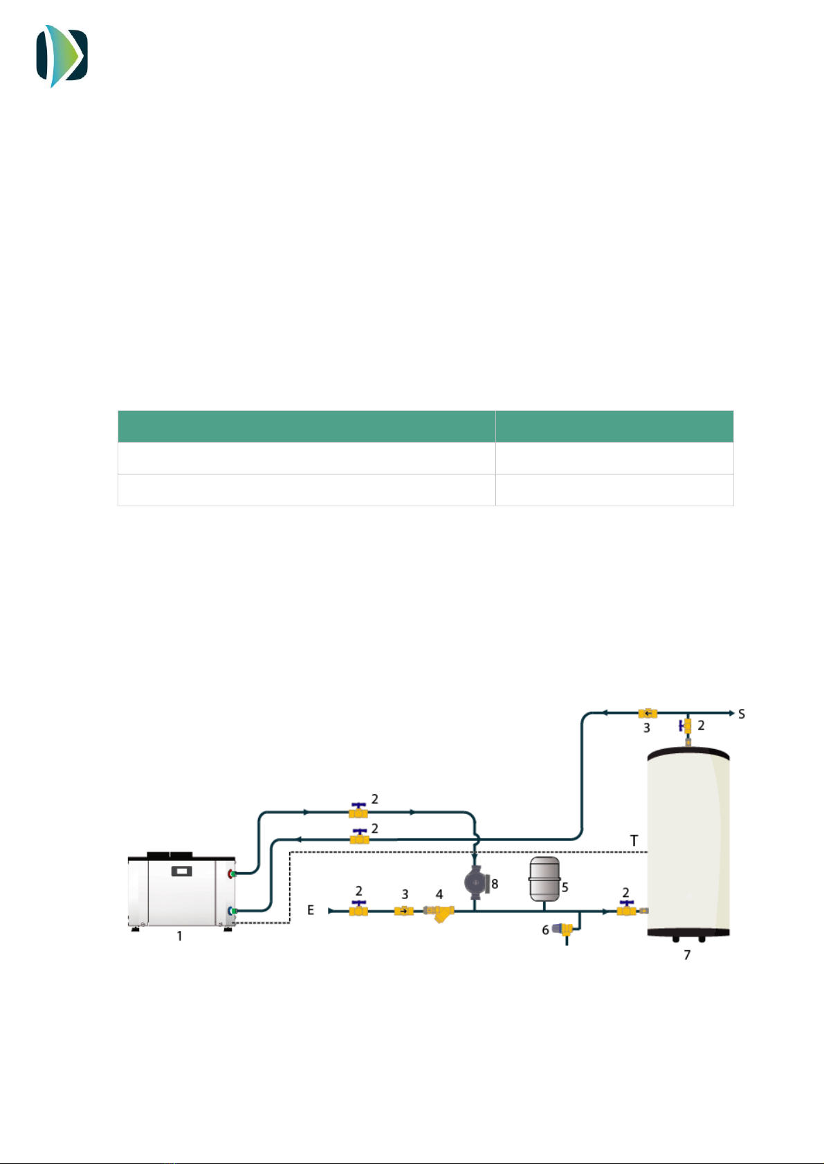
7. HIDRAULIC CONNECTION
The hydraulic connection depends on the existing buffer tank, if some type of connection for
the recirculation or coil is available.
The possible connections are detailed as follows:
Figure 9. ECOFLEX connection on storage tank with two outlets

INSTALLATION AND USER MANUAL
ECOFLEX
9 V1REV3EN0622
Figure 10. ECOFLEX connection on storage tank with a recirculation outlet
Figure 11. ECOFLEX connection, buffer tank with inner coil.
The installer must install the following components of the hydraulic circuit:
- ECOFLEX (1)
- Gate valve (2)
- Check Valve (3)
- Inclined filter (4)
- Expansion vessel (5)
- Safety valve (6)
- Storage tank (7)
- Pump (8)
- Pressure gauge (9)
- Red water inlet (E)
- DHW output (S)
- Inlet water filled coil (R)
- Probe connection (T)

INSTALLATION AND USER MANUAL
ECOFLEX
10 V1REV3EN0622
Once the hydraulic connections are made, purge the circuit to remove the air from the
installation.
In addition, it is necessary to install electrolytic sleeves in the water connections to prevent
galvanic corrosion in the pipes.
IMPORTANT:
- The water pipes must be at least 22 mm in diameter to avoid excessive losses in the circuit
- If the unit is to be installed on the wall, its height must not exceed half the storage tank.
7.1. Pump connection
For the choice of the pump, it is necessary to consider the pressure drop of the installed
pipe as well as the accessories (elbows, filters, valves ...). The following table shows the flow
rate to be circulated by the equipment and the pressure drop of the installed heat
exchanger:
7.2. Temperature probe connection
The equipment incorporates connected temperature probe. The installer must pass through
the indicated opening (Figure 4, G) and connect it to the buffer tank. The position of the
probe varies according to the type of buffer tank.
Follow the instructions in of the diagrams shown in Figures 9, 10 and 11.
Minimum flow, L/h
Pressure drop, kPa
EF02
250
5
EF04
485
8

INSTALLATION AND USER MANUAL
ECOFLEX
11 V1REV3EN0622
8. ELECTRICAL CONNECTION
The power supply of the system is 230 V/1/50 Hz.
8.1. Pump
The installer must connect the electrical connection of the pump to the terminal block inside
the ECOFLEX unit, as shown in the diagram above.
IMPORTANT: It is only permitted to connect a pump with a power supply of 230 V /1 ph/
50 Hz and 3 A maximum current.
8.2. Electrical heater
It is possible to control the operation of an electrical heater installed inside the tank. To do
this, the installer must connect the power supply to the controller through the terminals R.
IMPORTANT: It is only allowed to connect an electrical heater of 230 V/ 1ph /50 Hz and
1500 W maximum power.
PV: Photovoltaic connection
LPS: Low pressure switch
HPS: High pressure switch
NTC1: Water temperature probe
NTC2: Ambient temperature
probe
D: Display
VS:Solenoid valve
R: Electrical heater
K: Compressor (no relay in EF02)
F: Fan
230 VAC: Power supply
P: Pump
INSTALLATION AND USER MANUAL
ECOFLEX
12 V1REV3EN0622
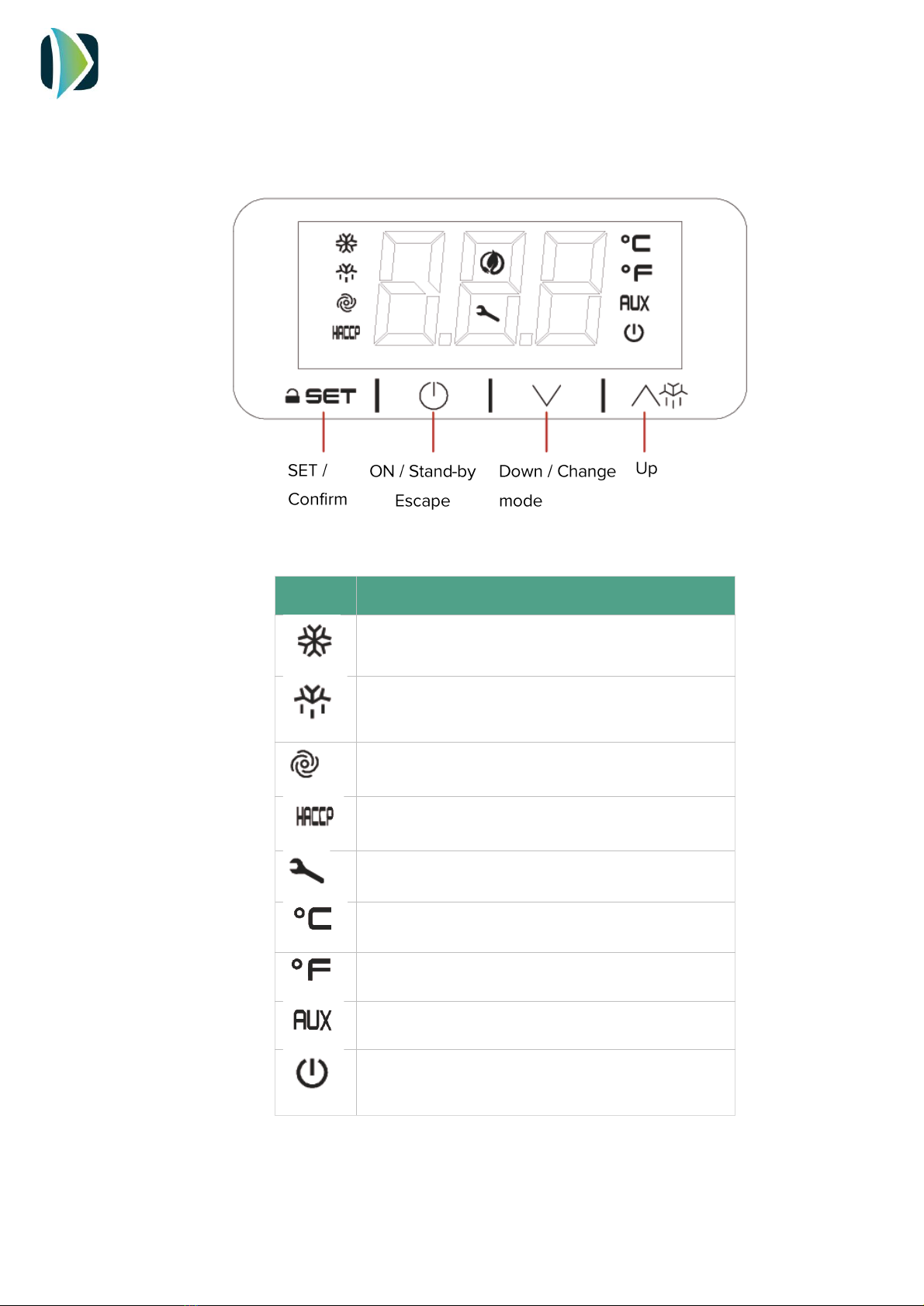
9. COMISSIONING. CONTROLLER.
9.1. User interface descriptionI
Symbol
Meaning when it lights
Compressor switched on
Defrost active
Fan switched on
Alarm active
Compressor working hours exceeded
Unit in ºC
Unit in ºF
Electric heater switched on
Stand by

INSTALLATION AND USER MANUAL
ECOFLEX
13 V1REV3EN0622
9.2. INSTALLATION - Switching on
After full installation of the water heater (power and water pipes connected) and after
the water heater tank is full of water, power can be turn ON.
9.3. Switching OFF
1. After filling the tank of water, connect
the mains plug to the mains supply.
The screen will show the
symbol.
2. Hold the key for 4 seconds. The
display will show the icons.
3. The screen will show the water
temperature.
To switch off the system, hold the
key for 4 seconds.
INSTALLATION AND USER MANUAL
ECOFLEX
14 V1REV3EN0622
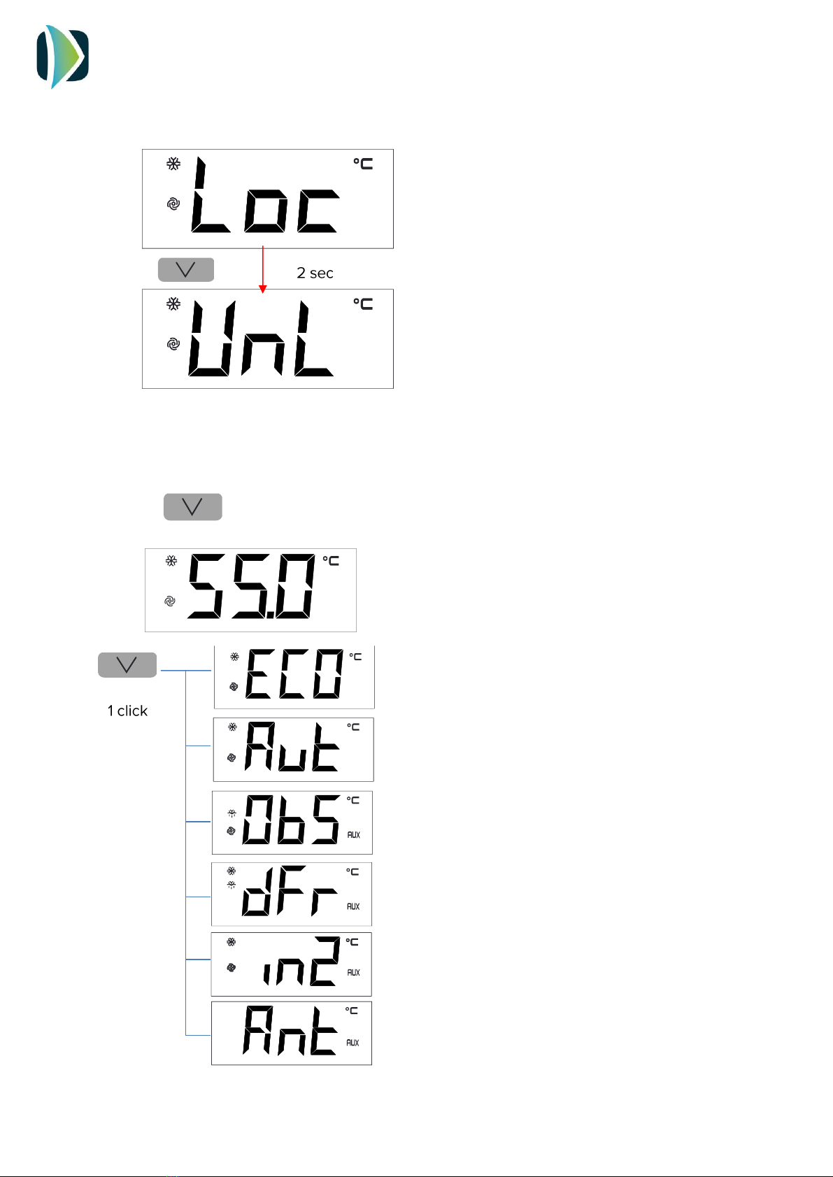
9.4. Unlocking the keypad
9.5. Displaying the operating mode
At first initial power ON, the product goes, by default, in Eco mode. By touching one time
the key, the controller will show the mode in operation in this moment.
When 30 have elapsed without the keys being
pressed, the display will show the ‘’ LOC’’
label and the keypad will lock automatically.
Touch any key until the screen shows UnL, to
unlock the keypad.
ECO Mode: Heating only by heat pump technology
Auto Mode: Heating by heat pump and electric heater
only if the water temperature falls drastically
OverBoost Mode: Simultaneously heating by heat pump
and electrical heater to achieve the temperature setpoint
as quickly as possible
Defrost: Defrost cycle active
Photovoltaics/ Timer: Automatic working due to the
existence of surplus energy from PV installation or Off-
Peak Rate
Antilegionella: Automatic disinfection by thermal shock
INSTALLATION AND USER MANUAL
ECOFLEX
15 V1REV3EN0622
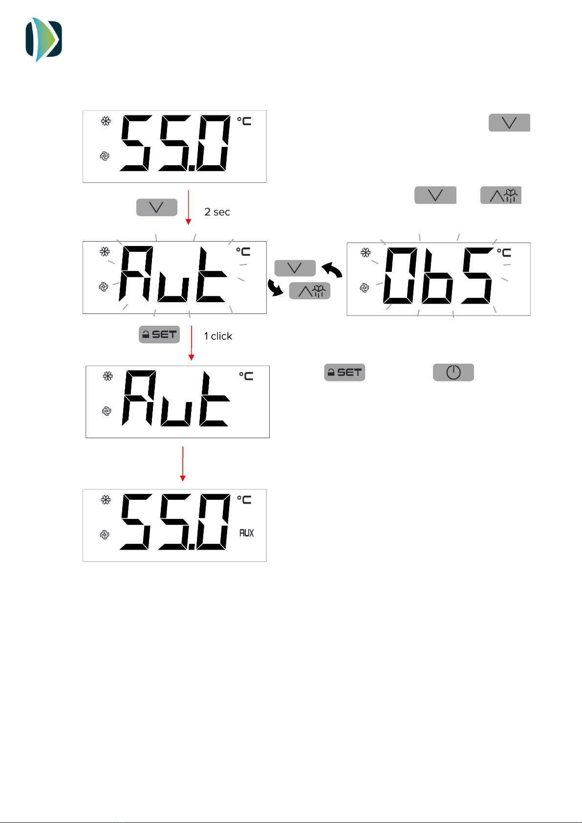
9.6. Changing operating mode
To change the operating mode, touch the
key for 2 seconds.
The screen will show blinking the selectable
operating modes. Use the and
keys to select the operating mode.
Touch to confirm or to cancel
The screen will show again the water temperature

INSTALLATION AND USER MANUAL
ECOFLEX
16 V1REV3EN0622
9.7. ECO Mode
ECO mode: Maximum savings. The system heats water only by heat pump technology.
This is the factory default mode.
Setting the ECO temperature setpoint
The water temperature set point in ECO mode can be changed with the SP1 parameter.
Touch key and select SP1. Touch
to confirm.
The display will show the programmed
temperature.
Touch or to select the desired
temperature.
Touch to confirm or to cancel.
This manual suits for next models
1
Table of contents
Other Climer Heat Pump manuals


Popular Heat Pump manuals by other brands

CTC Union
CTC Union GSi 12 Installation and maintenance manual

Samsung
Samsung CNH 4DB Series Technical data book

Carrier
Carrier 38YRA Product data

American Standard
American Standard allegiance 16 Application guide

DeLonghi
DeLonghi AWR-MTD2-XE Installation, operation and service manual

Lennox
Lennox LRP16G installation instructions


