Climer ECOHEAT EH500 User manual

INSTALLATION AND USER MANUAL
ECOHEAT
EH500

INSTALLATION AND USER MANUAL
ECOHEAT
V2REV2EN0822

INSTALLATION AND USER MANUAL
ECOHEAT
V2REV2EN0822
1. INTRODUCTION .............................................................................................................. 1
2. GENERAL INDICATIONS................................................................................................. 1
3. TECHNICAL INFORMATION............................................................................................ 2
4. INSTALLATION STEPS.................................................................................................... 5
5. PLACING ECOHEAT........................................................................................................ 5
6. AIR CONNECTION........................................................................................................... 6
7. HYDRAULIC CONNECTION ............................................................................................ 7
8. ELECTRICAL CONNECTION........................................................................................... 8
9. COMISSIONING. CONTROLLER..................................................................................... 9
10. WARRANTY CONDITIONS............................................................................................ 19

INSTALLATION AND USER MANUAL
ECOHEAT
1 V2REV2EN0822
1. INTRODUCTION
This product has been manufactured according to the European Quality Standards,
incorporates prime grade materials and its correct working has been tested before it leaves our
facilities.
Through this Installation and User Manual, you will be guide towards the correct and safety
installation of the product. It is necessary to carefully read this manual before make any
handling to avoid problems arising from the misuse of the product.
The company CLIMER TECHNOLOGY reserves the right to modify the information included in
this document at any time without prior notice.
2. GENERAL INDICATIONS
2.1. Safety notes
The incorrect or inappropriate use of this product could lead to hazardous situations, causing
damage or injuries to the user, third parties or even to the product itself or material goods.
-The installer has the responsibility to install the minimum safety devices (hydraulic and
electrical) set out in this Manual. In case of failure, the lack of any device may cause
burns or other injuries.
-The installer has the responsibility to inform the user about the function and placement
of the safety devices installed into the device and the installation.
-The water outlet temperature could reach 70 degrees. Do not touch the pipes while
the system is working to avoid any risk of burns.
2.2. Installer’s qualification
The installer must explain the user the application of the product and the use and
management of the unit, and he should provide the user all the documentation supplied
with the equipment.

INSTALLATION AND USER MANUAL
ECOHEAT
2 V2REV2EN0822
2.3. Package contents
The ECOHEAT system comprises the following components:
-ECOHEAT EH500
-Silent-Blocks
-User Manual
2.4. Indications about transport and unpacking the unit
The unit is supplied packed into a wooden pallet properly secured to prevent damage
during transport.
The material used to the packing are recyclables, so dispose it in an appropriate container.
Use a forklift or hand pallet truck to transport the unit to the installation site, always
introducing the forks into the bottom of the pallet being careful not to damage the unit.
In case you identify any damage at the time of the reception of the unit, it is mandatory to
register it in the reception note of the transport company, and then, submit the complaint.
For this reason, it is recommended to make a thorough visual inspection of the goods before
signing the reception note.
3. TECHNICAL INFORMATION
3.1. Operating Principle
Figure 1. Operating principle
Evaporator: Extracts
energy from the ambient
air
Compressor
Expanssion valve
Condenser:
Transfers energy
to the water
DHW
INSTALLATION AND USER MANUAL
ECOHEAT
3 V2REV2EN0822
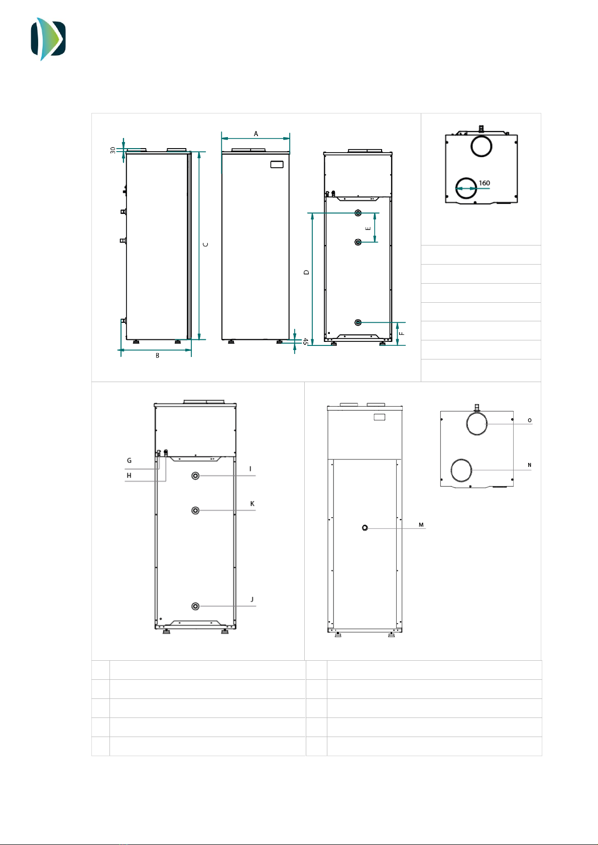
3.2. Dimension drawings
It is possible to remove the side and front casing access easily to any part of the system.
EH500 Dimensions (mm)
A: 696
B: 740
C: 2066
D: 1432
E: 325
F: 245
Back connections
Front connections
G
Power supply, 230 V/1PH/50 Hz
M
Temperature probe / electric heater
H
Condensate drain
N
Inlet air connection (160 mm)
I
Hot water outlet, 1‘’
O
Exhaust air connection (160 mm)
J
Cold water inlet, 1’’
K
Recirculation connection, 1‘’

INSTALLATION AND USER MANUAL
ECOHEAT
4 V2REV2EN0822
3.3. Technical data
Model
EH500
Cylinder
Capacity, L
500
Maximum operating pressure, bar
6
Heat pump data
Energy Efficiency Class
A
Load profile
XL
Heating capacity range, W
3122 –3907
Input power range, W
1082 –1145
SCOP (14 °C)
2.97
Minimum ambient temperature, ºC
-5
Maximum water temp. HP, ºC
60
Maximum water temp. electrical heater, ºC
70
Refrigerant / Charge, kg
R134a / 1.88
Electric data
Power supply, V/ph/Hz
230/1/50
Electric heater power, W
1500
Maximum absorbed power, W
2600
Air data
Intake/Exhaust connection, mm
160
Air flow, m3/h
700
Maximum pressure drop, Pa
70

INSTALLATION AND USER MANUAL
ECOHEAT
5 V2REV2EN0822
4. INSTALLATION STEPS
Before starting the installation, check the availability of all the necessary components and tools:
-Drill
-Screwdriver
-Hydraulic installation components
-Electric installation components
Once it has been checked that it is available all the necessary components and tools, the
installer should follow the next steps:
1. Placing the ECOHEAT
2. Hydraulic installation
3. Air connections
4. Electric installation
5. Commissioning
5. PLACING ECOHEAT
The place where the system will be installed should allow an easy access to make maintenance
work or inspection.
Air outlet of ECOHEAT is around 5-10 degrees below inlet temperature, so in case that the
exhaust air would not be ducted, the room temperature will be considerably reduced.
Beside these factors, it is important to consider the following indications regards the installation
site:
-The system has been designed and manufactured for it indoors utilization. Install the
system in a dry, frost-free room at a minimum temperature of 5 ºC. The surface on which
it is to be installed must be able to support the total load of the system.
-As the equipment may cause vibrations or noise, it is recommended to install away from
resting places.
-Installer must install the supplied Silent blocks to avoid the transmission of vibration.
INSTALLATION AND USER MANUAL
ECOHEAT
6 V2REV2EN0822
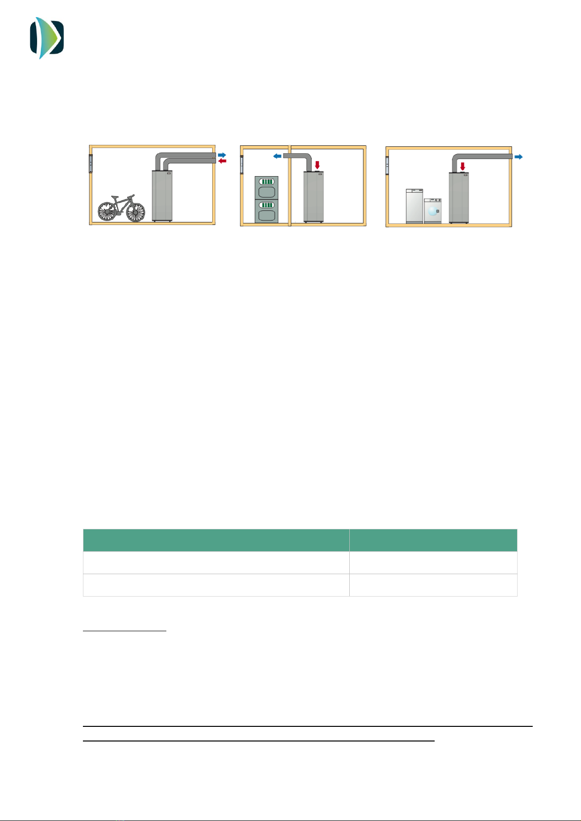
6. AIR CONNECTION
Ecoheat unit has two air connections located at the top cover of the system.
There are different installations possibilities:
Since the temperature of the exhaust air is lower than the intake air flow, the user can recover
this cold air to refresh a room. In this case, it is recommended to install a double duct, one to
the room and other to outdoors. Using a gate, the user can stop the air flow conducting it to
outdoors when cooling isn’t needed.
IMPORTANT:
-Do not use flexible duct! Only smooth PVC pipe is allowed.
-Do not use anti-insect grid.
When the inlet and outlet ducting is needed, use only rigid smooth PVC tube.
The pressure drop in the whole air circuit (pipes and accessories) must be lower than the static
pressure of the system, 70 Pa.
In the following table is shown the allowed total pipe length (intake + exhaust). The equivalent
length of any accessory installed in the circuit must be subtract to the maximum allowed pipe
length:
Maximum length (PVC rigid pipe) 160 mm
17 m
Elbow 90º PVC 160 mm
3 equivalent meters
External grid
2 equivalent meters
SUCTION FILTER
The system includes in the air intake a filter for the protection of all the elements of the
refrigeration circuit. This filter should be checked every 6 months to verify that is has not been
clogged. To do this, remove the filter from the suction duck and check if the channels allow air
passage. Otherwise, wash it with water or replace with a new one.
If you notice that the system does no heat up, check the condition of the filter. A clogged filter
affects the life-cycle performance and hot water production of the system.
INSTALLATION AND USER MANUAL
ECOHEAT
7 V2REV2EN0822
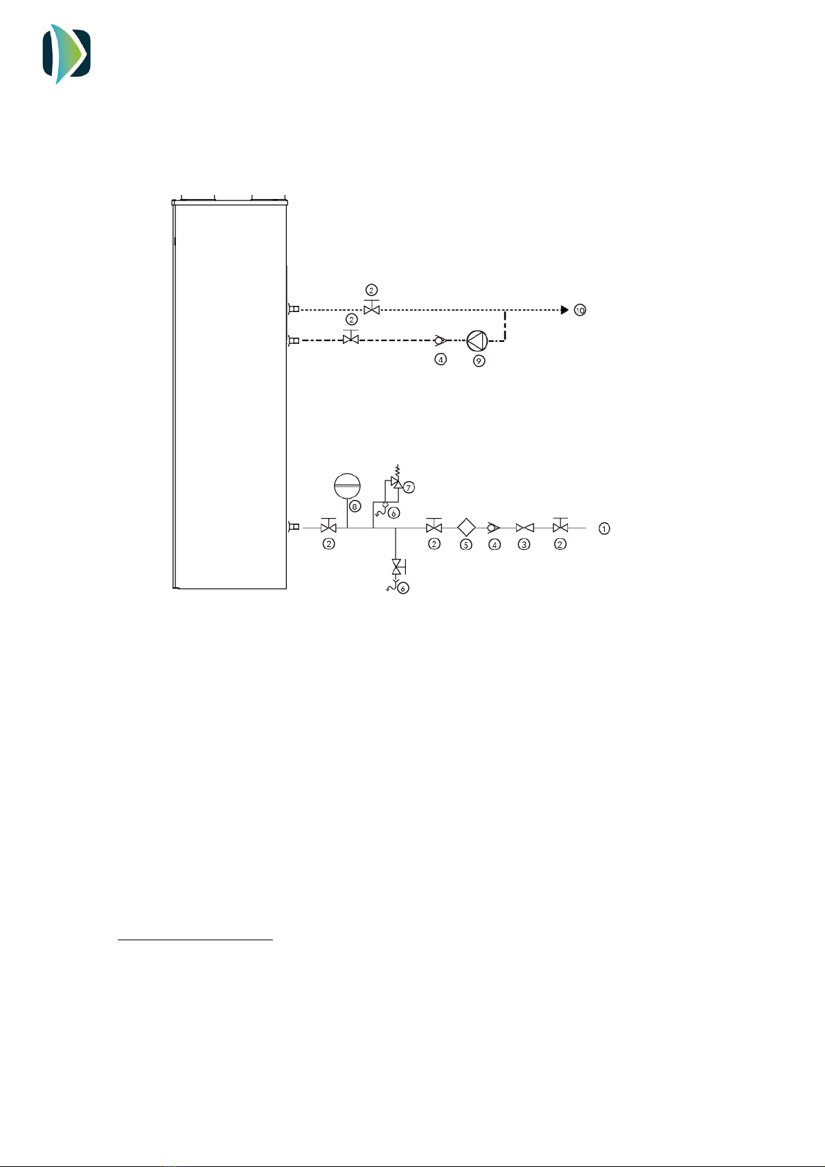
7. HYDRAULIC CONNECTION
The hydraulic connections are shown in the following scheme:
The installer must install the following components of the hydraulic circuit:
-Cold water inlet (1)
-Ball valves (2)
-Pressure reducing valve (3)
-Non-return valve (4)
-Lined Filter Strainer (Y Type) (5)
-Drain (6)
-Safety valve (7)
-Expansion vessel (8)
-Recirculation pump (9)
-DHW outlet (10)
Once the hydraulic connections are made, vent the circuit to avoid the air inside the installation.
CONDENSATE DRAIN
The condensation in the evaporator could produce a constant water flow that has to be drained
properly. Connect the condensate drain to the wastewater network making a siphon.
Ensure that water can flow freely.
INSTALLATION AND USER MANUAL
ECOHEAT
8 V2REV2EN0822
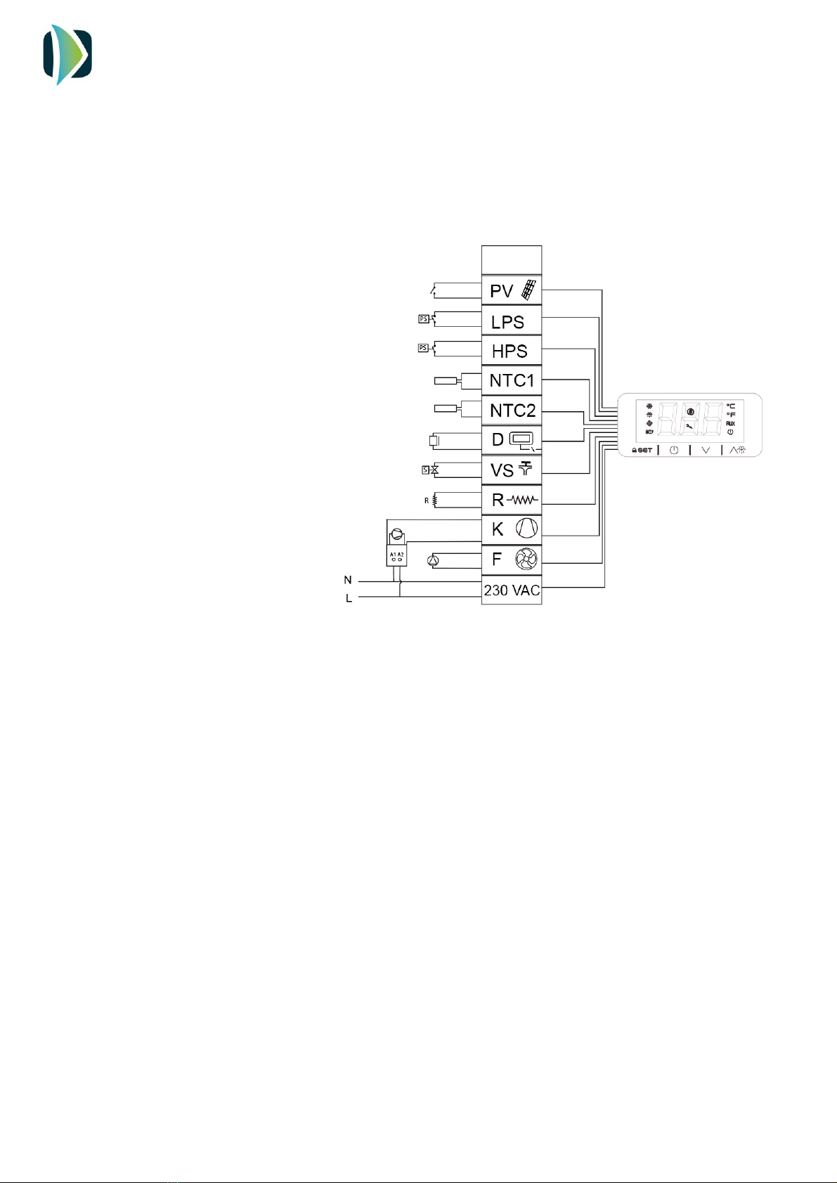
8. ELECTRICAL CONNECTION
The power supply of the system is 230 V/1/50 Hz. The power line must be protected by a circuit
breaker of 2 poles / 16 A.
The connection scheme is shown in the picture above.
PV: Photovoltaic connection
LPS: Low pressure switch
HPS: High pressure switch
NTC1: Water temperature probe
NTC2: Outdoor temperature probe
D: Display
VS: Solenoid valve
R: Electrical heater
K: Compressor
F: Fan
230 VAC: Power supply
A1-A2: Relay
INSTALLATION AND USER MANUAL
ECOHEAT
9 V2REV2EN0822
9. COMISSIONING. CONTROLLER.
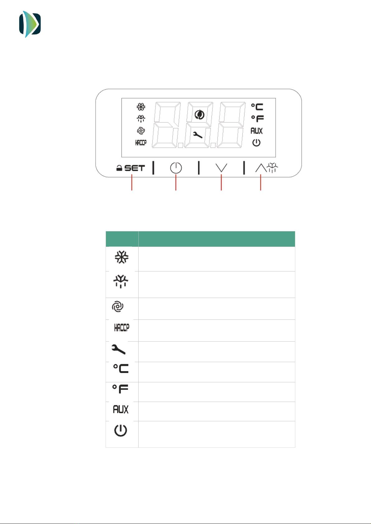
9.1. User interface description DE SC R IP TI
Symbol
Meaning when it lights
Compressor switched on
Defrost active
Fan switched on
Alarm active
Compressor working hours exceeded
Unit in °C
Unit in °F
Electric heater switched on
Stand by
SET /
Confirm
ON / Stand-by
Escape
Down / Change
mode
Up

INSTALLATION AND USER MANUAL
ECOHEAT
10 V2REV2EN0822
9.2. INSTALLATION- Switching on
After full installation of the water heater (power and water pipes connected) and after the
water heater tank is full of water, power can be turn ON.
9.3. Switching OFF
4 sec
1. After filling the tank of water, connect
the mains plug to the mains supply. The
screen will show the symbol.
2. Hold the key during 4 seconds.
The display will show the icons.
3. The screen will show the water
temperature.
4 sec
To switch off the system, hold the
key for 4 seconds.

INSTALLATION AND USER MANUAL
ECOHEAT
11 V2REV2EN0822
9.4. Unlocking the keypad
9.5. Displaying the operating mode
At first initial power ON, the product goes, by default, in Eco mode. By touching one time
the key, the controller will show the mode in operation in this moment.
When 30 have elapsed without the keys being
pressed, the display will show the ‘’ LOC’’
label and the keypad will lock automatically
Touch any key until the screen shows UnL, to
unlock the keypad
2 sec
1 click
ECO Mode: Heating only by heat pump technology
Auto Mode: Heating by heat pump and electric heater
only if the water temperature falls drastically
OverBoost Mode: Simultaneously heating by heat
pump and electrical heater to achieve the temperature
setpoint as quickly as possible
Defrost: Defrost cycle active
Photovoltaics/ Timer: Automatic working due to the
existence of surplus energy from PV installation or Off
Peak Rate
Antilegionella: Automatic disinfection by thermal shock
INSTALLATION AND USER MANUAL
ECOHEAT
12 V2REV2EN0822
9.6. Changing operating mode
2 sec
To change the operating mode, touch the
key for 2 seconds.
The screen will show blinking the selectable
operating modes. Use the and
keys to select the operating mode.
1 click
Touch to confirm or to cancel.
The screen will show again the water temperature.

INSTALLATION AND USER MANUAL
ECOHEAT
13 V2REV2EN0822
9.7. ECO Mode
ECO mode: Maximum savings. The system heats water only by heat pump technology.
This is the factory default mode.
Setting the ECO temperature setpoint
The water temperature set point in ECO mode can be changed with the SP1 parameter.
1 click
1 click
1 click
Touch key and select SP1. Touch
to confirm.
The display will show the programmed
temperature.
Touch or to select the desired
temperature.
Touch to confirm or to cancel.
INSTALLATION AND USER MANUAL
ECOHEAT
14 V2REV2EN0822
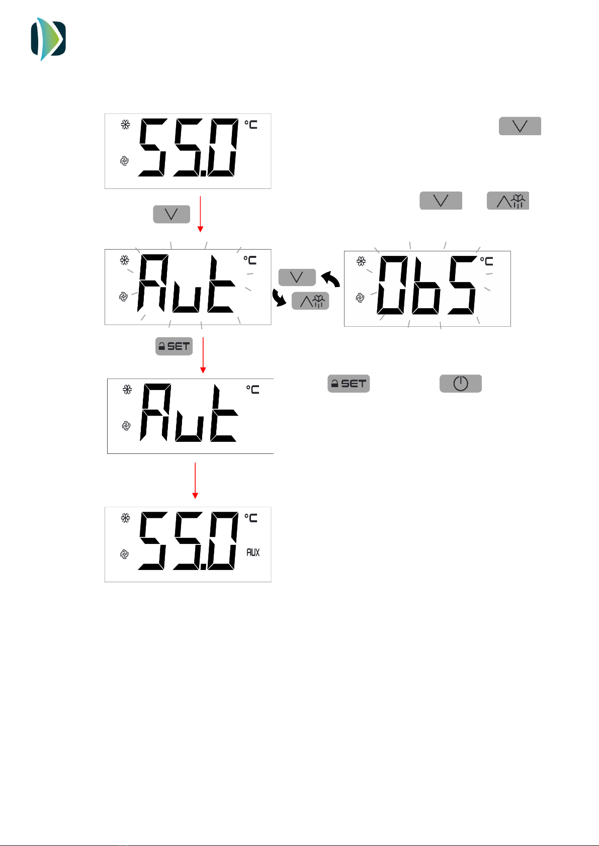
9.8. AUTO Mode
It maintains a steady temperature by the heat pump and only use the electrical heater if the
temperature falls drastically.
Setting the AUTO temperature setpoint
The water temperature set point in AUTO mode can be changed with the SP2 parameter.
1 click
1 click
1 click
Touch key and select SP2. Touch
to confirm.
The display will show the programmed
temperature.
Touch or to select the
desired temperature.
Touch to confirm or to
cancel.

INSTALLATION AND USER MANUAL
ECOHEAT
15 V2REV2EN0822
9.9. OVERBOOST Mode
Select this mode to achieve a fast heating by using simultaneously heat pump and electric
heater.
This mode Works as a rapid heating. Once the setpoint temperature is reached, the system
returns to the initial mode.
-If Overboost mode is switched on when the system Works from ECO mode: The
system heats the water up to SP1, and then returns to ECO again
-If Overboost mode is switched on when the system Works from Auto mode: The
system heats the water up to SP2, and then returns to Auto again
When Overboost mode is active, the display automatically changes showing the water
temperature and Obs.
Cancelling the Overboost Mode
2 sec
2 sec
Touch for 2 seconds, Obs will blink on
the screen
Touch for 2 seconds again, Obs will
blink faster
Touch and the mode will be changed for
the initial mode.

INSTALLATION AND USER MANUAL
ECOHEAT
16 V2REV2EN0822
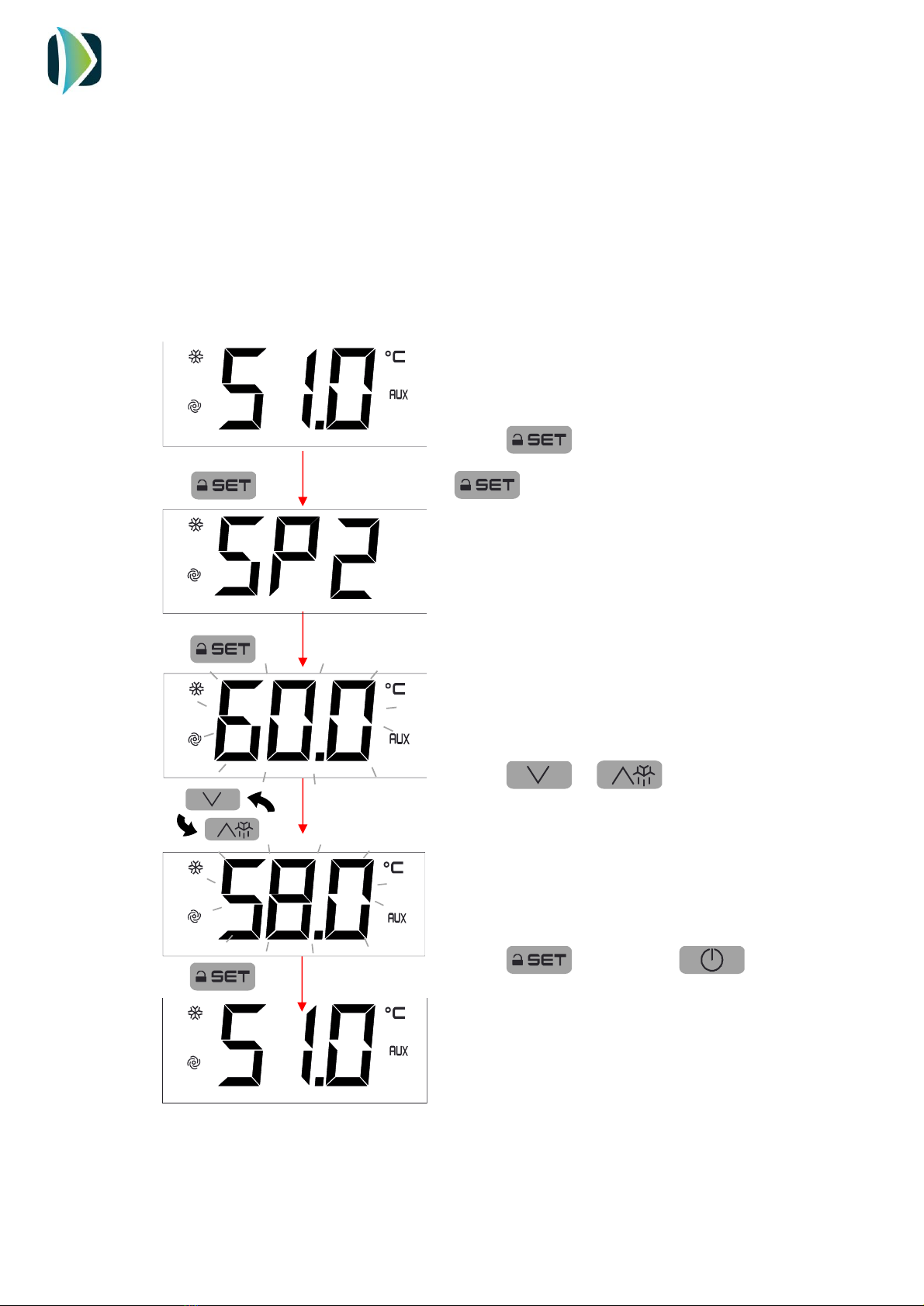
Parameter SP3 allows to set the minimum temperature that Overboost can be activated.
To change it value, follow the procedure:
1 click
1 click
1 click
Touch and select with and
SP3. Touch to confirm.
The display will show the programmed
temperature.
Touch or to select the
desired temperature.
Touch to confirm or to
cancel.

INSTALLATION AND USER MANUAL
ECOHEAT
17 V2REV2EN0822
9.10. PHOTOVOLTAIC INPUT
Working on this mode, the system automatically heats the water due to electric energy
surplus or by Off Peak rate.
The parameters of this mode can only be changed by the Installer’s Menu.
Contact with the technician for more information.
The system can be combined with and Photovoltaic Inverter to take advantage of the surplus
energy generated by the panels, by forcing the system working and storing this energy in
useful hot water.
The system has in the electric boar two terminals to connect a zero-voltage contact.
When the contact is closed, the system automatically changes to Photovoltaic mode and the
heat pump and electric heater work to achieve the programmed temperature. When the
contact is opened, the system returns to the previous mode.
This contact can be also used for Off Peak Rates. To do it, connect into the contact a timer
with a zero-voltage output.
9.11. Displaying/deleting compressor functioning hours
1 click
1 click
Display compressor functioning hours
Delete compressor functioning
hours
Touch the UP or
DOWN key to set
“149”
Table of contents
Other Climer Heat Pump manuals


Popular Heat Pump manuals by other brands

CHAFFOTEAUX
CHAFFOTEAUX ARIANEXT-R PLUS 12 kW Technical instructions

Gree
Gree FLEXX24HP230V1BH owner's manual

AERMEC
AERMEC NRW 27 Technical and Installation Booklet

Fujitsu
Fujitsu Waterstage WS G140DC6 Series Maintenance Document

Atlantic
Atlantic Loria 6000 R32 installation manual

Danfoss
Danfoss DHP-H user manual


