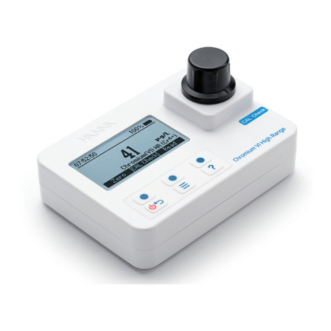
CLIMIA CMG 100 User manual

CLIMIA
Humidity measuring unit CMG 100
Operating manual
Edition 1.0
English


3
Humidity measuring unit CMG 100
Content
Carefully read this operating manual prior to commissioning/using the units!
This operating manual is a translation of the German original.
This manual is an integral part of the unit and must always be kept in the vicinity of the installation
locationor on the unit itself.
Subject to modications. No liability accepted for errors or misprints!
1.0 Safety information 4
2.0 Guarantee 5
3.0 Intended use 5
4.0 Environmental protection and recycling 5
5.0 Transportation and packaging 5
6.0 Operation 6
7.0 Commissioning 7
8.0 Use 7-9
9.0 Care, cleaning and maintenance 9
10.0 Scope of delivery 9
11.0 Technical data 10
12.0 Air dehumidication 11-13

4
CLIMIA
General safety notes
Carefully read the operating manual
before placing the unit in service
for the first time. It contains useful
tips and notes as well as hazard
warnings to prevent injury or
material damage. Failure to follow
the directions in this Manual can
endanger persons, the environment
and the equipment itself and will
void any claims for liability.
•The product is not a toy. Keep it
away from children and pets.
•Do not leave the packaging
material carelessly lying around.
This could become hazardous to
children.
•Protect the product from extreme
temperatures, direct sunlight,
strong vibrations, excessive
humidity, moisture, flammable
gases, vapours and solvents.
•Do not expose the product to
mechanical stress.
•If safe use is no longer possible,
take the product out of service
and secure it against accidental
use. Safe use is no longer
guaranteed if the product:
- exhibits visible damage,
- no longer functions properly,
- has been stored for a
longer period of time under
unfavourable environmental
conditions or
- has been subjected to
considerable transport stresses.
•Handle the product with care. It is
damaged by bumps, impacts or
falling from even a low height.
•Consult a professional if you have
any doubts about the operation,
safety or connection of the
product.
•Have maintenance, adaptation
and repair work carried out
exclusively by a specialist or a
specialist workshop.
•If you still have questions that are
not answered in this operating
manual, please contact our
technical customer service or
other professionals.
1.0 Safety information
Battery/rechargeable battery
•When inserting the battery /
rechargeable battery, ensure
that the polarity is correct.
•Remove the battery /
rechargeable battery if you are
not going to use the unit for a
long time to avoid damage due
to discharge. Discharging or
damaged rechargeable batteries
can cause acid burns if they
come into contact with the
skin. You should therefore wear
protective gloves when handling
damaged batteries/rechargeable
batteries.
•Keep rechargeable batteries out
of the reach of children. Do not
leave rechargeable batteries
lying around as they could be
swallowed by children or pets.
•Do not disassemble, short circuit
or dispose of rechargeable
batteries in re. Never attempt
to charge non-rechargeable
batteries. There is a risk of
explosion!
The following notes must be
observed in full:
People and product
•If the unit is brought from a
cold to a warm environment,
condensate water may form
inside the unit. This can lead to
incorrect measurement results.
Before using the unit, let it rest
for a while until it has adapted to
the new ambient air.
•The user is responsible for
themeasurement results
of this unit. We do not
guarantee theaccuracy of
themeasurement results, nor
do we accept responsibility for
them. Under no circumstances
do we accept responsibility
for damage caused by the
application of themeasurement
results.

5
Humidity measuring unit CMG 100
The units are shipped in sturdy
transport packaging. Check the
unit immediately after delivery and
make a note of any damage (please
take photos of the damage) or
missing parts on the delivery note.
Inform the forwarding agent and
contractual partner.
Please keep the packaging safely for
any returns.
Claims under guarantee made at a
later date will not be accepted.
5.0 Transportation and
packaging
3.0 Intended use
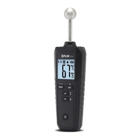
The product is used for non-invasive,
digital humidity measurement. It
is ideal for measuring the moisture
content of concrete, wood and
other building materials. The unit
can be used to check whether the
surface is ready for painting or
coating. Large surfaces can also be
measured quickly and effectively
using the signal function. The user
can concentrate on the object
being measured without having to
constantly read the measured values
on the display. The unit beeps when
the humidity level exceeds the limit.
The limit value is adjustable. The unit
offers a wide measuring spectrum
with a measuring depth of about
20 - 40 mm and has a display for
min/max values and for low battery.
The unit is powered by a 9 V block
battery. It also has an automatic
switch-off function.
For safety and approval reasons, you
must not convert and/or modify
the product. If you use the product
for purposes other than those
described above, the product may
be damaged. In addition, improper
use can cause hazards such as short-
circuits, fire, etc. Read the operating
manual carefully and keep it in a
safe place. Only pass the product on
to third parties together with the
operating manual.
The product complies with the legal,
national and European requirements.
All company names and product
designations contained herein
are trademarks of their respective
owners. All rights reserved.
2.0 Guarantee
As a prerequisite for any warranty
claims to be considered, it is
essential that the ordering party or
its representative completes and
returns the "certificate of guarantee"
to Climia Intakt GmbH at the time
when the units are purchased and
commissioned.
The guarantee conditions are
listed in the "General terms
and conditions of business and
supply". Furthermore, only the
parties to a contract can conclude
special agreements beyond these
conditions. In this case, contact
your contractual partner
in the first instance.
Disposal of packaging
All products are packed for
transport in environmentally
friendly materials. Make a valuable
contribution to reducing waste
and sustaining raw materials. Only
dispose of packaging at approved
collection points.
Disposing of the units and their
components
Only recyclable materials are used
in the manufacture of the units and
components.
Help protect the environment
by ensuring that the units or
components (for example batteries)
are not disposed of in household
waste, but only in accordance
with local regulations and in an
environmentally safe manner, e.g.
using authorised disposal and
recycling specialists or council
collection points.
4.0 Environmental
protection and
recycling

6
CLIMIA
Fig. 1 Humidity measuring unit
1
5
4
6
8
73
2
Controls
Legend
1 Humidity sensor
2 LC Display
3 DOWN key
4 SET key
5 MEAS key
6 On/O key
7 UP key
8 Battery compartment (on the back)
6.0 Operation
Fig. 2 LC Display
910
11
12
13
14
15
18
17
16
Legend
9 Low battery indicator
10 “HOLD” data storage symbol
11 “DRY”status symbol
12 “RISK” status symbol
13 “WET”status symbol
14 “MIN”symbol
15 Min. humidity level
16 Max. humidity level
17 “MAX”symbol
18 Current humidity level

7
Humidity measuring unit CMG 100
Inserting and replacing batteries
The humidity measuring unit is
powered by a 9 V block battery.
When delivered, the battery
is enclosed separately. It must
be inserted into the humidity
measuring unit.
To insert the battery, proceed as
follows:
•
Using a suitable screwdriver,
remove the battery compartment
cover from the back of the
measuring unit
•
Insert a new 9 V block battery
into the battery compartment [8],
observing the correct polarity.
Make sure that the contacts of
the unit are well seated
•
Replace the battery compartment
cover and screw it back in place
•
Replace the battery when the low
battery indicator [9] lights up on
the LC display
•
To change the battery, proceed
as described above. However,
remove the used battery from
the contacts and the battery
compartment before inserting a
new one.
7.0 Commissioning
NOTE
Ensure that the humidity
measuring unit is switched o
before changing the battery.
General notes before starting
measuring
•
The displayed humidity level is
an average value determined by
the moisture on the outer surface
as well as inside the material.
If there is any visible surface
moisture or water, wipe it o
and allow the surface to dry for
a few minutes before starting
themeasurement
•
Other factors can also inuence
the measurement. Before the
measurement, the corresponding
surface must be cleaned of any
paint residues, dust, etc
•
Before measurement, the
measuring point must be cleared
of impurities (e.g. dust and other
loose components).
•
If the measured material contains
metal (e.g. nails, screws, leads,
pipes, etc.) and this is located in
the measuring eld of the sensor,
the measured value increases
abruptly due to strong reections
•
If the spherical head is held in
corners (e.g. tile joints or window
niches), the measured value is
generally higher because there is
more substance in the scattering
eld of the measuring head
•
There must be a distance of more
than 8 to 10 cm from the corner
•
Hold the measuring unit at its
outermost end as far away as
possible from the ball head of
the humidity sensor [1] to avoid a
possible inuence of humidity by
your hand on the measured value
8.0 Use
•
The measuring unit is not suitable
for measuring metal or other
highly conductive materials.
If there is metal enclosed in
the material (e.g. nails, screws,
cables, pipes, etc.) in the sensor's
measuring range, the measured
values increase considerably
•
If the humidity sensor [1] is
placed in a corner of the wall,
themeasured values may be
higher because there are two or
three surfaces in the measuring
range.
Keep a minimum distance of 8
to 10 cm from other surfaces to
avoid interference
•
Place the humidity sensor [1] on
smooth surfaces. Rough surfaces
lead to inaccurate measurement
results
•
The measuring depth of the
unit ranges from 20 to 40 mm.
Depending on the density of
thematerial, a measurement
of the inner core may not be
possible. If the material is less
than 2 cm thick, the measured
value of the humidity level may
be inaccurate due to adjacent
material
•
The humidity sensor [1] must be
held at right angles directly to
thesurface to be measured
•
The density of the measured
material plays an important role
for the measurement result.
Themeasured value increases
with the respective density
•
An important area of application
for this unit is comparative
measurements, where the
measured value is compared with
a reference value. Thereference
value is determined by

8
CLIMIA
Switching on and o
•
To switch on, press the on/o
key [6] when the measuring unit
is switched o. To switch o,
press the on/o key [6] when
themeasuring unit is switched
on.
Humidity level measurement
•
Switch on the measuring unit by
pressing the on/o key [6]
•
The measuring unit must be
calibrated each time it is switched
on. Hold the measuring unit in
the air for calibration so that
thehumidity sensor [1] does not
touch any objects. The minimum
distance from any surface or
your hand to the ball head of the
humidity sensor [1] should be 8
to 10 cm
NOTE
If you have calibrated
the measuring unit for a
measurement, do not change
the position of the hand in
thesubsequent measurement.
Measurement calibration and
measurement must be carried
out with the same hand position,
because a change in the position
of the hand, relative to the ball
head of the humidity sensor [1],
leads to measuring errors.
•
The calibration must always
be carried out again after each
new switch-on as well as each
change of the measuring point or
themeasured object!
•
Hold the ball head of
thehumidity sensor [1] at right
angles to the surface.
The display shows the measured
value (current humidity level
[18]).
•
Move the measuring unit to take
measurements of a larger surface.
The LC display should show the
current measured value as well as
the maximum [16] and minimum
[15] measured values.
•
If necessary, press the MEAS
key [5] to freeze a value on
thedisplay.“HOLD”[10] appears
on the display in addition
to thelast measured value.
If the“HOLD” mode is not
terminated by pressing the MEAS
key [5], the measured values
are shown on the LC display
for another 30 seconds before
the measuring unit switches o
automatically.
•
Before this time has elapsed,
press the MEAS key (5) in“HOLD”
mode to exit“HOLD”mode and
perform further measuring
procedures.
•
After nishing your
measurements, switch o the
measuring unit by pressing the
on/o key [6]. If the measuring
unit is not switched o, it will
automatically switch itself o
after a period of 10 minutes. To
do this, it must not be in“HOLD”
mode
NOTE
There is a 1/4" (6.3 mm) screw
terminal on the back of the
measuring unit for attaching
the measuring unit to suitable
holding devices such as tripods.
This allows measurements
to be taken on the stationary
measuring unit by dragging the
smaller part to be measured past
the probe.
NOTE
Measuring head may leave black
marks on light-coloured walls
or wallpaper. Please place the
measuring head carefully on
sensitive surfaces
measuring in a clearly dry area of
a similar or identical material. If
the subsequent measurements
are signicantly higher than
the reference value, it can be
concluded that the measuring
ranges are wet. This method is
very well suited for assessing
water damage, locating leaks and
areas of high humidity
•
Press the MEAS key (5) to start
the calibration procedure. The
LC display shows“CA”during
calibration
•
After calibration, the LC display
[2] shows the current humidity
level [18]. This calibration value
should be“0”. If not, switch o
the measuring unit and repeat
the calibration procedure after
switching it on again.

9
Humidity measuring unit CMG 100
Setting the signal function
•
The measuring unit also displays
three non-numeric measurement
formats:“DRY” [13] “RISK” [12] and
“WET”[13]
•
When the humidity status
reaches“RISK”or“WET”, the
measuring unit will beep.
-- In the “RISK” range, the
measuring unit beeps
approximately once every 2
seconds.
-- In the “WET” range, the
measuring unit beeps about four
times per second.
•
By default, a humidity reading
of <30 will display“DRY”; 30 - 60
will display“RISK”; and a reading
above 60 will display“WET”.
•
Dierent materials have dierent
moisture tolerance. Please refer
to the chapter“Technical data”
in section b) Humidity limit
ranges for further information.
Programme your limit range as
follows:
-- When the “HOLD”symbol [10] is
displayed, press the SET key [4] to
enter the signal mode
-- The “RISK” symbol [12] ashes.
Press the UP key [7] or the DOWN
key [3] to adjust the lower limit
for“RISK”.
The value can be set from 0 to 50.
The factory default setting is 30.
Press the SET key [4] to conrm
your selection
-- The “WET” symbol [13] ashes.
Press the UP key [7] or DOWN key
[3] to adjust the lower limit for
9.0 Care, cleaning
andmaintenance
“WET”The value can be set from
50 to 100. The factory default
setting is 60.
Press the SET key [4] to conrm
your selection
-- The LC display switches back to
the initial mode (“HOLD”)
-- The limit value is stored
permanently until it is next
changed
Backlight
•
If no backlight is switched on,
press and hold the UP key (7)
for some time to switch on
the backlight. The LC display is
illuminated by white LEDs.]
•
If the backlight is switched on,
press and hold the UP key (7)
for a few seconds to switch o
thebacklight. The LC display is no
longer illuminated
Care and cleaning
•
Disconnect the product from
the power supply before any
cleaning
•
Never use aggressive cleaning
agents, cleaning alcohol or other
chemical solutions, as this may
attack the housing or even impair
its function
•
Use a soft, dampened, lint-free
cloth to clean the product
•
Use only clean water to moisten
the cloth
Maintenance
The housing of the humidity
measuring unit can be opened for
maintenance by a specialist.
•
To open the housing, remove the
housing screws and the plastic
knurled nut on the lower shaft
in an anticlockwise direction. It
is now possible to separate the
two halves of the housing. To
reassemble the housing, carry
out the process in reverse
10.0 Scope of delivery
•
Humidity measuring unit
•
1 x 9 V block battery
•
Operating manual

10
CLIMIA
Building material Humidity range (unit) Humidity status
Plaster
< 30 DRY
30 - 60 RISK
> 60 WET
Cement
< 25 DRY
25 - 50 RISK
> 50 WET
Wood
< 50 DRY
50 - 80 RISK
> 80 WET
11.0 Technical data
Unit data CMG 100
Power supply 1 x 9 V battery
Battery life Hours. 50
Current consumption μA 4.9
Resolution 1 unit
Accuracy ± 1 unit
Measuring range 0-100 units
Measuring depth mm 20-40
Screw connection (tripod) mm / Inches 6.3 / 1/4“
Operating conditions °C / r.H. % 0 to +50 °C / <70 %
Storage conditions °C / r.H. % -10 to + 60 °C / <80 % relative humidity
(non-condensing)
Dimensions (H x W x D) mm 194 x 54 x 34
Weight g 143 (without battery)
We reserve the right to modify the dimensions and design as part of the ongoing technical development process.
Humidity limit ranges
The following limit ranges can be used as a reference.

11
Humidity measuring unit CMG 100
The diagram opposite illustrates
the corrosion rate, e.g. for metal,
at dierent humidity levels. It can
be seen that the corrosion rate is
insignicant below 50 % relative
humidity (RH) and negligible below
40 % RH.
The corrosion rate increases
signicantly above 60% RH. This
threshold for damage as the
result of humidity also applies to
other materials, such as powdery
substances, packaging, wood and
electronic units.
Buildings may be dried in a variety
of ways:
The correlations occurring when
air is dehumidied are based on
physical laws.
These are depicted here in graphical
form in order to provide you with a
brief overview of the principles of
air dehumidication.
Using
Climia air dehumidiers
•
Even if windows and doors
are well insulated, water and
moisture are still capable of
penetrating thick concrete walls.
•
The water required for setting
in the production of concrete,
mortar and plaster etc. may only
be diused after 1-2 months.
•
Even moisture trapped in the
masonry after high-water or a
ood is released very slowly.
•
The same is also true of moisture
contained in stored materials for
example.
The moisture (water vapour)
released from parts of a building
or materials is absorbed by the
surrounding air. As a result, the
moisture content increases, which
ultimately gives rise to corrosion,
mould, rot, peeling of paint and
other unwanted damage.
12.0 Air dehumidication
Corrosion rate
Rel. humidity %
1. By heating and
air exchange:
The air in the room is heated
in order for moisture to be
removed and then this air is fed
outside. All of the energy that
is involved is lost together with
themoist air that is released.
2. By air dehumidication:
The moist air that is present
within an enclosed space is
continuously dehumidied
according to the condensation
principle.

12
CLIMIA
With regard to energy consumption,
air dehumidication has one
distinct advantage:
Energy expenditure is limited
exclusively to the air volumes
present. The mechanical heat that
is released by the dehumidication
process is fed back into the room.
Under normal use, the
air dehumidier
uses
approximately 25% of the
energy that is required for
the
"heating and ventilating"
principle.
Relative air humidity
Our ambient air is a gaseous
mixture which always contains a
certain volume of water in the form
of water vapour. This volume of
water is specied in g per kg of dry
air (absolute moisture content).
1m3of air weighs approx. 1.2 kg at
20°C
Depending on the temperature,
each kg of air is only capable of
absorbing a certain volume of
water vapour. Once this capacity
has been reached, the air is referred
to as“saturated”and has a relative
humidity (RH) of 100%.
Relative humidity is understood to
mean the ratio between the current
quantity of water vapour in the air
and the maximum possible quantity
of water vapour at the same
temperature.
The ability of the air to absorb water
vapour increases as the temperature
rises. I.e. the maximum possible
(absolute) water content becomes
greater as the temperature rises.
Building materials and structures
are capable of absorbing
considerable volumes of water, such
as brick 90-190 l/m³, heavy concrete
140-190 l/m³ and limestone 180-270
l/m³.
The drying of moist materials such
as masonry is eected as follows:
•
The moisture
)moves from
the inside of
the material to
its surface
•
Evaporation occurs on the
surface = Transfer of water
vapour to the ambient air
•
The air containing water vapour
is constantly circulated through
the air dehumidier. The air
is dehumidied and, slightly
heated, leaves the unit in order
to re-absorb water vapour
•
In this way, the moisture
contained in the material is
reduced gradually.
The material is dried!
The accumulated condensate is
collected in the unit and drained o
from there.
Drying materials
Verdampfer Kondensator
°C
30
25
20
15
% r.F.
100
90
80
70
60
50
40
30
20
10
+
+
-
Lufttemperatur
Luftfeuchte
Verlauf
Luftrichtung
Evaporator Capacitor
Air temperature
Air humidity
Progression
Air direction
% RH°C
As it ows through or over the evaporator, the air stream is cooled to dew
point. The water vapour condenses, and is collected in a condensate trap
from where it is drained o.
Temp. Water vapour content in g/m3at humidity of
°C 40% 60% 80% 100%
-5 1.3 1.9 2.6 3.3
+10 3.8 5.6 7.5 9.4
+15 5.1 7.7 10.2 12.8
+20 6.9 10.4 13.8 17.3
+25 9.2 13.8 18.4 23.0
+30 12.9 18.2 24.3 30.3

13
Humidity measuring unit CMG 100
Water vapour condensation
Because the capacity for the
maximum possible volume of
water vapour increases as the air is
heated, the volume of water vapour
contained remains constant and so
relative humidity falls.
In contrast, because the capacity for
the maximum possible volume of
water vapour decreases as the air is
cooled, the volume of water vapour
contained remains constant and so
relative humidity increases.
If the temperature continues to
fall, the capacity for the maximum
possible volume of water vapour
is reduced so much so that it is
ultimately equal to the volume of
water vapour contained in the air.
This temperature is referred to as
the dew point. If the air is cooled
to below dew point, the volume of
water vapour in the air will become
greater than the maximum possible
volume of water vapour.
At this point, the water vapour
begins to precipitate.
This condenses to water and
moisture is removed from the air.
Examples of condensation include
steamed-up window panes in
winter, or the moisture on the
outside of a cold drinks bottle.
As the relative
humidity of the air increases, so too
does the dew point, making it easier
for the temperature to fall below it.
Condensation heat
The energy transferred to the air
from the condenser consists of:
1. The amount of heat derived
beforehand in the evaporator.
2. The electrical drive energy.
3. The condensation heat released
by liquefying the water vapour.
Energy must be supplied when
liquid is converted into a gas. This
energy is designated as evaporation
heat. It does not cause any increase
in temperature, but is required
to convert a liquid into a gas.
Conversely, energy is released when
gas is liqueed, this is designated as
condensation heat.
The amount of energy from
evaporation heat and condensation
heat is the same.
For water, this is:
2250 kJ/kg (4.18 kJ = 1kcal)
From this it is evident that the
condensation of water vapour
causes a large quantity of energy to
be released.
If the moisture that it is to be
condensed is not introduced by
evaporation in the room itself,
but from outside, e.g. through
ventilation, the condensation heat
released contributes to the heating
of the room. With drying operations,
a heat cycle is created, whereby
heat is consumed for evaporation
and released for condensation.
When dehumidifying fed air, a
larger contribution of heat is
created, which manifests itself as a
temperature increase.
Generally speaking, the time
required for the drying process is
not only dependent on the output
of the unit, but is determined to
a greater extent by the speed at
which the material or building
section loses its moisture.

14
CLIMIA
Notes ✍

15
Humidity measuring unit CMG 100

Intakt GmbH
Climia - Klima- und Wärmetechnik
Niemeierstraße 13
D - 32758 Detmold
Table of contents
