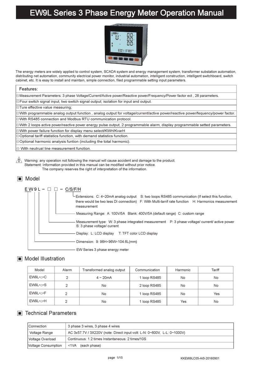
SOMMY ES925 Series User manual

Features:
⊙Measuring Items: 3 phase Voltage/Current/Active Power/Reactive Power/Frequency/Power Factor
etc, totally 28 parameters
⊙Two switch input and two switch output
⊙True effective value measurement
⊙With RS485 interface,Modbus RTU communication protocol
⊙With positive active power and reverse active power recording function, the energy consumed and
emitted can be recorded separately.
KKES925E01-A/0-20180709
3 Phase Intelligent Energy Meter User Manual
ES925 Series
!
Warning
An accident may happen and product may be damaged
if the operation does not
comply with the instruction
This series meters are widely applied to control system, SCADA system and energy management system,
transformer substation automation, distributing net automation, residence community electrical power
monitor, industrial automation, intelligent construction, intelligent switchboard, switch cabinet, etc. It is easy
to install and maintain, simple connection, programmable setting parameters on meters or computer.
1
Model
Model Indication
Dimension:
Measure Parameters: W: all the 3 phase parameters
92:96H×96W×77.5L(mm)
ES series 3 phase energy meter
Switch input or outputCommunicationAlarm or remote controlModel
ES925-W 2RS4852
Power supply consumption
Display
Power
Freqency
Current accuracy
Working environment
Alarm output
Power supply
Energy
Output digital interface
RMS measurement, accuracy class 0.5
Active / Reactive / Apparent power, accuracy 0.5 class
45~60Hz, accuracy 0.01Hz
Active Energy 1 class, Reactive Energy 2 class
LCDdisplay
AC/DC 100~240V (85~265V)
≤5VA
RS-485, MODBUS-RTU Protocol
2 switch output, 250VAC/3A or 30VDC/5A
Switch Input 2 switch input (Dry contact mode)
Temperature: -10~50℃ Humidity:<85% RH; Non-corrosive Gas; altitude ≤2500m
Current impedance
Current consumption
Voltage consumption
Voltage overload
Connection
Main Technical Parameters
Voltage range
<0.4VA (each phase)
<20mΩ
Current overload
Voltage impedance
Voltage accuracy
Current range
≥300KΩ
RMS measurement, accuracy class 0.5
AC 0.025~5A
Continuous: 1.2 times Instantaneous: 2 times/2S
3 Phase 3 Wires 3 Phase 4 Wires
AC 10-480V (L-L)
Continuous: 1.2 times Instantaneous: 2 times/10S
<1VA (each phase)
Display: L: segment LCD display
ES 92 5
□

Measurement interface switching process description:
4
An example of the power interface switching process:
Total Kwh Forward Kwh Backward Kwh Total Kvarh
Forward Kvarh Backward Kvarh
3 phase phase voltage
3 phase power factor
Total power
Frequency
3 phase current 3 phase active power 3 phase reactive powe
3 phase reactive
power
Note: 26 English letters are represented by digital tubes
English alphabet
Digital tube display
English alphabet
Digital tube display
A B CDEFGH I J K LM
N O P QR S T U VW X YZ
Measurement display interface description:
1. Under measurement status, press “ ”/ “ ”to switch display of 3 phase phase voltage, 3 phase current, 3 phase
active power, 3 phase reactive power, 3 phase appearance power, 3 phase power factor, total power, frequency etc
2. Press “ ”/ “ ” increase or decrease key to switch display of total active power, forward active power, backward active
power, total reactive power, forward reactive power, backward reactive power.
3. DO1, DO2 are used as the alarm output status indication in the alarm mode, and the switch output status indication is
made in the "remote" mode of the switch quantity.
4. COM flashing means communicate is acting.
5. P(Kwh) means Total Active Energy (algebraic sum of forward active energy and backward active energy); Q(Kvarh)
means Total Reactive Energy (algebraic sum of forward reactive energy and backward reactive energy).
5
Menu Modification Illustration
Menu Structure and Function Description
Alarm mode
Alarm value
Alarm hysteresis
value
Alarm value unit
Alarm action
delay
Alarm end time
The second way alarm related parameter setting method refers to the first way
When value is DO, it is remote control mode, otherwise
it is alarm mode, please refer to Table 1 as below
1st alarm value setting (unit is standard display unit)
Alarm action delay time, unit: second
Alarm action reset time, unit: second
Alarm Setting
/ /
1st level
2nd level
3rd level Description
When input 1111, user can clear energy ; When
input 1234, the menu can be reset to default setting
Modify password, factory default setting 0000, no
password
Backlight lighting delay time, unit “second”. When value
is “0” , it will keep on lighting all the time
Software version, read only
System Setting
Clear Energy
Signal Setting
Set power net input mode, 3 phase 3 wire or 3 phase
4 wire
Primary voltage, unit KV
Network
Voltage transform
Current transform
Voltage transform
Current transform
Communication
Setting
Meter address range
Baud Rate 1k2 means 1200, 2k4 means 2400,
4k8 means 4800 9k6 means 9600
High register is in front or low register is in front
Address
Baud rate
Data sequence
User Password
Backlight time
Software Version
The page turning time is measured in seconds. No page
turning when the value is "0"
Page Turning
Time
/
/
/
/
/ /
Parity Bit No parity/even parity/odd parity
/ /
Alarm relay
selection /
The value is“SECD”:display 2times measurement
The value is “PRI”: display 1 time measurement
Primary and secondary
selection
1: means international standard unit, K: 1000 times of
international standard unit, M: 1000000 times of
international standard unit
1st alarm hysteresis value setting ( unit is standard
display unit)
1st alarm replay output selection
Secondary voltage, unit KV
Primary current, unit A
Secondary current, unit A
Under User Menu Status
1
.
Press SET Key more than 5 seconds, if setting password, it will pop up a dialog box, input the correct password to enter
into user menu, to modify parameter.
2
.
If the present display is 1st level
,
press SET
Key enter into next level
display
,
press
“ ” “ ”
key to change menu subitems.
3
.
If the present display is 2nd or 3rd level, press ESC Key, return to previous display.
4
.
If present display is 3rd level, press “ ”, “ ” to flash the digit, press“ ”, “ ” to move position , press“ ”, “ ” Key to
modify value; press SET Key to save setting value when flashing; if press ESC Key, setting value will not be saved and
return to the 2nd level display.
5
.
After modifying the parameters, press SET Key more than 5 seconds or press ESC Key to exit user menu and enter into
measuring status.

2
Dimension
Connection Drawing
The correct diagram on the Meter shall prevail
A+ B-
R S 4 8 5 D I 1 D I 2
SCOM S2S1 COM1 AL1 N L
AC / DC
100~240V
Ic
13
Ua
(Ua)
UbUc
(Uc)
Un
(Ub)
Ia*Ia
Ib*IbIc*
112 11 10 9 8 7 6 5 4 3 2
AL1
COM2 AL2
AL2
COM
1415161819202122 17
POWER
Panel Size Mounting Size
96
96
92.0 +0.5
-0 25
Storage environment -40~70℃
Withstand voltage
Weight
Isolation
Dimension 96H×96W×61.5L(mm)
Power supply and 485 interface, DI interface≥DC 2000V
Input/ Output/ Power supply to meter cover>5MΩ
0.5kg
Side-face Siz
77.5
6.5
96
84.5
Note: Voltage input connection terminal, labels in bracket show 3 phase 3 wire connection method; if there is any
change, please turn to the correct diagram on the Meter
Panel Indication
Return Key
Left Key
Right Key
Set Key
Increase Key
Decrease Key
Item FunctionNameSymbol
1
2
3
4
5
6
△For backspace in menu operation
△
Shift menu and move data postion in menu operation
△
Shift menu and move data postion in menu operation
△Press this key for 5s to enter the menu
△Enter data modification in menu operation
△Enter data modification in menu operation
3
△To confirm the modified menu value
△
To shift measure interface outside of the menu
△
To shift measure interface outside of the menu
△To shift energy page outside of the menu
△To shift energy page outside of the menu
△Back to previous menu
2
3
1
4
5
6
16
14 15
13
A
B
C
N
Mode 1 (3 pcs CT): 3 phase 4 wire connection mode
A
B
C
N
17 18 19 21 22
20 16
14 1513
Voltage inputCurrent Input
Mode 2 (2 pcs CT): 3 phase 3 wire connection mode
16
14 1513
A
B
C
Voltage input
A
B
C
17 18 19 21 2220 16
14 1513
* *
Current Input
Voltage direct input Voltage input via PT
Voltage direct input Voltage input via PT
Current input via CT
Current input via CT
3
4
DO1
DO2
DO3
P
DO4
v
v
v
B
A
C
COM1
SET
ESC
Explanation:
A.Voltage input
:
I
nput voltage should not be higher than the rated input voltage of meter
,
o
therwise a PT should be used.
B.Current input
:
Standard rated input current is 5A. ACT should be used when the input current is bigger than 5A.
If some other meters are connected with the same CT, the connection should be serial for all meters.
C.Please make sure that the input voltage is corresponding to the input current, they should have the same phase
sequence and direction,otherwise data and sign error may occur (power and energy).
D.The connection mode of meter which is connected to power network should depend on the CT quantity. For 2pcs of
CT,it should be 3 phase 3 wire connection. For 3 pcs of CT,it should be 3 phase 4 wire connection.
Meter wire connection, the input network Link setting in the software menu should accord to the connection mode of
the measured load.Otherwise, the measured voltage or power is incorrect.
E. Please pay high attention on the difference between 3 phase 3 wire and 3 phase 4 wire connection. Becasue wrong
connection may lead to incorrect calculation of power factor, power and energy.
Caution:
1.Power supply connection must be correct.
2.Pay attention on the phase sequence of voltage signal input.
3.Current signal input should be connected as per the connection drawing.
4.Connection mode should accord to the setting of user menu “LIN”.
5. Isolation between power supply and circuid board, in cause of leakage switch wrong action

6
Note :Menu modification example
Eg1: Method of setting current ratio
Eg 2: Method of setting communication address
Meter Address
Setting
Communication
Setting
SETSET
Flash
Primary current
setting
( Unit: A)
Secondary current
setting
(Unit: A)
SET
SET
Flash
Flash
Level 1
Level 2
Level 3 Modified state
Modified state
Measuring
Status System Setting
Signal Setting
SET
more than
5 seconds
SET
/
/
Level 1
Level 2 Level 3
Measuring
Status System Setting
Signal Setting
SET
more than
5 seconds
/
/
/
/
/
/
/
7
UL(AB/BC/CA line voltage)
Ubc(BC line voltage)
Uca(CA line voltage)
Ia(A line current)
Ib(B line current)
14
12
16
18
20
13
11
15
17
19
(UbcL)
(UcaL)
(ULL)
(IaL)
(IbL)
(UbcH)
(UcaH)
(ULH)
(IaH)
(IbH)
6
7
8
9
10
(IcL)
(IL)
(PaL)
(PbL)
(PcL)
(PL)
(QaL)
(QbL)
(QcL)
(QL)
(SaL)
(SbL)
(ScL)
(SL)
(PFaL)
(PFbL)
(PFcL)
(IcH)
(IH)
(PaH)
(PbH)
(PcH)
(PH)
(QaH)
(QbH)
(QcH)
(QH)
(SaH)
(SbH)
(ScH)
(SH)
(PFaH)
(PFbH)
(PFcH)
Qb(B phase apparent power)
Qc(C phase apparent power)
Q(total reactive power)
Sa(A phase apparent power)
Sb(B phase apparent power)
Sc(C phase apparent power)
S(total apparent power)
PFa(Aphase power factor)
5327 54
26
PFb(B phase power factor)
PFc(C phase power factor)
51 52
18
19
20
21
22
23
24
25
36
38
40
42
44
46
48
50
35
37
39
41
43
45
47
49
I(A/B/C line current)
Ic(C line current)
Pa(A phase active power)
Pb(B phase active power)
Pc(Cphase active power)
P(total active power))
Qa(A phase apparent power)
11
12
13
14
15
16
17
22
24
26
28
30
32
34
21
23
25
27
29
31
33
(PFLL)
(FL)
(EPL)
(EQL)
(PFLH)
(FH)
(EPH)
(EQH)
EP(Total active energy)
EQ(Total reactive energy)
5528
29
30
31
57
59
61
56
58
60
62
(UNNB)
(INNB)
(ULNB)
(PNNB)
Unbalanced difference
Unbalanced difference
32
33
63
65
64
66
PF(Total power factor)
F frequency
No. Item ON/OFF output (low alarm) code ON/OFF output (high alarm) code
Ua(A phase voltage)
Ub(B phase voltage)
Uc(C phase voltage)
U(A/B/C phase voltage)
Uab(AB line voltage)
1
3
5
7
9
(UaL)
(UbL)
(UcL)
(UL)
(UabL)
(UaH)
(UbH)
(UcH)
(UH)
(UabH)
1
2
2
3
4
4
5
6
8
10
Reference table: for alarm output electric parameters
1. DO1 and DO2 functions can be used for “remote control” electrical equipment; when using this function, the
alarm mode should be selected as 0(DO), otherwise DO1, DO2 act as alarm AL1, AL2 output; DO1, DO2
remote control is through RS485.
2. Communication(plese refer to communication protocol manual)
3. The alarm function, after power on, the meter runs stably for more than 5S, then alarm starts to operate. (The
corresponding relationship of alarm settings is shown as the below stable)
In 3 phase 4 wire code , the corresponding communication alarm code is as following:
UCAL=13,UCAH=14,UBCL=11,UBCH=12
This manual suits for next models
1
Table of contents
Other SOMMY Measuring Instrument manuals
Popular Measuring Instrument manuals by other brands
Thermo Scientific
Thermo Scientific 43iQTL instruction manual
Tektronix
Tektronix Keithley 2601B-PULSE quick start guide
CellScale
CellScale MSI9850 user guide
DAKOTA ULTRASONICS
DAKOTA ULTRASONICS MX-3 Operation manual

Hydro Instruments
Hydro Instruments VM-150 instruction manual

Partlow
Partlow MRC 7800 Installation, Wiring, Operation Manual
