CLINTON INDUSTRIES 189 User manual

ML189-3A
CLINTON'S
MODEL 189
UNDERBED TRIMMER
FOR
SINGER 591
SERVICE
MANUAL
40-0152-01

ML1889-25B
TABLE OF CONTENTS
THREAD TRIMMER SECTION
SECTION I - GENERAL INFORMATION . . . . . . . . . . . . . . . . . . . . . . . . . . . . . 1
A.
B.
C.
INTRODUCTION . . . . . . . . . . . . . . . . . . . . . . . . . . . . . . .
APPLICATION . . . . . . . . . . . . . . . . . . . . . . . . . . . . . . . . . . .
TRIMMER COMPONENTS . . . . . . . . . . . . . . . . . . . . . . . .
1
1
1
SECTION II - INSTALLATION . . . . . . . . . . . . . . . . . . . . . . . . . . . . . . . . . . . . . 2
SECTION III - AIR CIRCUIT OPERATION . . . . . . . . . . . . . . . . . . . . . . . . . . . . . 2
A.
B.
C.
NEEDLE COOLER . . . . . . . . . . . . . . . . . . . . . . . . . . . . . .
TRIM VALVE AND PILOT VALVE . . . . . . . . . . . . . . . . . . .
FOOTLIFT, FOLDER OPENER & THREAD BLOWER . .
2
2
3
SECTION IV - ADJUSTMENTS . . . . . . . . . . . . . . . . . . . . . . . . . . . . . . . . . . . . . . 3
A.
B.
C.
D.
TRIMMER . . . . . . . . . . . . . . . . . . . . . . . . . . . . . . . . . . . . . .
THREAD PULLOFF CYCLE TIME . . . . . . . . . . . . . . . . . .
TRIM CYLINDER SPEED . . . . . . . . . . . . . . . . . . . . . . . . .
NEEDLE THREAD BLOWER BLAST TIME . . . . . . . . .
3
4
4
4
SECTION V - TROUBLE SHOOTING . . . . . . . . . . . . . . . . . . . . . . . . . . . . . . . . 5
SECTION VI - PARTS DRAWINGS . . . . . . . . . . . . . . . . . . . . . . . . . . . . . . . . . . 6-18

ML1889-26
I. GENERAL INFORMATION
A. INTRODUCTION
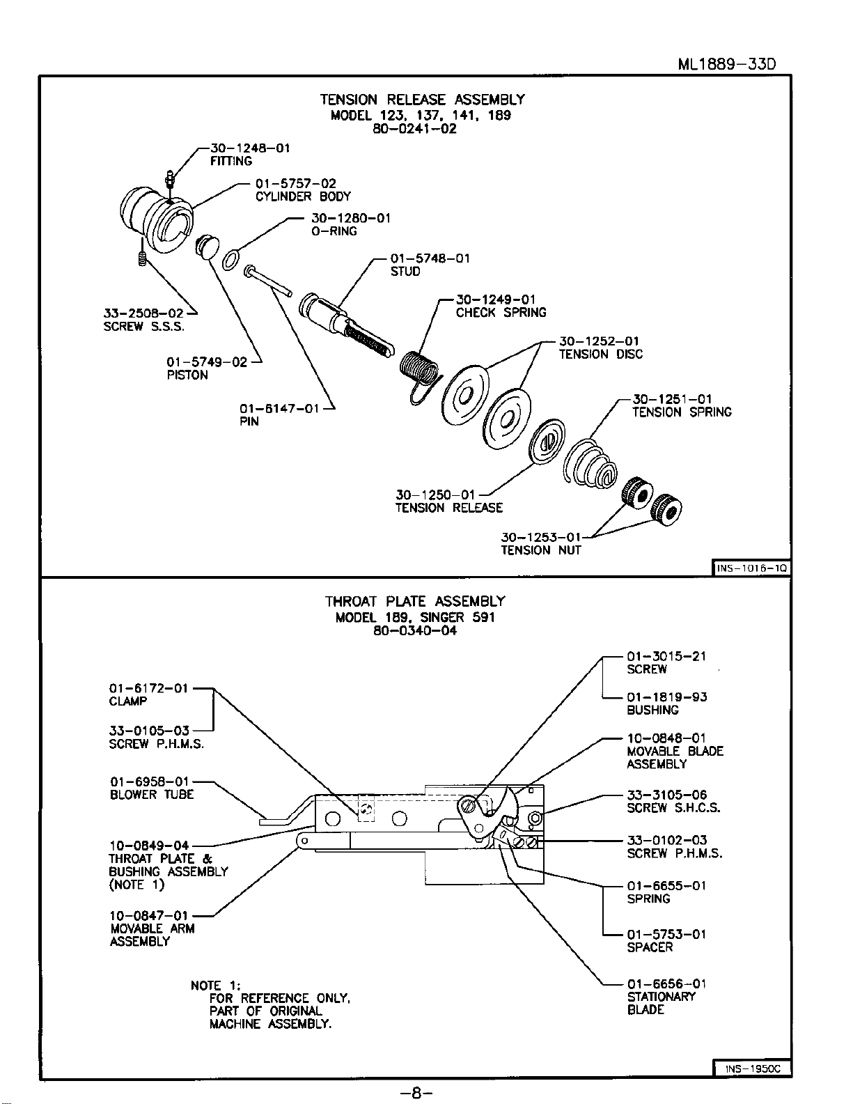
The air Operated Underbed Trimmer contains a trimming system that cuts both the
needle and bobbin threads simultaneously. A movable and a stationary blade, mounted
on the throat plate are used in combination to pick up and cut the threads.
Solid state electronics are used to sense the position of the needle and to trigger the
trimming mechanism at the proper time as well as to control footlifting and backtacking
operations.
B. APPLICATION
The underbed Trimmer/Positioner enables the operator to automatically control the
position of the needle in or out of the work, thereby eliminating the need for hand position-
ing. In addition, the top and bottom threads are automatically cut beneath the throat
plate after positioning. This eliminates the need for hand trimming.
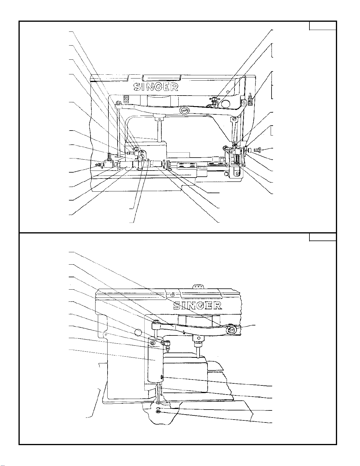
C. TRIMMER COMPONENTS
The trimmer components, which can be either pre-installed on the sewing machine head
and factory tested, or field installed, include:
1. Standard Components
a. Thread Cutter Assembly
b. TensionReleaseAssembly
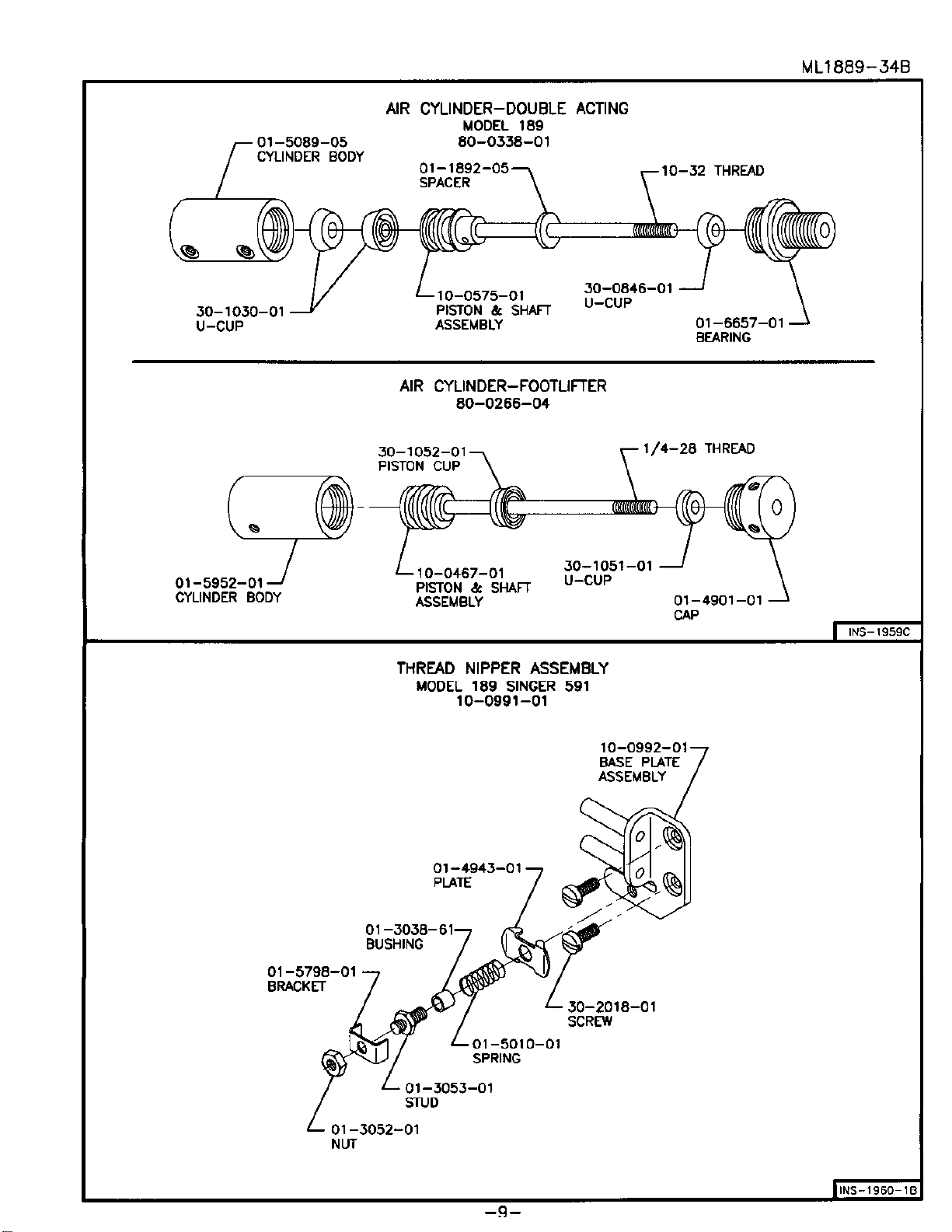
c. Needle Thread Pulloff Assembly
d. Needle Thread Blower and Needle Cooler Assembly
e. Foot Lifter
f. FolderOpener
g. Solenoid Air Valve Control Unit
- 1 -

ML1889-27
II. INSTALLATION
A. Install the solenoid air valve assembly under the table as shown in drawing INS-1954.
B. The treadle air valve is used in place of the treadle rods for the needle cooler. Refer to
speed control installation on page 7.
C. The folder opener air valve is installed as shown in (INS-1955). This should be placed in
a position convenient to the operators right knee.
D. Set the machine head in the table and install the "V" belt.
E. Connect all electrical cables tot he control box.
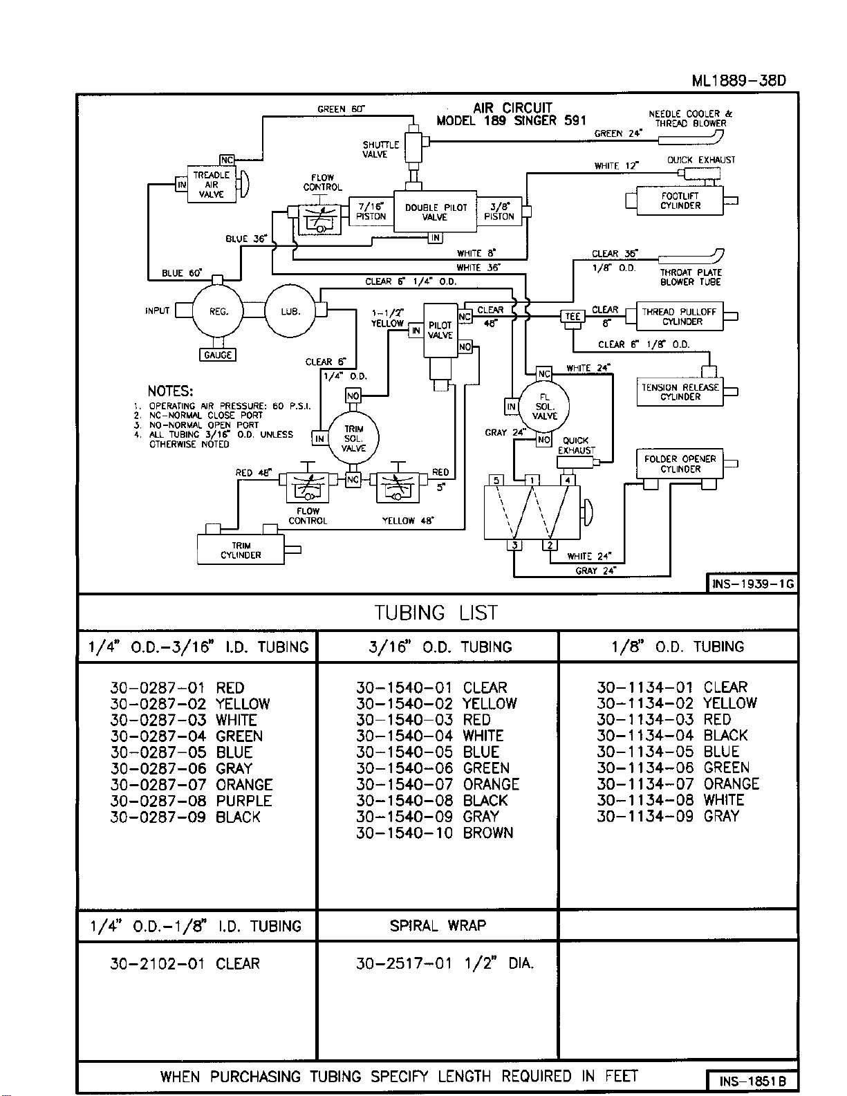
F. Connect all air lines as shown in circuit diagram drawing INS-1939-1.
Note: Do not connect the air supply at this time.
G. Thread the machine and sew on material being used for the operation.
H. When heeling the treadle observe the 6 o'clock positioning of the thread across the hook.
If it is not between 5 and 6 o'clock readjust as described under synchronizer timing page
11.
I. Connect the air supply then sew and operate the trimmer. Refer to section III for air
circuit operations and section IV for adjustments.
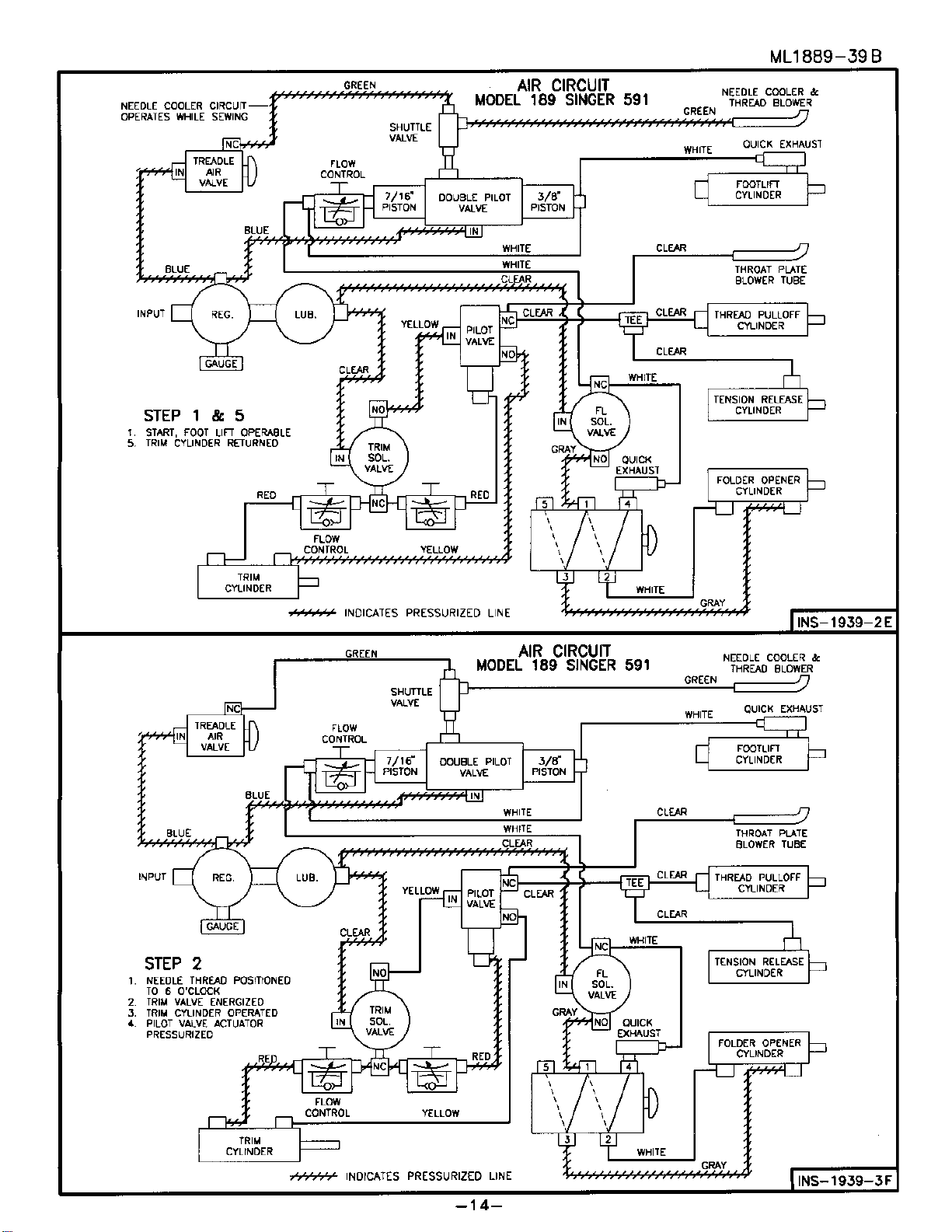
III. AIR CIRCUIT OPERATION
A. NEEDLE COOLER
Air is distributed throughout the circuit as shown in INS-1939-2. When the treadle is
pushed forward for sewing the treadle valve is opened and air flows to the needle cooler
tube.
B. TRIM VALVE AND PILOT VALVE
At the end of the sewing operation the brake is applied and the needle positioner is
activated. The needle positioner will stop with the needle thread across the hook in the 6
o'clock position. The trim solenoid valve will energize. (See INS-1939-3). The trim
cylinder operates. The pilot valve actuator is pressurized shifting the pilot valve. There is
no air flow through the pilot valve since there is no pressure at the input.
- 2 -

ML1889-28
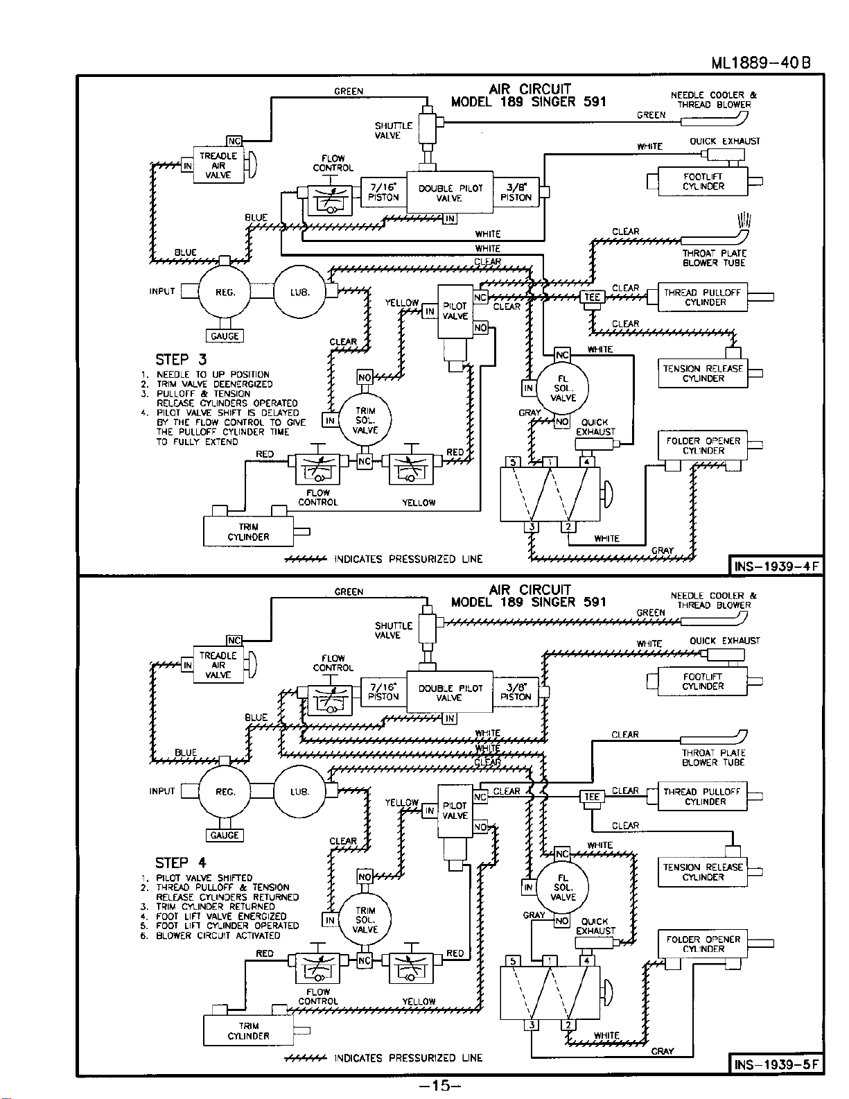
The needle is raised to the up position and the trim valve is deenergized.
(See INS-1933-4). The flow control in the pilot valve actuator circuit leaks the air slowly
from the actuator keeping the valve shifted. Air is applied to the IN port through the NC
port, now open, to the thread pulloff cylinder, tension release cylinder and throat plate
blower tube.
The pilot valve returns (INS-1939-5). Air is applied to the trim cylinder to return the
blade. The rate or speed of return is controlled by the flow control which controls the air
exhausting from the trim cylinder. This control is used to minimize bobbin spin.
C. FOOTLIFT, FOLDER OPENER andTHREAD BLOWER
While the treadle brake is still applied the foot lift solenoid valve will energize
(see INS-1939-5). Air is applied to the foot lift cylinder and the folder opener. The folder
can be operated independent of the footlifter at any time in the cycle with a knee oper
ated air valve.
At the same time air is applied to the double pilot valve actuators. One actuator has a
larger piston than the other. The larger piston will have more force than the smaller one
at the same pressure. The air flow to the larger piston is restricted by the flow to the
larger piston is restricted by the flow control When air is first applied the smaller piston
will shift the valve and open the port to the shuttle valve. Air will flow to the needle
thread blower. Pressure is slowly increasing in the larger piston until it overcomes the
other and shuts off the air supply to the blower.
IV. ADJUSTMENTS
A. TRIMMER
1. Cutter Assembly
In the cut position the cutting edge of the movable blade should pass the cutting
edge of the stationary blade about 1/16". If adjustment is required loosen the lock
nuts on the cylinder shaft and adjust as required.
The pickup position on the movable blade is controlled by the stroke length of the
cylinder and proper positioning of the cutting edge as above.
2. Thread Pulloff and Tension Release
No adjustment is required for the Thread Pulloff and Tension Release assemblies for
trimmer operations. If check spring adjustment is required for stitch formation,
remove the assembly from the machine, loosen the stud lockscrew, adjust spring
tension, tighten lockscrew and replace assembly.
- 3 -

ML1889-29
B. THREAD PULLOFF CYCLE TIME
The flow control in this circuit determines the time these cylinders have to complete
their stroke. Too much time will show a noticeable hesitation before return of the pulloff
cylinder. If the time is short the cylinder will not complete its stroke. Turning is (cw) will
increase time, turning out (ccw) will decrease time.
C. TRIM CYLINDER SPEED
Turning the flow control needle in (cw) will slow down the cylinder and reduce spin.
Turning out (ccw) will increase cylinder speed. If cylinder speed is too slow the presser
foot will rise before the thread is cut and the operator could start removing the garment
too soon. If this happens the cylinder speed should be increased and some mechanical
device such as star springs used in conjunction with the flow control to reduce spin.
D. NEEDLE THREAD BLOWER BLAST TIME
The duration of this blast is controlled by the flow control mounted to the larger actuator.
Turning in (cw) increases time turning out (ccw) decreases time. About one second is
enough to give the operator time to remove the garment and blow the thread above the
foot. Should the operator be delayed in removing the garment the thread will remain
under the foot. If the foot is lowered and again raised the above sequence will repeat.
- 4 -

- 5 -
PROBLEM CAUSES CORRECTIVE ACTION
Needle thread not cut.
Bobbin thread is cut
Defective PC Board Replace board
Movable blade missed
needle loop Check synchronizer timing
to see that trimmer is fired
at correct time
Binds in trimmer linkage Locate and remove bind. A
light bind would slow it
enough to miss needle loop
Both threads not cut not
picked up
Defective movable blade Replace
Water in air lines Check filter. Remove water
from air lines
Defective solenoid air valve
or air cylinder Repair or replace
Defective PC board Replace board
Binds in trimmer linkage Locate and remove bind
Both threads picked up, not
cut
Defective movable or
stationary blade Replace
Stroke misadjusted failing
to reach cutting position Readjust
Needle thread cut short Pulloff cylinder improperly
adjusted Readjust
Long tail left on top side at
start of sewing Blower not operating
causing thread to be
trapped under presser foot.
Operator not removing
garment fast enough
Check blower circuit qand
flow control adjustment. If
blower time is short
readjust flow control to
increase
Bobbin thread is cut short
Bobbin tension too tight Loosen bobbin tension as
much as possible
Bobbin thread slipped out of
hook on case Run Bobbin thread through
hook
Bobbin case without hook
being used Replace with correct bobbin
case
ML1889-30A
V. TROUBLE SHOOTING

ML1889-31C
INS-1940E
INS-1944F
FOLDER ASSEMBLY
MODEL 189
SINGER 591
80-0384-01
01-3066-01
SCREW
01-3286-01
BUSHING
FOLDER ASS'Y
SEE NOTE
30-1936-01
AIR CYLINDER
33-1508-01
HEXNUT
33-0706-24
SCREW-FIL.H.M.S.
33-1806-01
INTERNAL TOOTH WASHER
30-1783-01
ELBOW
01-6939-01
FACE PLATE
10-0991-01
THREAD NIPPER
ASSEMBLY
30-1729-01
AIR FITTING
80-0338-01
AIR CYLINDER
01-3061-11
SCREWF.H.M.S.
01-6947-01
BRACKET
33-1628-02
HEXNUT
THREAD PULLOFF AND CUTTER DRIVE ASSEMBLY
MODEL 189
SINGER 591
80-0382 -01
80-0383-01
01-6940-01
BLOCK
33-3105-05
SCREWS.H.C.S.
33-1805-01
LOCKWASHER
30-0463-01
RETAINING
RING
01-3800-01
PIN
01-6941-01
ROD
30-1164-01
NUT
01-6942-01
BLOCK
01-6944-01
NUT
30-0813-01
O-RING
01-6945-01
ESNA NUT
30-0920-01
AIRCYLINDER
30-1729-01
AIRFITTING
01-6943-01
ROD
30-0618-01
NUT
01-4907-01
LINK
NOTE: ALL PARTS NOT IDENTIFIED ARE SUPPLIED BY SINGER. SEE SINGER PARTS MANUAL.
33-1710-01
FLAT WASHER
33-1506-01
HEXNUT
ML1889-32D
30-1124-01
PLUG
01-6953-01
BRACKET
30-0139-01
CLAMP
30-1800-01
TEE
30-1258-01
PILOTACTUATOR
33-0105-04
SCREW-
P.H.M.S.
EXISTING
SCREW
30-1783-01
ELBOW
30-1615-01
VALVE
30-1648-01
COUPLING
30-1729-01
TUBEFITTING
30-1749-01
COUPLING
30-0819-01
FLOWCONTROL
30-1896-01
TEE
30-1104-01
REDUCER
30-1754-01
PILOTACTUATOR
30-1935-01
VALVE
FOOTLIFTER ASSEMBLY - MANIFOLD ASSEMBLY
MODEL189
80-0180-87
SINGER 591V
33-2210-03
SCREW-S.S.S.
01-6818-01
ROD
545873- SWIVEL SINGER PART
(SEENOTE)
30-0618-01
ELASTICSTOPNUT
NOTE:
REMOVETHECONNECTING ROD SWIVEL
FROMTHELIFTER ARM ANDTRANSFER IT
TOTHELOWER BELL CRANK. RETAIN THE
SWIVEL WITH 30-0618-01 ELASTIC STOP
NUT.
REMOVESPACER FROM UNDERTHE HEAD
OFTHE PIVOTSTUD AND PLACE IT
BETWEENTHE LIFTER ARMAND THE
MACHINE. THIS WILL SPACE THE ARM 1/8"
FURTHERFROMTHEMACHINE. IF
ADDITIONALCLEARANCE IS NECESSARY,
USE01-4379-01 SPACER AS REQUIRED.
C'BORELIFTERARM EQUALTOTHE
SPACERS USED. EACH SPACER IS
.082 THICK.
PIVOTSTUD
LIFTERARM
33-1616-02
JAMHEX NUT
01-6817-01
NUT
30-1104-01
REDUCER
30-1615-01
QUICKEXHAUST
30-1299-01
PIPEPLUG
30-1729-01
FITTING
80-0266-04
AIRCYLINDER
NEEDLE THREAD BLOWER AND PRESSER FOOT ROLLER ASSEMBLY
MODEL189
80-0386-01
80-0413-01
SINGER 591
30-2125-01
BULKHEADTEE
01-6971-01
BRACKET
33-0106-04
SCREW-P.H.M.S.
30-1940-01
TIEANCHOR
30-1382-01
CABLETIE
33-0106-03
SCREW-P.H.M.S.
01-6956-01
SHANK
01-6955-01
TUBE
30-2024-01
TUBELOCK SCREW
30-1559-02
SCREW
01-1829-21
BUSHING
01-6954-01
BLOCK
01-7557-01
DRIVEROLLER
01-2221-02
SPACER
INS-1953C
INS-2016D


SPIRAL WRAP INSTALLATION
MODEL 189
UNION SPECIAL 63900
ML1889-58B
30-2517-01
SPIRAL WRAP
(1/2" DIA.)


ML-000-5B
30-1160-01
BONNET
30-1108-01
FILTER ELEMENT
5 MICRON 30-1561-01
BOWL
30-1085-01
BOWL
30-1610-01
LUBRICATOR
REPAIR KIT
(CONTAINS ITEMS
18,20,22)
30-2788-01
FILTER/REG.
REPAIR KIT
(CONTAINS ITEMS
3,4,5,6,7,8,10,14,16)
INS-2100-2A INS-2100-1B
FILTER, REGULATOR, AND LUBRICATOR
30-2347-01
FILTER/REGULATOR
OPERATION
AIRENTERS THE INTEGRALFILTER/REGULATORUNITAND IS DIRECTEDDOWNWARD
THROUGH A SET OF LOUVERS (10) TOIMPART A WHIRLING ACTION. THIS CENTRI-
FUGALACTION CAUSES LIQUIDPARTICLESTOBE SEPARATED FROMTHE AIRSTREAM
ANDSETTLE TOTHE BOTTOM OF THEBOWL. ACCUMULATEDLIQUID ISDRAINED
MANUALLY (15).
AIRTHENPASSES THROUGHTHE SINTEREDBRONZEFILTERELEMENT (11)WHERE
SMALLERSIZE FOREIGN PARTICLES AREREMOVED.
THECLEAN AIR PASSES THROUGHTHE VALVE (5,6,7,8) OF THE REGULATOR AND IS
CONTROLLEDTOAPRESSURE,DETERMINED BY THEADJUSTMENTOF THE REGULATOR.
PRESSUREIS INCREASEDBY ROTATINGTHE KNOB CLOCKWISE, OR DECREASED BY
ROTATINGTHEKNOBCOUNTERCLOCKWISE.
CAUTION: THIS MINIATURE INTEGRAL FILTER/REGULATOR SHOULD NOT BE USED IN
APPLICATIONS WHICH MAY EXCEED 250 PSIG. DURING MAINTENANCE PERIODS,
INSPECT AND CLEAN EACH PART CAREFULLY, USING ONLY CLEAR, WARM
WATER OR KEROSENE. DO NOT USE SOLVENTS AS THE POLYCARBONATE BOWL
MAY BE DAMAGED.
MAINTENANCE:
REGULATORSECTION: DISASSEMBLETHE REGULATORSECTIONAS FOLLOWS: TURNOFF
AIRSUPPLY. TURNTHEADJUSTING KNOB COUNTERCLOCKWISETORELIEVE COMPRESSION
ONTHEREGULATINGSPRING (2). UNSCREWTHE BONNET (1),REMOVE THE REGULATING
SPRING (2), AND PISTON ASSEMBLY (4). UNSCREW THE VALVE SEAT (5) WITH A 3/8"
SOCKETAND REMOVE THE VALVEASSEMBLY (7) AND VALVE SPRING (8).
CLEANAND INSPECT EACH PART FOR WEAR ORDAMAGE. REPLACE IF NECESSARY.
CAUTION: WHEN REASSEMBLING, VALVE SEAT (5) SHOULD NOT BE TIGHTENED TO MORE
THAN 4 TO 6 INCH POUND TORQUE. BONNET ASSEMBLY (1) SHOULD BE
TIGHTENED 50 TO 60 INCH POUNDS TORQUE.
MANUALDRAIN FILTERSECTION: TOSERVICETHE FILTER SECTIONSHUT OFTHE AIR
PRESSURE. UNSCREWBOWL ASSEMBLY (14) ANDREMOVE "O" RING (9) UNSCREW STUD (13)
ANDFROM THESTUD REMOVEFILTERELEMENT (11),LOUVER (10)AND GASKETS (12).
THEFILTERELEMENT SHOULD BE CLEANED PERIODICALLY WITH KEROSENE AND BLOWN
OUTWITH COMPRESSED AIR.
AFTERCLEANING, INSPECTEACH PARTCAREFULLY,REPLACE ANYDAMAGED PARTS. WHEN
REASSEMBLING,TIGHTENSTUD (13)TO5 TO 10 INCHPOUNDS TORQUE.
LUBRICATOR
CAUTION: THIS UNIT HAS A POLYCARBONATE BOWL.
1. BESURE ITIS NOTMOUNTED WHERETEMPERATURESOF 125 FOR MORE WILL BE
NEARIT, OR ON A LINE WHERE AIRPRESSURE EXCEEDS 150PSI.
2. BEWAREOF CONDITIONS,FUMES AND FLUIDSTHAT WILLHARM THETRANSPARENT
BOWL.
3. TOCLEAN BOWL, RINSE OR WIPE WITH APETROLEUM SOLVENT ONLY,SUCHAS
KEROSENE,ORHOUSEHOLDDISHWASHERDETERGENT.
4. DO NOT USENEAR, ORCLEAN WITHSUCH MATERIALSAS ACETONE,ALCOHOL,
BENZENE,DIOXANE,ETHEL ACETATE, LACQUERTHINNER, TOLUENE,CHLORIDE,
CARBONTETRACHLORIDE, ALKALIES, AMINES,ESTERS, KETONESAND AROMATIC
HYDROCARBONS.
5. DO NOT INSTALL ON A COMPRESSED AIR LINE WHERE THECOMPRESSOR ISLUBRI-
CATED WITH,OR THE AIR CONTAINS,A SYNTHETIC,FIRE-RESISTANT LUBRICANT.
IMPORTANT: INSTALLATIONS INSTRUCTIONS FOR LUBRICATORS.
WHERE AND HOW TO INSTALL:
1. INSTALL AS CLOSE AS FEASIBLE TOEQUIPMENT TOBE LUBRICATEDWITH AIR
FLOWINGIN AND OUT PORTS SOMARKED.
2. TOFILLTHE LUBRICATOR,TURNOFF AIR PRESSURE, REMOVE BOWL AND FILL.
3. POURIN ONLYCLEAN OIL. SAE10 OR LIGHTER USUALLY IS BEST, NEVER USE
ONEOF THEFOLLOWING OILS: CELLULUBE #150 AND #220, KANO KROIL,
KEYSTONEPENETRATINGOIL #2 ORPYDRAUL AC.
4. AS SOON AS AIR PRESSURE REBUILDSINSIDE THEBOWL, OIL WILL DRIP THROUGH
THESIGHT GAUGE. CONTROL THERATEOF OIL ENTERINGTHE AIR STREAMBY
TURNINGTHE ADJUSTMENT SCREW DOWN TOGIVE LESS OIL AND UPTO GIVE MORE
OIL. THISIS AUNIQUE LUBRICATOR. YOUADJUSTTHIS TYPE SO THAT WHILE
THESMALLEST AMOUNT OFAIR IS FLOWINGTHROUGH IT YOUGET THEDESIRED
AMOUNTOF OIL FOR THATFLOW. THEMORETHE AIRFLOW INCREASES,THE MORE
OILYOU WILLNEED AND THE MORE YOU WILL GET AUTOMATICALLY.
HOWTOMAINTAIN:
1. PERIODICALLY CLEAN ADJUSTING SCREW NEEDLE VALVE AND SEAT BY SWISHING A
CLEANERAND BLOWING OFF WITH AIR.
2. DRAIN OFF ANYCONTAMINANTSOR WATERIF THEY SETTLEIN THEBOTTOM OF
THEBOWL.
30-2797-01
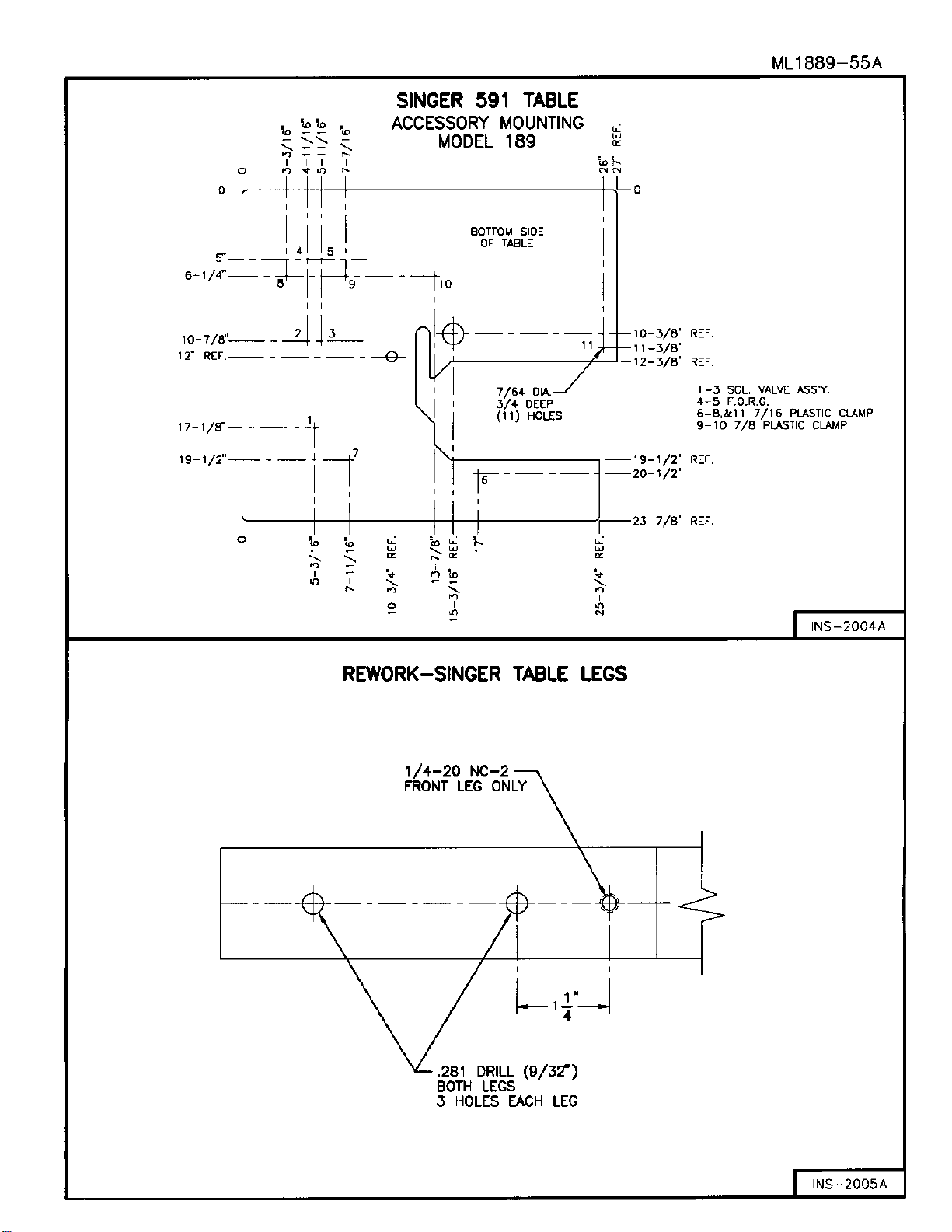
Table of contents
Other CLINTON INDUSTRIES Trimmer manuals


