CLINTON INDUSTRIES 199 User manual
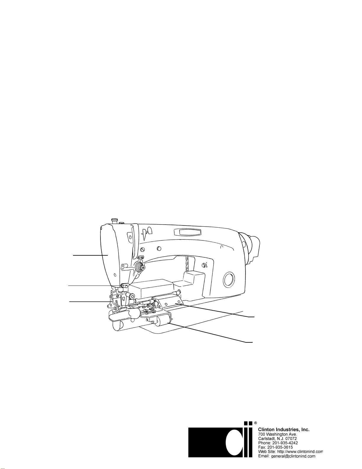
TRIM AND WIPER
ASSEMBLY
FOLDER OPENER
PULLOFF
ASSEMBLY
NIPPER
NEEDLE
COOLER
40-0252-01
SERVICE MANUAL
ML199-4
CLINTON'S
MODEL 199
UNDERBED TRIMMER
FOR
UNION SPECIAL 63900

ML199-5
TABLE OF CONTENTS
THREAD TRIMMER SECTION
SECTION I GENERAL INFORMATION . . . . . . . . . . . . . . . . . . . . . . 1
A. INTRODUCTION . . . . . . . . . . . . . . . . . . . . . . . . . . . 1
B. APPLICATION . . . . . . . . . . . . . . . . . . . . . . . . . . . . . 1
C. TRIMMER COMPONENTS . . . . . . . . . . . . . . . . . . . 1
SECTION II TRIMMER INSTALLATION . . . . . . . . . . . . . . . . . . . . . . 2
A. PULLOFF ASSEMBLY . . . . . . . . . . . . . . . . . . . . . . . 2
B. TENSION RELEASE AND PULLOFF ASSEMBLY. . 2
C. CUTTER AND WIPER ASSEMBLY . . . . . . . . . . . . . 2
D. SOLENOID AIR VALVE CONTROL UNIT. . . . . . . . . 2
E. NEEDLE COOLER . . . . . . . . . . . . . . . . . . . . . . . . . 2
F. FOLDER OPENER . . . . . . . . . . . . . . . . . . . . . . . . . . 2
SECTION III PRELIMINARY SETTINGS . . . . . . . . . . . . . . . . . . . . . . . 3
SECTION IV TRIMMER ADJUSTMENTS . . . . . . . . . . . . . . . . . . . . . . 3
A. TENSION RELEASE AND PULLOFF ASSEMBLY . . 3
B. CUTTER AND WIPER ASSEMBLY . . . . . . . . . . . . . 3
C. SOLENOID AIR VALVE CONTROL UNIT . . . . . . . . 3
D. FOOTLIFTER ASSEMBLY . . . . . . . . . . . . . . . . . . . 3
E. NEEDLE COOLER . . . . . . . . . . . . . . . . . . . . . . . . . 4
F. FOLDER THREAD WIPER . . . . . . . . . . . . . . . . . . . 4
SECTION V TRIMMER SEQUENCE OF OPERATION . . . . . . . . . . . 4
A. UNDERBED TRIMMER . . . . . . . . . . . . . . . . . . . . . . 4
B. TENSION RELEASE . . . . . . . . . . . . . . . . . . . . . . . . 4
C. NEEDLE THREAD WIPER . . . . . . . . . . . . . . . . . . . 4
SECTION VI TROUBLE SHOOTING . . . . . . . . . . . . . . . . . . . . . . . . . 5
SECTION VII PARTS DRAWINGS . . . . . . . . . . . . . . . . . . . . . . . . . . . . 6-12

ML199-6
I. GENERAL INFORMATION
A. INTRODUCTION
The air Operated Underbed Trimmer contains a trimming system that cuts both the
needle and bobbin threads simultaneously. A movable and a stationary blade, mounted
on the throat plate are used in combination to pick up and cut the threads.
Solid state electronics are used to sense the position of the needle and to trigger the
trimming mechanism at the proper time as well as to control footlifting and backtacking
operations.
B. APPLICATION
The underbed Trimmer/Positioner enables the operator to automatically control the
position of the needle in or out of the work, thereby eliminating the need for hand position-
ing. In addition, the top and bottom threads are automatically cut beneath the throat
plate after positioning. This eliminates the need for hand trimming.
C. SYSTEM COMPONENTS
The trimmer components, which can be either pre-installed on the sewing machine head
and factory tested, or field installed, include:
1. Standard Components
a. Pulloff Assembly
b. Tension Release and Pulloff Assembly
c. Thread Cutter and Wiper Air Cylinder Assembly
d. Solenoid Air Valve Control Unit
2. Optional Components
e. Foot Lifter
f. NeedleCooler
g. Folder Opener
D. TUBING
1/8” O.D. X 1/16” I.D. 3/16” O.D. X 3/32” I.D. 1/4” O.D. X 1/8” I.D.
MATERIAL VINIL MATERIAL POLYURETHANE MATERIAL POLYURETHANE
30-1134-01 CLEAR 30-1540-01 CLEAR 30-2102-01CLEAR
-02 YELLOW -02 YELLOW -03 RED
-03 RED -03 RED
-04 BLACK -04 BLACK
-05 BLUE -05 BLUE
-06 GREEN -06 GREEN
-07 ORANGE -07 ORANGE
-08 WHITE -08 WHITE
-09 GRAY -09 GRAY
-10 BROWN -10 BROWN

ML199-7
II. TRIMMER INSTALLATION
A. PULLOFF ASSEMBLY
Remove the machine face plate and mount the Pulloff assembly as shown in INS-2377.
B. TENSION RELEASE AND PULLOFF ASSEMBLY
1. Remove from the machine the thread tension discs assembly and tension release
pin.
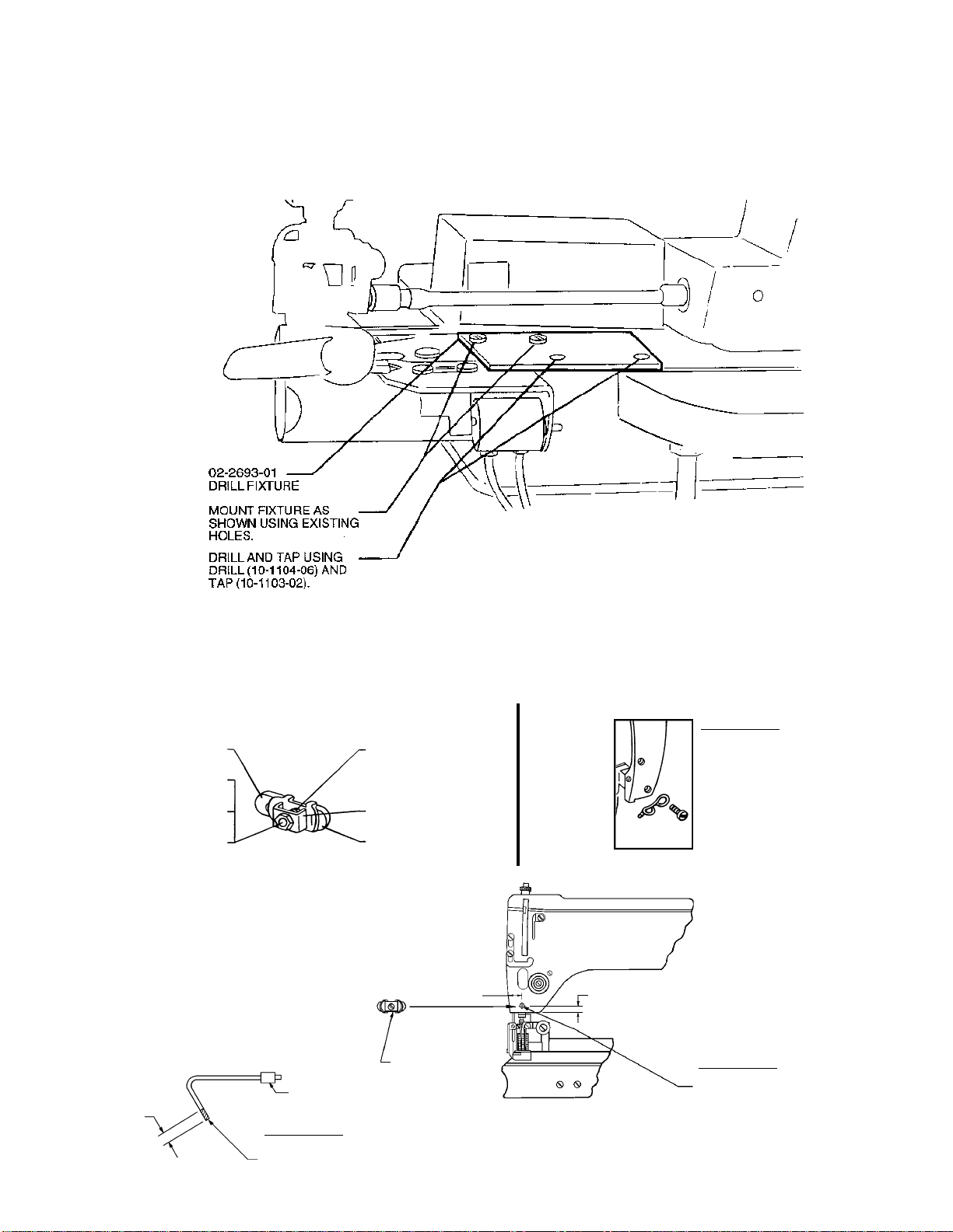
2. Drill and Tap mounting holes using appropriate drill fixture supplied. Refer to machine
drilling instructions shown in drawing INS-2355.
3. Mount tension release assembly and the thread tension discs assembly to the sewing
machine as shown in drawing INS-2353.
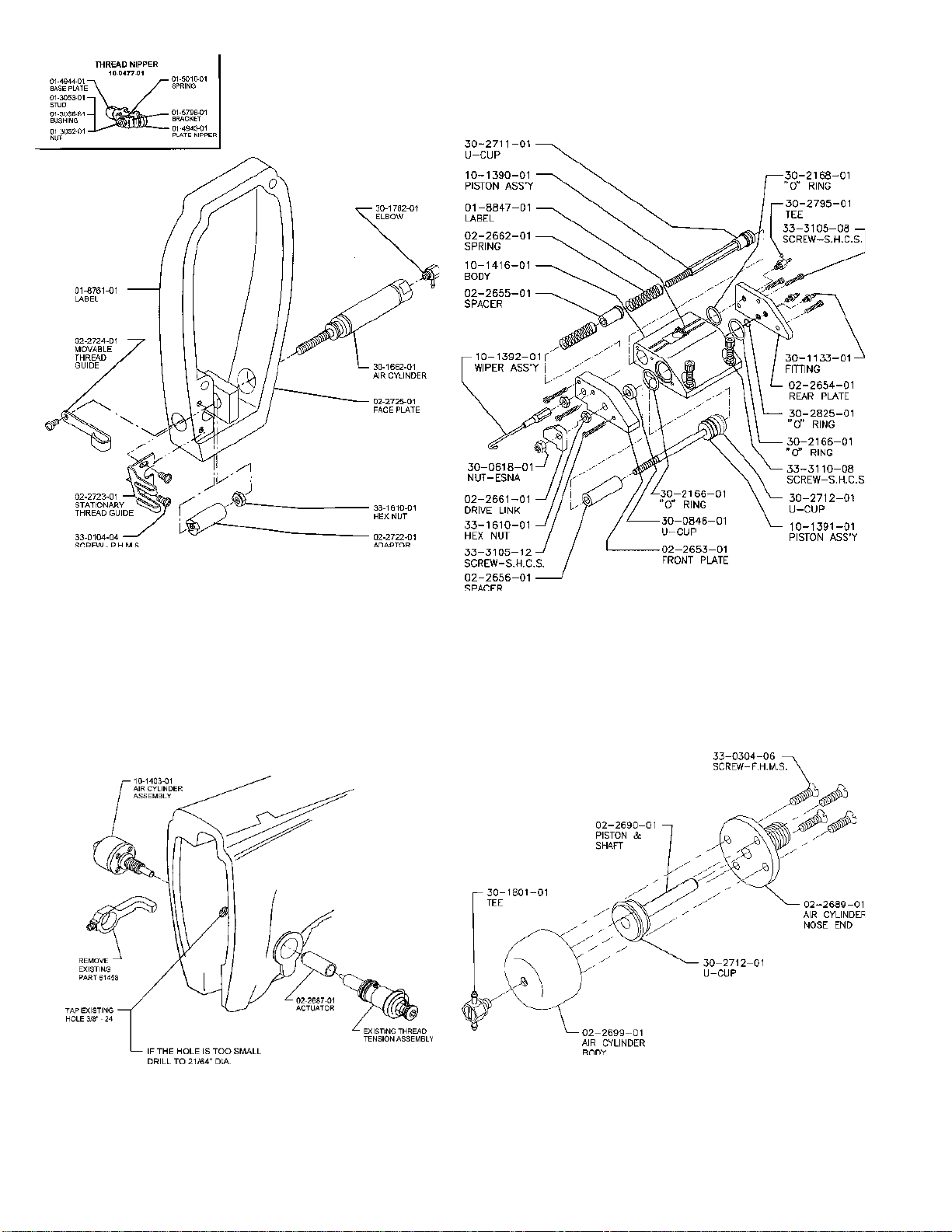
C. CUTTER AND WIPER ASSEMBLY
1. Remove from the machine throat plate and feed shaft clamp plate.
2. Rework clamp plate as shown in drawing INS-1630 and fasten to the machine.
3. Fasten cutter and wiper cylinder assembly to sewing machine bed.
4. Mount new throat plate assembly on the machine with original hook basket retaining
finger.
D. SOLENOID AIR VALVE CONTROL UNIT
1. Mount solenoid valve assembly in back of the machine bed as shown in INS-2379.
2. Mount foot lifter air cylinder assembly as shown in INS-2379.
E. NEEDLE COOLER
1. Fasten needle cooler tube to presser foot and roller housing bracket.
2. Mount treadle air valve assembly supplied between the motor and treadle arm.
F. FOLDER OPENER
1. Mount folder opener air cylinder assembly on bed of machine.
2. Assemble the folder opener assembly to the machine cylinder arm.
- 2 -

ML199-8
III. PRELIMINARY SETTINGS
NOTE: Do not connect the air supply at this time.
1. Set the machine head in the table and install "V" belt.
2. Time sewing machine to normal sewing conditions.
3. Connect all air lines as shown in circuit diagram drawing INS-2339.
4. Connect all electrical cables to the main control box.
5. Thread the sewing machine and sew on material being used on the operation.
IV. TRIMMER ADJUSTMENTS
A. TENSION RELEASE
Adjust puller for sufficient thread tail left on needle to start sewing on the next cycle.
B. CUTTER AND WIPER ASSEMBLY
1. Loosen the 10-32 nut on the cylinder shaft and adjust the knife travel so that the
cutting edge is about 1/16" past the cutting edge of the stationary blade.
2. Adjust the wiper to pass between the needle and the presser foot without striking
either. By loosening the two nuts on the cylinder shaft, the assembly will rotate
around the screw to position the wire hook. Bending may be necessary for proper
thread pickup.
3. With the power and air off, manually stimulate the trimmer sequence of operation
cycle several times to insure that the proper adjustments have been made.
C. SOLENOID AIR VALVE CONTROL UNIT
Turn power and air on. Set regulator to read 60 PSI and adjust the flow control of the
trim air cylinder to reduce bobbin spin.
D. FOOTLIFTER ASSEMBLY
Adjust footlifter cylinder for required amount of lift. Readjustment of footlift linkage may
be necessary.
- 3 -

ML199-9
E. NEEDLE COOLER
Adjust the flow control for the desired air flow to cool the needle and keep the throat plate
knife clean.
F. FOLDER OPENER
Adjust folder opener mounting bracket for required amount of opening.
V. TRIMMER SEQUENCE OF OPERATION
A. UNDERBED TRIMMER
The operation of the underbed trimmer is as follows:
1. Needle positioner stops with the needle thread positioned between the 5 and 6 o'clock
position across the hook. The needle is used for the reference point or 12 o'clock
position.
2. The movable knife is extended into the needle loop and in position to pick up the
bobbin thread.
3. The needle positioner moves the takeup and needle to up position.
4. The tension release, the pulloff and wiper cylinders operate after the positioner
reaches to up position.
5. Then the movable knife is returned to cut both needle and bobbin threads.
B. TENSION RELEASE
The needle thread tension is released so that the thread puller can pull off enough
thread to start the next sewing operation.
C. NEEDLE THREAD WIPER
The needle thread wiper pulls the needle thread above the foot before it is raised. If the
thread is trapped under the foot a long tail will be left at the start of the next sewing
opera-tion.
- 4 -

ML199-10
VI.TROUBLESHOOTING
PROBLEM PROBABLE CAUSE CORRECTIVE ACTION
Needle thread not cut.
Bobbin thread is cut
Positioner solenoid binding
Movable blade missed needle
loop
Binds in trimmer linkage
Remove bind
Check synchronizer timing
to see that trimmer is fired
at correct time
Locate and remove bind.
A light bind would slow it
enough to miss needle
loop
Both threads not cut not
picked up
Defective movable blade
Water in air lines
Defective solenoid air valve or air
cylinder
Defective needle positioner logic
Binds in trimmer linkage
Replace
Check filter. Remove
water from air lines
Repair or replace
Repair logic
Locate and remove bind
Both threads picked up not
cut
Defective movable or stationary
blade
Stroke misadjusted failing to
reach cutting position
Replace
Readjust
Needle thread cut short Pulloff cylinder improperly
adjusted Readjust
Long tail left on top side at
start of sewing Wiper not operating or incorrectly
positioned causing thread to be
trapped under foot
Repair or reposition thread
wiper as required
Bobbin thread is cut short
Bobbin tension too tight
Bobbin thread slipped out of hook
on case
Bobbin case without hook being
used
Lossen bobbin tension as
much as possible
Run bobbin thread
through hook
Replace with correct
bobbin case
- 5 -
PULLOFF ASSEMBLY
MODEL 199 U.S. 63900
80-0503-01
INS-2377C ML199-11
INS-2337E
TRIM AND WIPER ASSEMBLY
MODEL 199 FOR U.S. 63900
80-0514-01
TENSION RELEASE ASSEMBLY
MODEL 199 U.S. 63900
80-0517-01
INS-2353C
-6-
INS-2354A
AIR CYLINDER THREAD RELEASE ASSEMBLY
MODEL 199 U.S. 63900
10-1403-01
INS-765B
63900 M, T, W
STEP 1.
REMOVELOWERNEEDLE
THREADEYELET& SCREW
ASSHOWN.
STEP 2.
REPLACE EYELET & SCREW
WITHTHREADNIPPER
ASSEMBLY(10-0477-01).
THREAD NIPPER
01-5010-01
SPRING
01-5798-01
BRACKET
01-4943-01
PLATENIPPER
01-4944-01
BASEPLATE
01-3053-01
STUD
01-3038-61
BUSHING
01-3052-01
NUT
.187
UNION SPECIAL
#61453-6
61400 M, T, W
CUT OFF SHADED AREA
61400 M, T, W
STEP 1.
DRILLAND TAP HOLESQUARE (90O)TOSURFACE
OFMACHINEUSING#31 DRILL AND UNION
SPECIAL #V107 TAP.
STEP 2.
MOUNTTHREADNIPPERASSEMBLY (10-0477-01).
.312
.656
10-0477-01
THREADNIPPER
- 7 -
ML199-12
INS-2355A
DRILLING INSTRUCTIONS / DRILL FIXTURE KIT
MODEL 199 FOR U.S. 63900
10-1405-01
DRILLING AND MOUNTING INSTRUCTIONS
THREAD NIPPER ASSEMBLY 61400 M, T, W - 63900 M, T, W
REWORK - TAKEUP SPRING THREAD WIRE 61400 M, T, W

INS-2335B
FOLDER ASSEMBLY
MODEL 199 FOR U.S. 63900
80-0513-01
33-3108-12
SCREWS.H.C.S. 30-2553-01
AIRCYLINDER
30-1783-01
ELBOW
02-2702-01
BRACKET-SOL.
MOUNT
33-3105-08
SCREWS.H.C.S.
02-2652-01
BLOCK
33-0706-20
SCREWFIL.H.M.S.
NOTE:
ALL PARTS NOT IDENTIFIED ARE
SUPPLIED BY UNION SPECIAL.
SEE UNION SPECIAL MANUAL.
INS-1667C
ACCUSTOP
SYNCHRONIZER ADAPTER MOUNTING FOR U.S. 63900
80-0323-51
-8-
INS-1630-1
ML199-13
REWORK FEED SHAFT CLAMP PLATE
UNION SPECIAL
#63939F
CHAMFER THIS
CORNER APPROX.
AS SHOWN
MACHINED DOTTED
AREA TO THE
COUNTERBORES


INS-2379B
MODEL 199
(MACHINE REAR VIEW)
FILTER,
REGULATOR,
GAUGE
ASSEMBLY
TENSION
RELEASE
ASSEMBLY
SOLENOID
VALVE
ASSEMBLY
NEEDLE
COOLER
ASSEMBLY
FOOTLIFTER
ASSEMBLY
NEEDLE COOLER ASSEMBLY
80-0204-03
01-4936-
01
TUBE
01-4938-
01
CLAMP
30-1064-
01
SCREW
ML199-16
-11-

-12-
THROAT PLATE ASSEMBLY
MODEL 199 FOR U.S. 673900
80-0515-01
INS-2341D
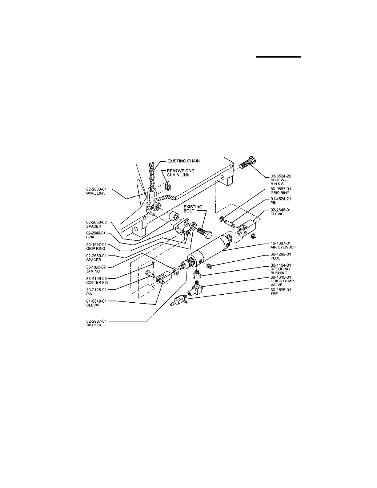
FOOTLIFTER ASSEMBLY
MODEL 199 FOR U.S. 63900
80-0180-125
ML199-17
ML-000-5B
30-1160-01
BONNET
30-1108-01
FILTER ELEMENT
5 MICRON 30-1561-01
BOWL
30-1085-01
BOWL
30-1610-01
LUBRICATOR
REPAIR KIT
(CONTAINS ITEMS
18,20,22)
30-2788-01
FILTER/REG.
REPAIR KIT
(CONTAINS ITEMS
3,4,5,6,7,8,10,14,16)
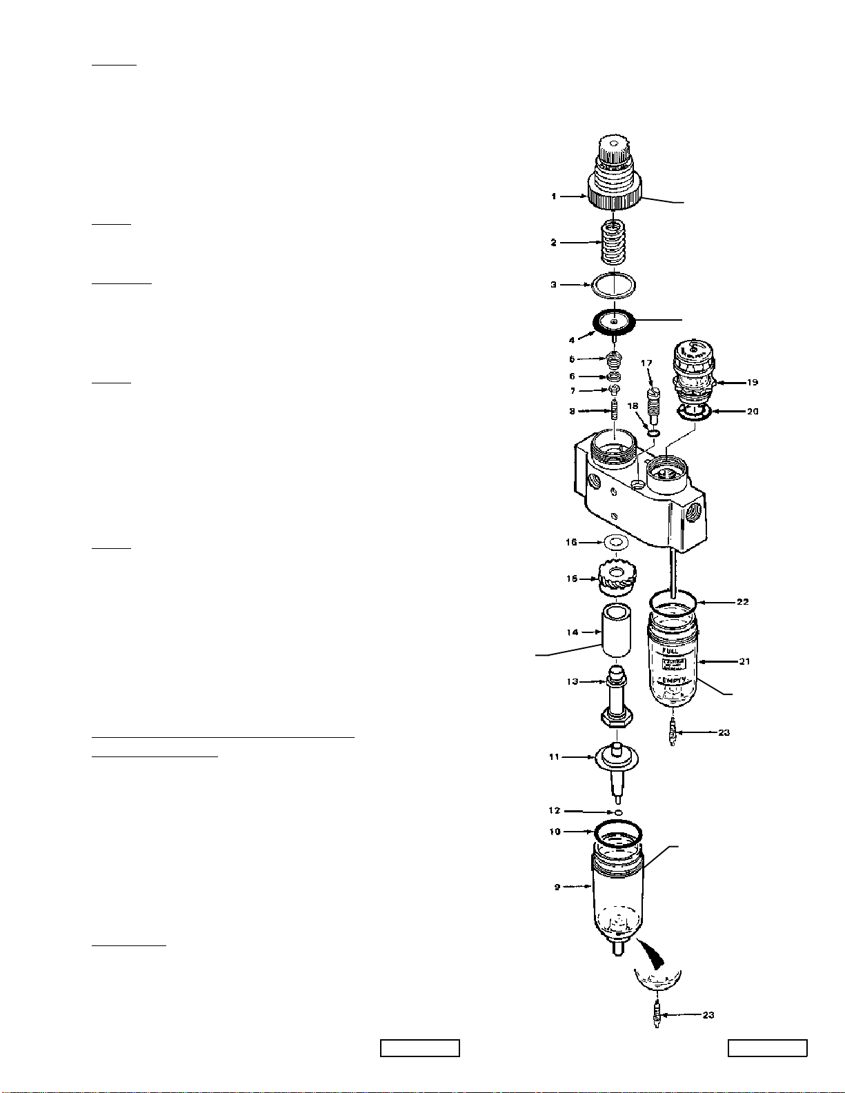
INS-2100-2A INS-2100-1B
FILTER, REGULATOR, AND LUBRICATOR
30-2347-01
FILTER/REGULATOR
OPERATION
AIRENTERSTHEINTEGRALFILTER/REGULATORUNITANDISDIRECTEDDOWNWARD
THROUGHASET OF LOUVERS (10) TOIMPART A WHIRLING ACTION. THIS CENTRI-
FUGALACTIONCAUSESLIQUIDPARTICLESTO BE SEPARATEDFROMTHEAIRSTREAM
ANDSETTLETOTHE BOTTOM OF THE BOWL. ACCUMULATED LIQUID IS DRAINED
MANUALLY (15).
AIRTHENPASSES THROUGH THE SINTERED BRONZE FILTERELEMENT(11) WHERE
SMALLERSIZEFOREIGNPARTICLES ARE REMOVED.
THECLEANAIRPASSES THROUGH THE VALVE (5,6,7,8) OF THE REGULATOR AND IS
CONTROLLEDTOAPRESSURE,DETERMINEDBYTHE ADJUSTMENT OF THE REGULATOR.
PRESSUREISINCREASEDBY ROTATINGTHEKNOBCLOCKWISE,ORDECREASEDBY
ROTATING THE KNOBCOUNTERCLOCKWISE.
CAUTION: THIS MINIATURE INTEGRAL FILTER/REGULATOR SHOULD NOT BE USED IN
APPLICATIONS WHICH MAY EXCEED 250 PSIG. DURING MAINTENANCE PERIODS,
INSPECT AND CLEAN EACH PART CAREFULLY, USING ONLY CLEAR, WARM
WATER OR KEROSENE. DO NOT USE SOLVENTS AS THE POLYCARBONATE BOWL
MAY BE DAMAGED.
MAINTENANCE:
REGULATORSECTION: DISASSEMBLETHEREGULATORSECTION ASFOLLOWS: TURNOFF
AIRSUPPLY. TURNTHEADJUSTINGKNOBCOUNTERCLOCKWISETORELIEVE COMPRESSION
ONTHEREGULATING SPRING (2). UNSCREW THE BONNET (1),REMOVETHEREGULATING
SPRING (2), AND PISTON ASSEMBLY (4). UNSCREW THE VALVE SEAT (5) WITH A 3/8"
SOCKETAND REMOVE THE VALVEASSEMBLY (7) AND VALVESPRING (8).
CLEANAND INSPECT EACH PARTFORWEAR OR DAMAGE. REPLACE IF NECESSARY.
CAUTION: WHEN REASSEMBLING, VALVE SEAT (5) SHOULD NOT BE TIGHTENED TO MORE
THAN 4 TO 6 INCH POUND TORQUE. BONNET ASSEMBLY (1) SHOULD BE
TIGHTENED 50 TO 60 INCH POUNDS TORQUE.
MANUALDRAINFILTER SECTION: TOSERVICETHEFILTER SECTION SHUT OF THEAIR
PRESSURE. UNSCREWBOWL ASSEMBLY (14) AND REMOVE "O" RING(9) UNSCREW STUD (13)
ANDFROMTHE STUD REMOVE FILTERELEMENT(11),LOUVER(10)ANDGASKETS(12).
THEFILTERELEMENTSHOULDBECLEANEDPERIODICALLYWITHKEROSENEANDBLOWN
OUTWITHCOMPRESSEDAIR.
AFTERCLEANING,INSPECTEACH PARTCAREFULLY,REPLACEANYDAMAGEDPARTS. WHEN
REASSEMBLING,TIGHTENSTUD(13)TO5 TO 10 INCHPOUNDSTORQUE.
LUBRICATOR
CAUTION: THIS UNIT HAS A POLYCARBONATE BOWL.
1. BESUREIT IS NOT MOUNTED WHERE TEMPERATURESOF125 FOR MORE WILL BE
NEARIT, OR ON A LINE WHERE AIR PRESSURE EXCEEDS 150PSI.
2. BEWAREOFCONDITIONS,FUMESANDFLUIDSTHAT WILL HARM THE TRANSPARENT
BOWL.
3. TOCLEANBOWL,RINSEOR WIPE WITH A PETROLEUM SOLVENTONLY, SUCH AS
KEROSENE,ORHOUSEHOLD DISHWASHERDETERGENT.
4. DO NOT USE NEAR, OR CLEAN WITH SUCH MATERIALSASACETONE,ALCOHOL,
BENZENE,DIOXANE,ETHELACETATE,LACQUERTHINNER,TOLUENE,CHLORIDE,
CARBONTETRACHLORIDE,ALKALIES,AMINES,ESTERS,KETONESAND AROMATIC
HYDROCARBONS.
5. DO NOT INSTALLON A COMPRESSED AIR LINE WHERE THE COMPRESSOR IS LUBRI-
CATEDWITH,ORTHEAIRCONTAINS, A SYNTHETIC, FIRE-RESISTANT LUBRICANT.
IMPORTANT: INSTALLATIONS INSTRUCTIONS FOR LUBRICATORS.
WHERE AND HOW TO INSTALL:
1. INSTALLASCLOSE AS FEASIBLE TO EQUIPMENT TOBELUBRICATED WITHAIR
FLOWINGINANDOUTPORTSSO MARKED.
2. TOFILLTHELUBRICATOR,TURNOFFAIRPRESSURE,REMOVEBOWLANDFILL.
3. POURINONLYCLEANOIL. SAE 10 OR LIGHTER USUALLYIS BEST,NEVER USE
ONEOFTHE FOLLOWING OILS: CELLULUBE #150 AND #220, KANOKROIL,
KEYSTONE PENETRATING OIL#2ORPYDRAULAC.
4. AS SOON AS AIR PRESSURE REBUILDS INSIDETHEBOWL, OIL WILL DRIP THROUGH
THESIGHTGAUGE. CONTROLTHERATE OF OIL ENTERINGTHEAIRSTREAMBY
TURNINGTHEADJUSTMENTSCREWDOWNTOGIVE LESS OIL AND UP TOGIVEMORE
OIL. THISIS A UNIQUE LUBRICATOR. YOUADJUST THIS TYPE SO THAT WHILE
THESMALLESTAMOUNTOFAIRISFLOWINGTHROUGHIT YOU GET THE DESIRED
AMOUNTOFOILFORTHATFLOW. THE MORE THE AIR FLOW INCREASES, THE MORE
OILYOUWILL NEED AND THE MORE YOU WILLGETAUTOMATICALLY.
HOWTOMAINTAIN:
1. PERIODICALLYCLEANADJUSTING SCREW NEEDLE VALVEAND SEATBY SWISHING A
CLEANERAND BLOWING OFF WITH AIR.
2. DRAIN OFF ANYCONTAMINANTSORWATERIFTHEYSETTLEINTHEBOTTOMOF
THEBOWL.
30-2797-01
Table of contents
Other CLINTON INDUSTRIES Trimmer manuals

Popular Trimmer manuals by other brands

Truper
Truper COS-26X manual

Chicago Electric
Chicago Electric 09662 Assembly and operating instructions

Worx
Worx WG286E Safety and operating manual

Bosch
Bosch AHS 41 ACCU Operating instrucctions

Einhell Royal
Einhell Royal ERT 550/1 V Directions for use

Black & Decker
Black & Decker LHT120 instruction manual


