ClipperCreek PEDESTAL User manual

innovative infrastructure for
electric and hybrid vehicles
PEDESTAL INSTALLATION GUIDE
TESLA®WALL CONNECTOR & CLIPPERCREEK HCS
ClipperCreek
,Inc
.

Page 2
ClipperCreek,Inc.
PEDESTAL INSTALLATION GUIDE
PLEASE NOTE
This user’s manual includes the latest information at the time of printing.
ClipperCreek, Inc. reserves the right to make changes to this product without further notice. Changes or modications to this product by other than an
authorized service facility may void the product warranty.
TESLA® and ® are registered trademarks of TESLA® Motors, Inc. and are used under license. TESLA® Motors, Inc. is not
responsible for the content or accuracy of any statements or instructions made in this document and disclaims any responsibility for such statements
or instructions.
If you have questions about the use of this product, contact your customer service representative. Refer to the Customer Support section located in
this guide.
TESLA® Wall Connector Pedestal Installation Guide, Version 2, January 2022
Copyright © 2014 ClipperCreek, Inc.
All rights reserved. Printed in the USA.
Download or view the most recent version of this Installation Guide at:
ClipperCreek.com/installation-manuals

Page 3
ClipperCreek,Inc.
PEDESTAL INSTALLATION GUIDE
TABLE OF CONTENTS
SAFETY INSTRUCTIONS 4
INSTALLATION CONFIGURATIONS AND TOOLS REQUIRED 4
INSTALLATION REQUIREMENTS 8-9
PACKING LISTS 10
OPTIONAL ORDERABLE ITEMS 11
INSTALLATION CHAPTERS:
MAIN PEDESTAL 12-14
TESLA® WALL CONNECTOR 15-21
CLIPPERCREEK HCS 22-25
CLIPPERCREEK, INC. CUSTOMER SUPPORT 26
CLIPPERCREEK, INC. WARRANTY INFORMATION 27

Page 4
ClipperCreek,Inc.
PEDESTAL INSTALLATION GUIDE
IMPORTANT SAFETY INSTRUCTIONS
BEFORE YOU BEGIN: Read these instructions completely, including the Safety Instructions. If you have questions about the use of this product,
contact your Service Representative.
NOTE TO THE INSTALLER: Be sure to leave these instructions with the user.
NOTE TO THE USER: Keep these instructions for further reference.
The TESLA® Wall Connector and ClipperCreek Electric Vehicle Supply Equipment (EVSE or “charging station”) are designed with the safety
concerns of the end user as an utmost priority; however, the following safety precautions must be read and followed:
• The charging station and electrical wiring should be installed by a qualied electrician in accordance with local electrical codes and
ordinances.
• Grounding Instructions - The charging station should be connected to a grounded, metal, permanent wiring system; or an
equipment-grounding conductor should be run with circuit conductors and connected to a grounding terminal or lead on the
charging station. Connections to the charging station should comply with all local electrical codes and ordinances.
• Call your local service provider anytime a procedural question arises; DO NOT attempt to perform a procedure you are unsure of.
• Read all installation instructions carefully before performing the pedestal and charging station installation.
EVSE PEDESTAL INSTALLATION GUIDE: TESLA® WALL CONNECTOR AND
CLIPPERCREEK HCS CONFIGURATIONS
• Single TESLA®
• Dual TESLA®
• Single ClipperCreek HCS
• Dual ClipperCreek HCS
• Combo TESLA® and ClipperCreek
TOOLS REQUIRED FOR ASSEMBLING THE TESLA® WALL CONNECTOR MOUNTING
PLATE AND PEDESTAL
THE FOLLOWING TOOLS ARE REQUIRED FOR THE INSTALLATION AND ASSEMBLY OF THE TESLA® WALL CONNECTOR MOUNTING
PLATE COMPONENTS.
• T20 Torx driver
• T27 Torx Driver
• 5/16” Box Wrench
• Ratchet wrench with 8mm Socket or 5/16” Nut Driver
• 5/16” Flathead Screwdriver (for Ground Block Lug)
• 1 ¼” (32mm) hole saw
• #2 Phillips Head Screwdriver
• 5/16” Flathead Screwdriver (for Ground Block Lug)
• Box Wrench (appropriately sized for the Anchor Nuts)
TOOLS REQUIRED FOR ASSEMBLING CLIPPERCREEK HCS CHARGING STATION AND
PEDESTAL
THE FOLLOWING TOOLS ARE REQUIRED FOR THE INSTALLATION AND ASSEMBLY OF THE CLIPPERCREEK HCS PEDESTAL
COMPONENTS.
• L-shape T27 Torx Driver (there are some tight spaces, advise using both the long and short T27’s for faster assembly)
• #2 Phillips Head Screwdriver
• 5/16” Flathead Screwdriver (for Ground Block Lug)
• Box Wrench (appropriately sized for the Anchor Nuts)

Page 5
ClipperCreek,Inc.
PEDESTAL INSTALLATION GUIDE
Single TESLA® Wall Connector,
Single ClipperCreek HCS
TESLA® Wall Connector and
ClipperCreek HCS Combo
Dual TESLA® Wall Connector,
Dual ClipperCreek HCS
NOTE TO INSTALLER
REGARDING THE
COMBO CONFIGURATIONS:
FOR EASIEST ASSEMBLY INSTALL TESLA® Wall
Connector PRIOR to the
ClipperCreek HCS

Page 6
ClipperCreek,Inc.
PEDESTAL INSTALLATION GUIDE
TESLA® WALL CONNECTOR SINGLE AND DUAL MOUNT CONFIGURATION
DIMENSIONS

Page 7
ClipperCreek,Inc.
PEDESTAL INSTALLATION GUIDE
CLIPPERCREEK HCS SINGLE AND DUAL MOUNT CONFIGURATION DIMENSIONS

ClipperCreek,Inc.
PEDESTAL INSTALLATION GUIDE
INSTALLATION REQUIREMENTS
Refer to the EVSE documentation to determine the appropriate circuit breaker current capacity. All conductors must be appropriately sized for the
EVSE current capacity, in accordance with local and NEC electrical codes.
REQUIRED EQUIPMENT FOR A SINGLE-MOUNT PEDESTAL WITH ONE TESLA® WALL CONNECTOR (ONE EVSE PEDESTAL):
• One (1) TESLA® Wall Connector (EVSE). NOTE: The TESLA® Wall Connector comes with a Cable Organizer for Wall Mounting
Purposes only. This cable organizer is not utilized on the Pedestal Mounting System.
• One (1) ClipperCreek TESLA® EVSE Pedestal Kit, ClipperCreek part number 0300-00-022.
• One (1) dedicated 208 or 240 VAC branch circuits.
• One (1) circuit breaker, appropriately sized with respect to the charging capacity of each EVSE.
• Two (2) Live Line conductors with enough length to comfortably pull all the way through and above the top of the pedestal.
• One (1) Ground Line conductor with enough length to comfortably pull all the way through and above the top of the pedestal.
• Conduit sized to t all three conductors.
• Four (4) Anchor Bolts with Nuts and Washers
REQUIRED EQUIPMENT FOR A DUAL-MOUNT PEDESTAL WITH TWO TESLA® WALL CONNECTORS (TWO EVSE’S PER PEDESTAL):
• Two (2) TESLA® Wall Connectors (EVSE’s). NOTE: The TESLA® Wall Connector comes with a Cable Organizer for Wall
Mounting Purposes only. This cable organizer is not utilized on the Pedestal Mounting System.
• One (1) ClipperCreek TESLA® EVSE Pedestal Kit, ClipperCreek part number 0300-00-022.
• One (1) ClipperCreek Dual-Mount TESLA® Mounting Plate Kit, ClipperCreek part number 0300-00-021.
• Two (2) dedicated 208 or 240 VAC branch circuits.
• Two (2) circuit breakers, appropriately sized with respect to the charging capacity of each EVSE.
• Two pairs (2x2) Live Line conductors (one pair for each EVSE) with enough length to comfortably pull all the way through and
above the top of the pedestal.
• Two (2) Ground Line conductors (One for each EVSE) or a single bonded Ground Line with enough length to comfortably pull all
the way through and above the top of the pedestal.
• Conduit sized to t all Live Line and Ground Line conductors.
• Four (4) Anchor Bolts with Nuts and Washers
REQUIRED EQUIPMENT FOR A COMBO DUAL-MOUNT PEDESTAL WITH ONE TESLA® WALL CONNECTOR AND ONE HCS CHARGING
STATION (TWO EVSE’S PER PEDESTAL):
• One (1) TESLA® Wall Connector (EVSE). NOTE: The TESLA® Wall Connector comes with a Cable Organizer for Wall Mounting
Purposes only. This cable organizer is not utilized on the Pedestal Mounting System.
• One (1) ClipperCreek HCS EVSE Pedestal Kit, ClipperCreek part number 0300-00-019.
• One (1) ClipperCreek HCS Charging Station (EVSE), part number depends on amperage selected.
• One (1) ClipperCreek Dual-Mount TESLA® Mounting Plate Kit, ClipperCreek part number 0300-00-021.
• Two (2) dedicated 208 or 240 VAC branch circuits.
• Two (2) circuit breakers, appropriately sized with respect to the charging capacity of each EVSE.
• Two pairs (2x2) Live Line conductors (one pair for each EVSE) with enough length to comfortably pull all the way through and
above the top of the pedestal.
• Two (2) Ground Line conductors (One for each EVSE) or a single bonded Ground Line with enough length to comfortably pull all
the way through and above the top of the pedestal.
• Conduit sized to t all Live Line and Ground Line conductors.
• Four (4) Anchor Bolts with Nuts and Washers
Page 8

Page 9
ClipperCreek,Inc.
PEDESTAL INSTALLATION GUIDE
REQUIRED EQUIPMENT FOR A SINGLE-MOUNT PEDESTAL WITH ONE CLIPPERCREEK HCS CHARGING STATION (ONE EVSE PER
PEDESTAL):
• One (1) ClipperCreek HCS EVSE Pedestal Kit, ClipperCreek part number 0300-00-019.
• One (1) ClipperCreek HCS Charging Station (EVSE), part number depends on amperage selected.
• One (1) dedicated 208 or 240 VAC branch circuit.
• One (1) circuit breaker appropriately sized for the EVSE charging capacity.
• Two (2) Live Line conductors with enough length to comfortably pull all the way through and above the top of the pedestal.
• One (1) Ground Line conductor with enough length to comfortably pull all the way through and above the top of the pedestal.
• Conduit sized to t all three conductors.
• Four (4) Anchor Bolts with Nuts and Washers
REQUIRED EQUIPMENT FOR A DUAL-MOUNT PEDESTAL WITH TWO CLIPPERCREEK HCS CHARGING STATIONS (TWO EVSE’S PER
PEDESTAL):
• One (1) ClipperCreek HCS EVSE Pedestal Kit, ClipperCreek part number 0300-00-019.
• One (1) ClipperCreek Dual-Mount HCS Pedestal Kit, ClipperCreek part number 0300-00-020.
• Two (2) ClipperCreek HCS Charging Stations (EVSEs), part number depends on amperage selected.
• Two (2) dedicated 208 or 240 VAC branch circuits.
• Two (2) circuit breakers, appropriately sized with respect to the charging capacity of each EVSE.
• Two pairs (2x2) Live Line conductors (one pair for each EVSE) with enough length to comfortably pull all the way through and
above the top of the pedestal.
• Two (2) Ground Line conductors (One for each EVSE) or a single bonded Ground Line with enough length to comfortably pull all
the way through and above the top of the pedestal.
• Conduit sized to t all Live Line and Ground Line conductors.
• Four (4) Anchor Bolts with Nuts and Washers

Page 10
ClipperCreek,Inc.
PEDESTAL INSTALLATION GUIDE
PACKING LISTS
0300-00-022 TESLA® PEDESTAL KIT, STANDARD 4 FOOT, SINGLE-MOUNT
PART NUMBER QTY DESCRIPTION
1003-0043 1 Pedestal Metalwork, Cap with Front and Rear Flange NOTE: this item may already be
attached to the top of the pedestal.
1003-0023 2 Pedestal Metalwork, Base Cover
1003-0035 1 Pedestal Metalwork, 4-Foot Post
1003-0037 1 Pedestal Metalwork, Hole Cover Plate
1003-0042 1 Pedestal Metalwork, TESLA® Wall Connector Mounting Plate
4000-0010 4 Machine Screw, Tapered Flat Head, 6-32 Size, 3/8” Length, Phillips
4000-0011 4 Machine Screw, Tapered Flat Head, 1/4-20 Size, 3/4” Length, T27 Torx
4000-0012 2 Machine Screw, Button Head, 1/4-20 Size, 1” Length, T27 Torx
4001-0008 2 Hex Nut, 18-8 Stainless Steel, 5/16”-18 Thread, 1/2” Width, 17/64” Height
4002-0002 2 Washer, Galvanized Steel, Neoprene Bonded Seal, 1/4” ID, 5/8” OD
4002-0008 2 Washer, 18-8 Stainless Steel, 5/16” screw size, 11/32” ID, 11/16” OD
4015-0000 4 Plug, Plastic Push-In, 1-3/32” ID, 1-7/32” OD
4015-0001 2 Plug, Plastic Push-In, 1-3/8” ID, 1-1/2” OD
4015-0004 2 Plug, Plastic Push-In, 7/8” ID, 1” OD
0300-00-019 HCS PEDESTAL KIT, STANDARD 4 FOOT, SINGLE-MOUNT
PART NUMBER QTY DESCRIPTION
1001-0015 1 Holster, gray polycarbonate
1003-0014 1 Pedestal Metalwork, Cap with Rear Flange NOTE: this item may already be attached to
the top of the pedestal.
1003-0023 2 Pedestal Metalwork, Base Cover
1003-0035 1 Pedestal Metalwork, 4-Foot Post
1003-0037 1 Pedestal Metalwork, Hole Cover Plate
1003-0039 1 Pedestal Metalwork, HCS Charging station Mounting Plate
4000-0005 2 Machine Screw, Pan Head, 8-32, ½” Length, Phillips
4000-0010 4 Machine Screw, Tapered Flat Head, 6-32 Size, 3/8” Length, Phillips
4000-0011 3 Machine Screw, Tapered Flat Head, 1/4-20 Size, 3/4” Length, T27 Torx
4000-0012 2 Machine Screw, Button Head, 1/4-20 Size, 1” Length, T27 Torx
4000-0019 2 Machine Screw, Button Head, 1/4-20 Size, 2” Length, T27 Torx
4002-0001 2 Washer, #8, Zinc, 3/16”ID, 7/16” OD
4002-0002 4 Washer, Galvanized Steel, Neoprene Bonded Seal, 1/4” ID, 5/8” OD
4002-0004 1 Washer, Liquid Tight Sealing, Thermoplastic, ½”
4013-0008 or 4013-0009 1 Pedestal Conduit Assembly, Standard 90 degree 1/2” NPT Fitting Conduit for
HCS-60 (or higher) and 3/8” NPT for HCS-40 (or lower)
4015-0000 4 Plug, Plastic Push-In, 1-3/32” ID, 1-7/32” OD
4015-0001 2 Plug, Plastic Push-In, 1-3/8” ID, 1-1/2” OD
4015-0004 2 Plug, Plastic Push-In, 7/8” ID, 1” OD

Page 11
ClipperCreek,Inc.
PEDESTAL INSTALLATION GUIDE
OPTIONAL ORDERABLE ITEMS
0300-00-021 TESLA® WALL CONNECTOR DUAL-MOUNT KIT FOR STANDARD 4 FOOT PEDESTAL (OPTIONAL)
PART NUMBER QTY DESCRIPTION
1003-0042 1 Pedestal Metalwork, TESLA® Wall Connector Mounting Plate
4000-0011 2 Machine Screw, Tapered Flat Head, 1/4-20 Size, 3/4” Length, T27 Torx
4001-0008 2 Hex Nut, 18-8 Stainless Steel, 5/16”-18 Thread, 1/2” Width, 17/64” Height
4002-0008 2 Washer, 18-8 Stainless Steel, 5/16” screw size, 11/32” ID, 11/16” OD
0300-00-020 HCS DUAL-MOUNT KIT FOR STANDARD 4 FOOT PEDESTAL (OPTIONAL)
PART NUMBER QTY DESCRIPTION
1001-0015 1 Holster, gray polycarbonate
1003-0015 1 Pedestal Metalwork, Cap without Rear Flange
1003-0039 1 Pedestal Metalwork, HCS Charging station Mounting Plate
4000-0005 2 Machine Screw, Pan Head, 8-32, ½” Length, Phillips
4000-0011 1 Machine Screw, Tapered Flat Head, 1/4-20 Size, 3/4” Length, T27 Torx
4000-0012 2 Machine Screw, Button Head, 1/4-20 Size, 1” Length, T27 Torx
4000-0019 2 Machine Screw, Button Head, 1/4-20 Size, 2” Length, T27 Torx
4002-0001 2 Washer, #8, Zinc, 3/16”ID, 7/16” OD
4002-0002 4 Washer, Galvanized Steel, Neoprene Bonded Seal, 1/4” ID, 5/8” OD
4002-0004 1 Washer, Liquid Tight Sealing, Thermoplastic, ½”
4013-0008 or 4013-0009 1 Pedestal Conduit Assembly, Standard 90 degree 1/2” NPT Fitting Conduit for
HCS-60 (or higher) and 3/8” NPT for HCS-40 (or lower)
0300-06-000 120V GROUND FAULT RECEPTACLE KIT (OPTIONAL)*
PART NUMBER QTY DESCRIPTION
4015-0002 1 Plug, Knockout Bushing, 1.109” OD, 3/4” Trade Size Aperture
4301-0000 1 GFCI Ground Fault Receptacle, 15A, 125V, NEMA 5-15R, Single Socket with Switch
4301-0001 1 Gang Box, Single, Silver Metal
4301-0002 1 Weatherproof Receptacle Cover, Clear, Single Gang, 2-3/4” Depth
* The Ground Fault Receptacle Kit includes a 120VAC GFCI receptacle and housing. It may be installed at the knock-outs located
24 inches above the base on either side of the pedestal.

Page 12
ClipperCreek,Inc.
PEDESTAL INSTALLATION GUIDE: MAIN PEDESTAL
MAIN PEDESTAL SETUP – BOTH HCS & TESLA® INSTALLATIONS REQUIRE THESE STEPS
1. CONCRETE PAD REQUIREMENTS
The location, dimensions, and composition of the concrete pad underlying the pedestal should always adhere to local building codes. The following
dimensions are minimum recommended values. Always verify that installation plans adhere to local code requirements prior to proceeding.
• The pad area must be a minimum of 18” to a side.
• The concrete must be poured a minimum depth of 18”.
• If there is no bumper block, the center of the pedestal base should be situated 36” behind the curb.
• If a bumper block is in place, the center of the pedestal base should be situated 12” behind the curb.
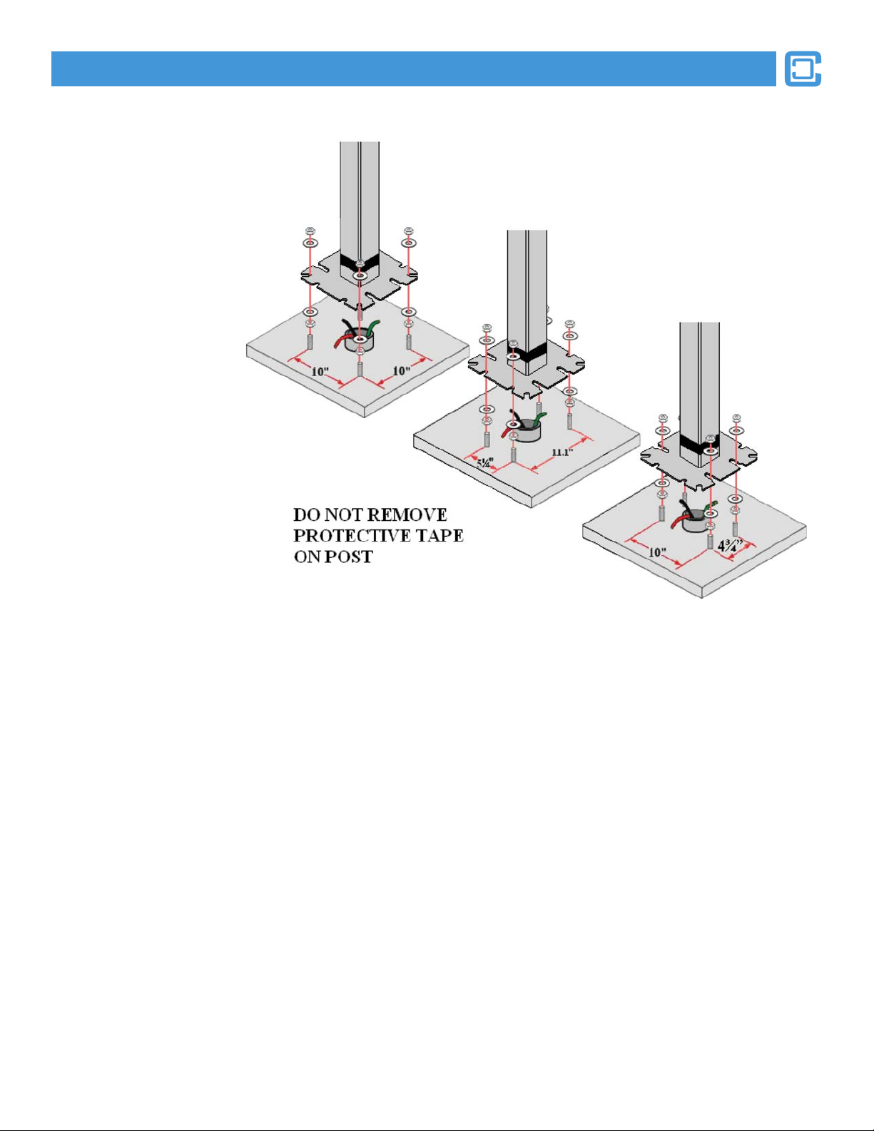
2. ANCHOR BOLT PLACEMENT
A minimum of four (4) anchor bolts must be embedded in the concrete pad for the purposes of securing the pedestal post. The pedestal base is de-
signed to permit the anchor bolts to be arranged in many congurations, including the following:
Use the Pedestal Base Pattern Template: To better facilitate the installation of the anchor bolts, a
cardboard template in the shape of the pedestal base is included in the pedestal kit. This template is
provided as a knock-out piece on the back of the cardboard box in which the cover plate is packaged.
The template is specic for two bolt patterns: the standard 10” x 10” pattern and an alternate 5.25” x
11.1” rectangular pattern.
Page 13
ClipperCreek,Inc.
PEDESTAL INSTALLATION GUIDE: MAIN PEDESTAL
For the Standard 10” Square
Pattern: Arrange four (4) 1/2”
or 3/8” anchor bolts in a 10”
square pattern. This placement
corresponds to the corner
cutouts in the pedestal base.
For theAlternate 5.25” x 11.1”
Rectangular Pattern: Arrange
four (4) 3/8” anchor bolts in a
5.25” by 11.1” rectangular
pattern. This placement
corresponds to the short inner
cutouts in the pedestal base.
For theAlternate 10” x 4.75”
Rectangular Pattern:
Arrange four (4) 1/2” anchor
bolts in a 10” by 4.75”
rectangular pattern. This
placement corresponds to fall
within the long inner cutouts in
the pedestal base.
Maximum Anchor Bolt
Height: The anchor bolts should
not protrude more than 3” above
the surface of the concrete pad.
3. MOUNTING THE PEDESTAL POST
Once the concrete pad with anchor bolts has been prepared and the three service conductors have been pulled through the underground conduit, the
pedestal post may be placed.
• Feed the three service conductors up through the inside of the pedestal post. The conductors must be of sufcient length to pass
beyond the top of the pedestal so that nal connections can be worked with comfortably at a later step.
• Align the pedestal post base notches with the four anchor bolts and ease it into place.
NUTS AND WASHERS MAY BE USED UNDER THE PEDESTAL BASE TO ADJUST THE VERTICAL ALIGNMENT OF
THE PEDESTAL SHOULD THE CONCRETE PAD NOT BE LEVEL.
• Secure the pedestal post base to the concrete anchor bolts using appropriately sized nuts and washers.
• The anchor bolts, nuts and washers used for the installation of the pedestal base are not included in the pedestal kit and must be
purchased separately.
NOTE: DO NOT remove the tape at the bottom of the pedestal. This tape is provided for nish and weather protection of the pedestal post.
Page 14
ClipperCreek,Inc.
PEDESTAL INSTALLATION GUIDE: MAIN PEDESTAL
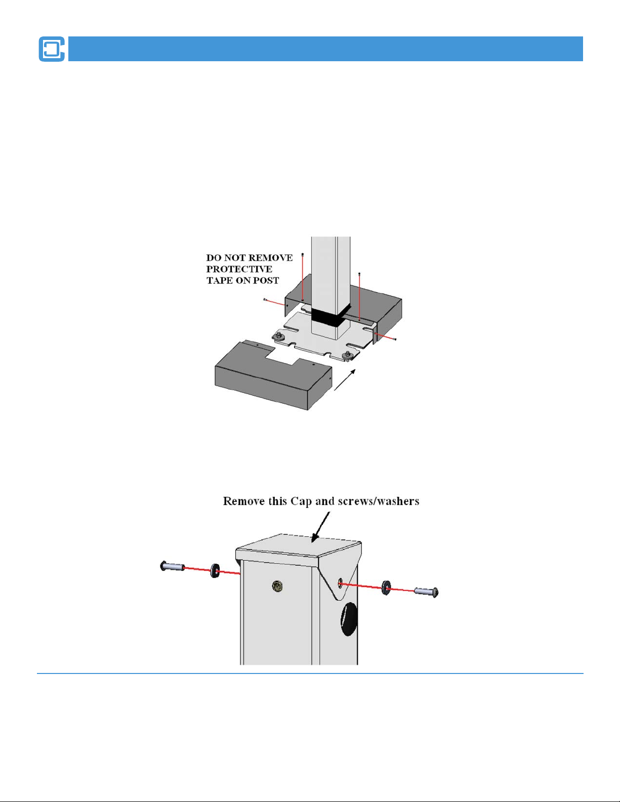
4. INSTALL THE PEDESTAL BASE COVER
A two-piece pedestal base cover set is included in the pedestal kit. The purpose of the pedestal base cover is to beautify the installation and to protect
against injury from protruding anchor bolts.
• The two covers are of an identical overlapping design.
• Slide one cover on the front side of the pedestal base until the center notch surrounds half of the pedestal post. Slide the other cover
onto the rear side in the same manner. Ensure that the anges of each cover piece are tucked inside of the opposite cover.
• Align the four screw holes of each cover piece with the corresponding screw holes on the opposite cover.
• Secure each cover piece to the other with four (4) #6-32 x 3/8” at-head tapered screws using a #2 Philips- head screwdriver.
5. REMOVE THE PEDESTAL POST CAP
A pedestal cap is provided to cover the opening to protect the conductors and inner pedestal from the elements. It may have already been assembled
on the post for protection during shipping. Temporarily remove this cap for additional access to electrical connections.
YOU HAVE NOW COMPLETED INSTALLATION OF THE MAIN PEDESTAL. PLEASE REFER TO TESLA®
WALL CONNECTOR AND/OR CLIPPERCREEK HCS INSTALLATION STEPS ACCORDING TO THE
CONFIGURATIONS DESIRED.
Page 15
ClipperCreek,Inc.
PEDESTAL INSTALLATION GUIDE: TESLA® WALL CONNECTOR
TESLA® WALL CONNECTOR INSTALLATION REQUIRES
THESE STEPS
THESE STEPS ARE TO BE COMPLETED AFTER THE MAIN PEDESTAL INSTALLATION
FOR THE TESLA® WALL CONNECTOR CONFIGURATIONS ONLY. REPEAT EACH STEP
FOR DUAL-MOUNTED CONFIGURATIONS ON THE OPPOSITE SIDE OF THE PEDESTAL:
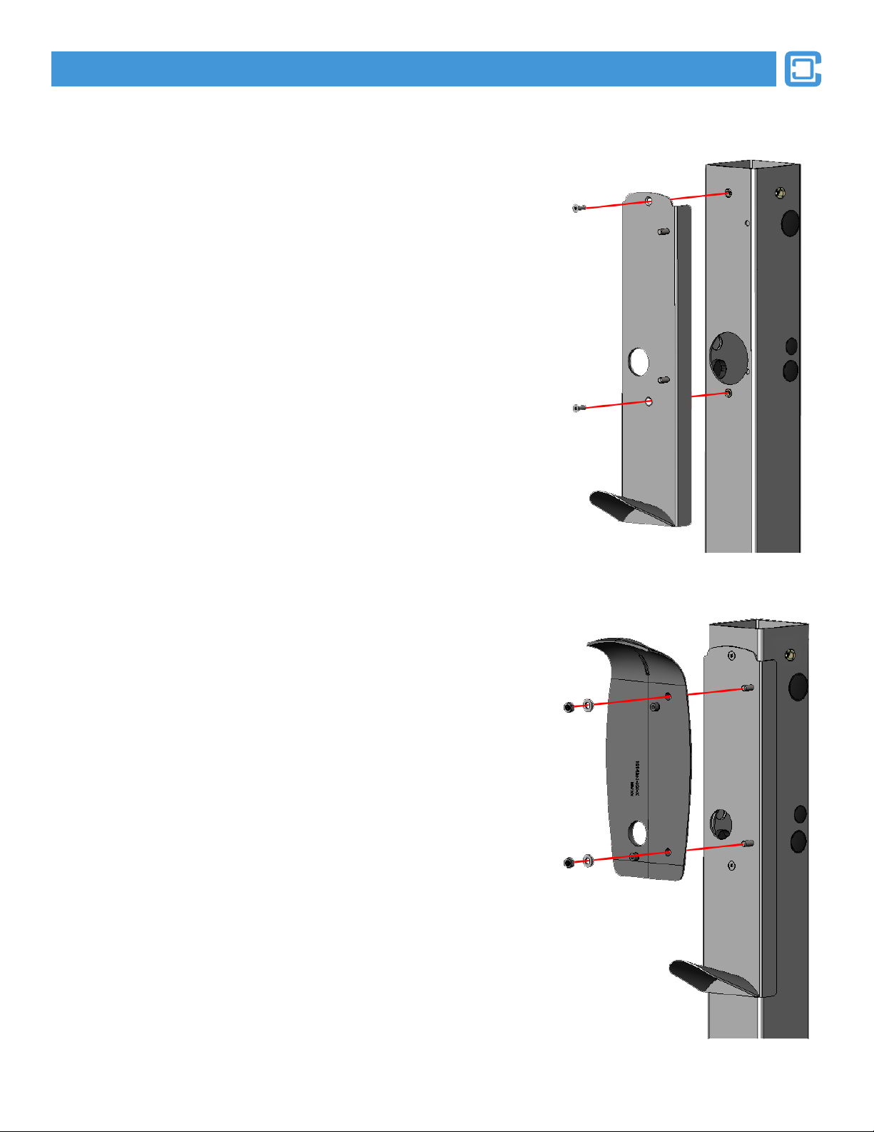
1. INSTALL THE TESLA® WALL CONNECTOR MOUNTING PLATE
A mounting plate is afxed to the front of the pedestal post to provide a at and rigid base on
which the wall connector can be mounted. In the case of a Dual-Mount installation, a second
mounting plate is afxed to the opposite side of the pedestal post.
• Hold the wall connector mounting plate against the front side of the pedestal
post as shown.
• Align the two screw holes of the mounting plate with the two corresponding
threaded inserts on the front of the pedestal post.
• To properly position the Mounting Plate use a T27 Torx driver and two (2)
1/4-20 x 3/4” Torx at-head tapered screws. Begin with the top position rst
and tighten each of the 1/4-20 x 3/4” Torx at-head tapered screws about
halfway in.
• Firmly tighten both screws until the head of the screw is ush with the
surface of the mounting plate.
• For Dual-Mount installations, repeat on the opposite side.
2. MOUNT THE TESLA® MOUNTING BRACKET TO THE MOUNTING PLATE
With the main mounting plate in place, the pedestal is now ready for the TESLA®
Mounting Bracket.
• Align the TESLA® Mounting Bracket (which is included with the TESLA®
Wall Connector) with the two studs on the Mounting Plate.
• Place one 11/16” OD stainless steel washer over each stud.
• Secure the washers and Mounting Bracket to the Mounting Plate by
rmly tightening one 5/16-18” Hex Nut onto each stud.
• For an installation with two TESLA® EVSE’s afxed to the same post,
repeat the previous steps for the opposite side.
Page 16
ClipperCreek,Inc.
PEDESTAL INSTALLATION GUIDE: TESLA® WALL CONNECTOR
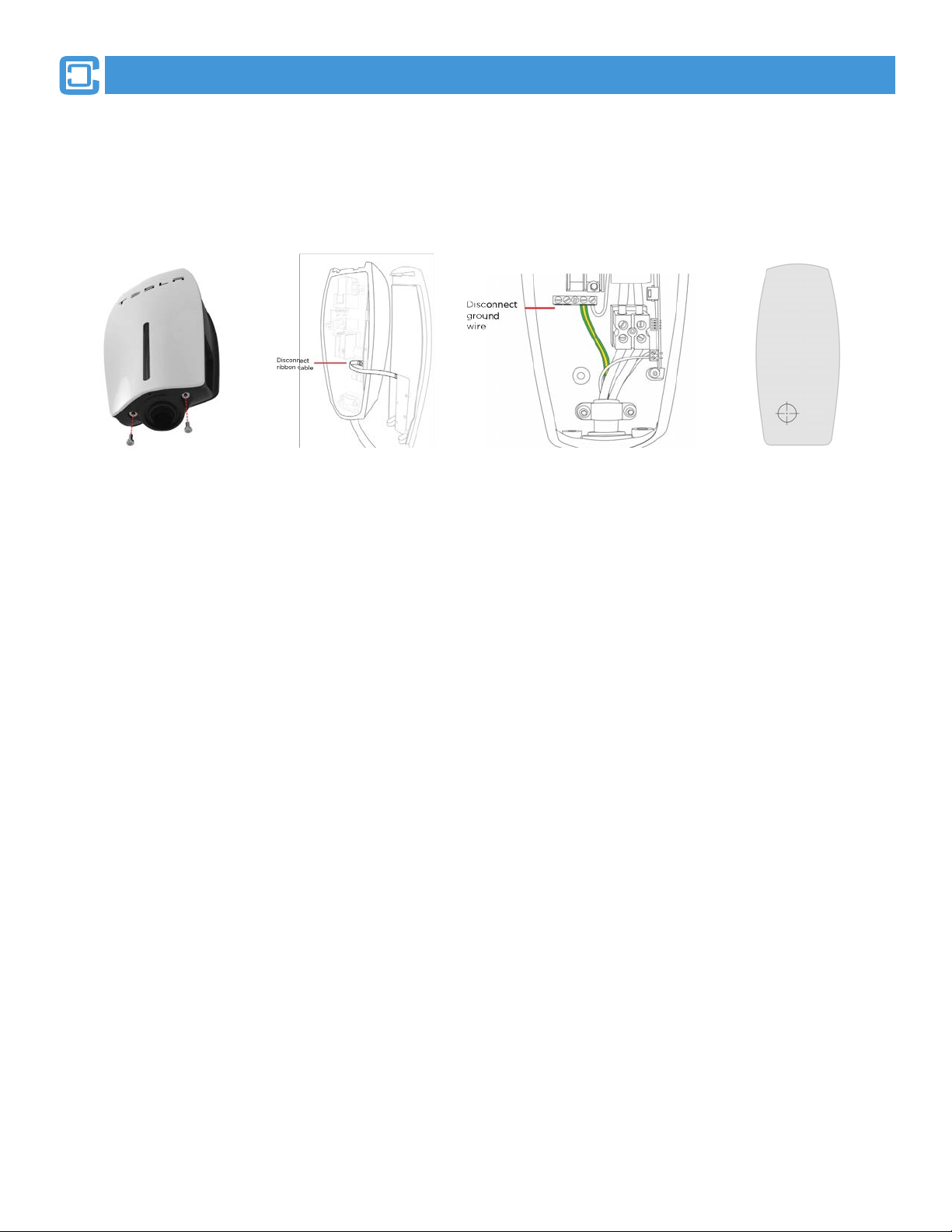
Using a Torx T20 driver,
remove the two security
screws from the bottom of
the TESLA® Wall
Connector. Keep these in
a safe place to use later.
Release the front cover
by gently pulling it
towards you.
CAUTION: The ribbon
cable may be attached.
If so, disconnect the
ribbon cable from
inside the main
enclosure to fully
release the front cover.
Do not damage the
ribbon cable.
Disconnect the ground wire
from the terminal block
and push it out of the way
to avoid damaging it when
completing the next step.
Use a 1 ¼” (32mm)
hole saw to remove
the power entry
knock-out from the
back of the
connector.
CAUTION: When
using the hole saw,
be careful not to
damage internal
components.
Reconnect the
Ground wire to the
terminal block.
3. PREPARE THE TESLA® WALL CONNECTOR FOR PEDESTAL MOUNTING
With the TESLA® Mounting Bracket in place, the pedestal is now ready for a TESLA® Wall Connector to be mounted. For Dual-Mount
Installations, repeat the steps below for the opposite side.

Page 17
ClipperCreek,Inc.
PEDESTAL INSTALLATION GUIDE: TESLA® WALL CONNECTOR
ClipperCreek,Inc.
4. MOUNT THE TESLA® WALL CONNECTOR TO THE PEDESTAL
• The TESLA® Wall Connector has provisions for 1” (25 mm) conduit.
• Align the TESLA® Wall Connector over the Mounting Bracket.
• Attach the grounding wire.
• Fasten the TESLA® Wall Connector onto the Mounting Bracket using the ange screws (supplied with the TESLA® Wall
Connector) and a ratchet wrench with 8mm socket to tighten rmly into position. Use caution to prevent pinching wires.
• For Dual-Mount Installations, repeat on the opposite side.
Page 18
ClipperCreek,Inc.
PEDESTAL INSTALLATION GUIDE: TESLA® WALL CONNECTOR
5. CONNECT THE WIRING
NOTE: For most branch circuits of 100A, use 3 AWG (26.7 mm2), 75°C (167°F)
copper wire. For installations less than 100A, use conductors that are sized according
to local electrical codes.
WARNING: Do not connect service wiring until you have read and fully understand
the pages in the document titled “Service Wiring.” If you are uncertain about the type of
power available at the service panel, consult your local utility, or contact TESLA® for
assistance.
• Turn off the Power.
WARNING: RISK OF ELECTRIC SHOCK! Before connecting the wiring, use a volt
meter to conrm that NO POWER is available at the service wiring or terminals.
• Pull the service wiring into the TESLA® Wall Connector.
• Strip wires 3/8” (10 mm)
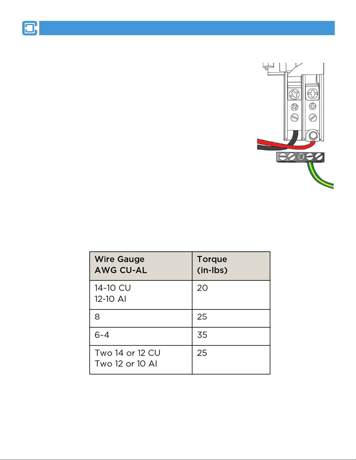
• Connect wiring to the terminal block. Connect L1 to Black, L2/N to Red, and Ground to
one of the two available Ground connectors, as shown.
NOTE: Maximum size of Ground wire is 4 AWG.
• Tighten L1 and L2 screws to 35-50 lb-in, depending on the wire gauge. Tighten Ground
screw according to the table:
• For Dual-Mount Installations, be aware that the TESLA® Wall Connector EVSE’s may
have different ratings. Extra precaustion should be taken to ensure the correct wiring
connections per EVSE.
ClipperCreek,Inc.

Page 19
ClipperCreek,Inc.
PEDESTAL INSTALLATION GUIDE: TESLA® WALL CONNECTOR
6. CONFIRM A SUCCESSFUL INSTALLATION
• Set the dip switches, located in the lower right-hand portion of the connector, to the test setting shown here. Use a pointed object such
as a pen.
• While holding the front cover near the TESLA® Wall Connector, re-connect the Ribbon Cable be aligning the cable, as shown.
• Hang the front cover over the hinge located at the top of the connector.
NOTE: Do not secure the front cover yet.
• Turn on the Power
• Hold the “RESET” button for ve seconds. This button is located on the lower right side of the TESLA® Wall Connector.
• You should now hear the contacts close and see the lights sequentially illuminate green.
• If the RED error light illuminates or ashes, refer to the troubleshooting table in the TESLA® Wall Connector Installation Guide.
• If the RED error light is not illuminated or ashing, continue with the next two steps.
• For Dual-Mount Installations, repeat on the opposite side.

Page 20
ClipperCreek,Inc.
PEDESTAL INSTALLATION GUIDE: TESLA® WALL CONNECTOR
7. SET OPERATING CURRENT
• Turn off the power.
WARNING: RISK OF ELECTRIC SHOCK! Before continuing, use a volt meter to conrm that NO POWER is available at the
service wiring or terminals.
• Open the front cover and hold it with one hand while completing the next step.
CAUTION: Do not release the front cover or allow it to hang from the ribbon cable. Doing so can damage the ribbon cable’s
connectors.
• Adjust the dip switches to set the operating current based on the type of breaker being used. Use a pointed non-conductive object
such as a plastic pen.
NOTE: Power MUST be turned off before setting or changing DIP switches. If you set DIP switches with the power on, not only is
it dangerous, because of the risk of electric shock (see warning above), but the changes are not recognized.
• Extra precaution should be used for Dual-Mount Installations. EVSE’s may look the same on the surface but have different ratings.
Set operating currents accordingly.
Table of contents
Other ClipperCreek Automobile Accessories manuals


Popular Automobile Accessories manuals by other brands

Motobilt
Motobilt MB5063 Assembly instructions

Smittybilt
Smittybilt X20 10,000LB installation instructions

Cruz
Cruz Evo Rack Alu A30-158 Assembly instructions

Inawise
Inawise TPMS-4WD series User and installation guide

Improved Racing
Improved Racing FSM -RKIT Series instructions

Vmac
Vmac VR7000 9039 installation manual


