Inawise TPMS-4WD series Manual
I
nawise
(
Australia
)
Pt
y
Ltd
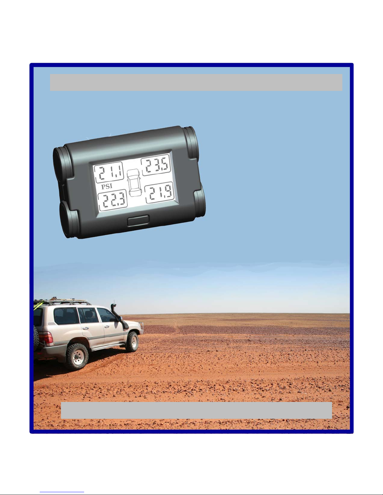
Product features and installation instructions
for the TPMS-4WD-V2tyre pressure and
temperature monitoring system.
Document Number: 913-9001 Rev G 11/July/2012
User and installation
guide
TPMS-4WD series TyrePressure
MonitoringSystem
(TPMS)

PAGE II
Pty Ltd
TPMS-4WD-V2 User and installation guide
Document 913-9001 Rev G 11/July/2012
Copyright 2009 @ll rights reserved
This document is not to be reproduced or copied in ^ny w^y unless the express permission in writing h^s been obt^ined
from
In^wise Pty Ltd
(@ustr^li^)
TABLE OF CONTENTS
INTRODUCTION..................................................................................................................................1
PRODUCT APPLICATION AND FUNCTIONALITY.....................................................................1
1. TPMS-4WD-V2 PRODUCT OVERVIEW..................................................................................1
2. PRODUCT FEATURES................................................................................................................3
2.1 FEATURES SUMMARY ................................................................................................................3
2.2 THEORY OF OPERATION .............................................................................................................4
3. INSTALLATION ...........................................................................................................................5
3.1 INSTALLING DISPLAY UNIT........................................................................................................5
3.1.1 Mounting location ............................................................................................................5
3.1.2 +12V power source determination...................................................................................6
3.1.2.1 Cigarette lighter power option: ................................................................................................... 6
3.1.2.2 Hard wired power option: ........................................................................................................... 6
3.1.3 RF Antenna.......................................................................................................................7
3.1.3.1 Wire Antenna.............................................................................................................................. 7
3.1.4 Fixing display module into place......................................................................................8
3.1.5 Reconnect vehicle battery.................................................................................................8
3.2 INSTALLING SENSOR/TRANSMITTER MODULES..........................................................................9
3.2.1 Identify the ID-Keys..........................................................................................................9
3.2.2 Sensor Disassembly........................................................................................................10
3.2.3 Loosen Electronic module..............................................................................................10
3.2.4 Fix Sensor.......................................................................................................................11
3.2.5 Adjust head angle ...........................................................................................................11
3.2.6 Torque valve stem...........................................................................................................11
3.2.7 Mount tyre ......................................................................................................................12
3.2.7.1 Lubricate................................................................................................................................... 12
3.2.7.2 Position tyre.............................................................................................................................. 12
3.2.7.3 Position upper bead................................................................................................................... 12
3.2.7.4 Finish fitting tyre....................................................................................................................... 12
3.3 SETTING PRESSURE RANGE ......................................................................................................13
3.4 CHECKING CURRENT PRESSURE RANGE ...................................................................................13
3.5 TURNING ON THE SENSOR/TRANSMITTERS ..............................................................................14
3.6 CHECKING THE SYSTEM WORKS...............................................................................................14
4. TYRE REMOVAL.......................................................................................................................15
4.1 BREAKING UPPER AND LOWER BEAD. ......................................................................................15
4.2 UPPER AND LOWER BEAD DEMOUNT........................................................................................15

PAGE III
Pty Ltd
TPMS-4WD-V2 User and installation guide
Document 913-9001 Rev G 11/July/2012
Copyright 2009 @ll rights reserved
This document is not to be reproduced or copied in ^ny w^y unless the express permission in writing h^s been obt^ined
from
In^wise Pty Ltd
(@ustr^li^)
5. OPERATING PROCEDURE......................................................................................................16
5.1 GENERAL.................................................................................................................................16
5.2 TURNING ON LCD BACKLIGHT................................................................................................16
5.3 DISPLAYING TYRE TEMPERATURE...........................................................................................17
5.4 DISPLAYING SENSOR KEY ID..................................................................................................17
5.5 DISPLAYING CURRENT PRESSURE RANGE.................................................................................17
5.6 SETTING BASE PRESSURE........................................................................................................18
5.7 ROTATING TYRES ....................................................................................................................18
5.8 DISABLING MONITORING OF SPECIFIC WHEELS ........................................................................19
5.9 REPLACING SENSORS...............................................................................................................19
5.10 SPARE TYRES ..........................................................................................................................19
6. DISPLAYS AND WARNINGS...................................................................................................20
7. TROUBLE SHOOTING..............................................................................................................22
8. QUESTIONS AND ANSWERS ..................................................................................................23
9. WARRANTY AND SUPPORT...................................................................................................27
10. TECHNICAL SPECIFICATION...........................................................................................28
............................................................28
11. SAFETY WARNING...............................................................................................................29
12. REPLACING VALVE CAPS..................................................................................................29
13. FCC COMPLIANCE...............................................................................................................29
14. DISCLAIMER..........................................................................................................................29

PAGE 1
Pty Ltd
TPMS-4WD-V2 User and installation guide
Document 913-9001 Rev G 11/July/2012
Copyright 2009 @ll rights reserved
This document is not to be reproduced or copied in ^ny w^y unless the express permission in writing h^s been obt^ined
from
In^wise Pty Ltd
(@ustr^li^)
Introduction
Product application and functionality
1. TPMS-4WD-V2 Product overview
Thank you for choosing an Inawise Tyre Monitoring product. Not only will this
product make your vehicle safer, but you are also helping the environment by
using less fuel and increasing the life of your tyres. Such is the impact that this
type of device can have, that tyre monitoring systems have been made
mandatory in the USA as of September 2007 for all new vehicles manufactured
and brought into the USA. It is speculated that many if not most other countries
will follow this lead.
This TPMS-4WD-V2 is one of a series of products in our TPMS range. This
model is specifically designed for 4WD vehicles catering to the unique
requirements imposed by 4WD applications.
One of the features of this model is a Low and High range pressure selector
switch on the back of the display module. This feature allows the system to
recalibrate to a new set of parameters with the flick of a switch, once the
vehicle’s tyres have been deflated for off road driving.
The TPMS-4WD-V2 is a realtime Tyre Pressure (and temperature) Monitoring
System (TPMS). “Realtime” meaning the actual temperature and pressure at
that moment in time. The system is designed to constantly monitor vehicle tyre
pressure and temperature whenever the display unit is powered up.
The kit consists of a display unit, 4 sensors,
a power cord, a cigarette lighter adaptor and
an integrated dual wire antenna.
Since the display unit consumes very little
power, it is recommended that the display
unit be hardwired to the vehicle’s 12V
electrical system. The 12V supply should be
live irrespective of the position of the
ignition key switch. This will enable the
TPMS-4WD-V2 to monitor the tyres not
only when the vehicle is being driven, but
also when it is parked.

PAGE 2
Pty Ltd
TPMS-4WD-V2 User and installation guide
Document 913-9001 Rev G 11/July/2012
Copyright 2009 @ll rights reserved
This document is not to be reproduced or copied in ^ny w^y unless the express permission in writing h^s been obt^ined
from
In^wise Pty Ltd
(@ustr^li^)
The TPMS-4WD-V2 is designed to monitor 4 wheels and
hence is designed for 4 wheel vehicles only. The kit is
supplied with 4 sensor assemblies which need to be fitted
to each wheel of the vehicle. Each of the sensors consists
of a valve stem, incorporating the new tyre valve and an
electronic assembly which is encapsulated within a
plastic/silicon housing.
The actual electronics within the sensor consist of a low power 433.92Mhz RF transmitter, a
microprocessor with embedded temperature and pressure transducers, a motion detector and a
lithium battery as a power source. None of the electronic components, including the lithium
battery are serviceable or replaceable. In the event of a failure the whole valve sensor assembly
can be replaced.
The sensors need to be fitted in place of the existing tyre valves. To do this the tyre needs to be
removed from the rim, the sensor fitted and then the tyre re-fitted. Normally this work is carried
out most efficiently by a specialised tyre fitter or tyre retail outlet. Only rims with a tyre valve
mounting hole of 11.3mm are supported. This is the standard size for most OEM and after
market rims.
The battery life of the sensors has been designed to last for 7 years (typical) or 250,000km of
driving. The concept being that if a set of sensors is fitted to a vehicle at the time that a new set
of tyres are fitted, the sensors will outlast the life of the tyres. As that set of tyres is replaced, it
can then be determined whether the sensors should be replaced or whether they can be utilised
for another tyre cycle.
The valve stem section of the sensor assembly is manufactured from high grade aluminium with
a propriety finish to prevent corrosion. Aluminium is utilised to ensure the sensor assembly
weight is kept to a minimum, while at the same time providing mechanical strength essential for
4WD applications. This low weight ensures that wheel balancing can be easily achieved. Under
certain environmental conditions electrolysis can occur if a steal valve cap is fitted to the valve
stem. This electrolysis will cause the valves stem to corrode. As a result it is recommended that
only the supplied plastic or an aftermarket aluminium valve cap be used.
The encapsulated electronics will ensure reliable operation even in dirty, muddy and humid off
road environments. In addition the encapsulation will also ensure the sensor can withstand
heavy vibration and shock typically encountered on rough 4wd tracks. As all the electronics are
environmentally and mechanically insulated and isolated, including the lithium battery, the unit
is not serviceable in any way, nor can the battery by replaced.
Additional sensors can be purchased and fitted to spare tyres, however only 4 wheels can be
monitored at any one time. Tyres can be easily rotated along with spare tyres due to Inawise’s
unique sensor ID technology. (See section on Tyre Rotation)

PAGE 3
Pty Ltd
TPMS-4WD-V2 User and installation guide
Document 913-9001 Rev G 11/July/2012
Copyright 2009 @ll rights reserved
This document is not to be reproduced or copied in ^ny w^y unless the express permission in writing h^s been obt^ined
from
In^wise Pty Ltd
(@ustr^li^)
2. Product Features
2.1 Features summary
Display and monitor tyre pressure and temperature of 4 wheels simultaneously
“On-Road” and “Off-Road” selector switch on back of display module
Unique patented sensor ID technology
Simple “set and forget” operation, or can be used as a performance driving aid
informing the driver of real time tyre pressures and temperatures
Reduces the risk of catastrophic tyre blowouts due to low pressure or over
temperature
Notifies driver of low tyre pressure before any noticeable affect is felt, particularly
on dirt roads and rough tracks
Audible and visual alert on over pressure
Audible and visual alert on under pressure
Audible and visual alert on fast leak detection (over 3.7 PSI within a 15second
period)
Audible and visual alert on over temperature
Display unit powered from vehicle 12V supply, no need for batteries
LCD display with white LED backlight.
Front panel “function” button to switch between pressure and temperature display.
Rear On/Off power switch
Compatible with vehicles which have tinted windows containing metallised film
Intelligent power saving technology enables battery life of sensors to last a typical
life of 7 years or 250,000km.
Sensor electronics and tyre valve all in one assembly
Electronic module located inside rim and protected from external damage
Sensor electronics encapsulated in silicon, creating environmental isolation,
ensuring long life and reliability in harsh environments.
Aluminium valve stem with proprietary protective coating to guard against
corrosion in harsh environments.
Virtually immediate driver alert when problem detected
1 year warranty.
Low power consumption.
CE/FCC/E-Mark standards certification

PAGE 4
Pty Ltd
TPMS-4WD-V2 User and installation guide
Document 913-9001 Rev G 11/July/2012
Copyright 2009 @ll rights reserved
This document is not to be reproduced or copied in ^ny w^y unless the express permission in writing h^s been obt^ined
from
In^wise Pty Ltd
(@ustr^li^)
2.2 Theory of operation
The Sensor/Transmitter modules are mounted inside each wheel rim and are held in position by a
special aluminium stem tyre valve, which replaces the existing tyre valve. The sensors monitor
the tyre pressure and transmit this information at predetermined intervals via RF (Radio
Frequency) to the display module. These transmissions occur every few seconds when the vehicle
is moving and only every few minutes when the vehicle is stationary, in order to conserve the life
of the lithium battery located within each sensor.
Whenever the display is powered up it receives this information via an RF signal. The display
module’s first step is to ascertain whether the information is from a valid sensor, and if so which
wheel it relates to. This is done via the ID-Key technology. Each sensor has a unique ID. No two
sensors have the same ID. Each sensor’s ID is associated with an “ID-Key” which is a device
which looks like a button and plugs into the side of the display module. This ensures only
information from the correct sensors is read and displayed.
The display unit, on qualifying the identity of the data from the RF signal, then evaluates the data
to ensure it is within valid parameters. The new data is displayed onto the LCD screen and if a
problem is detected the data is highlighted and an alarm is sounded.
Since tyre pressure can vary significantly due to variation in tyre temperature, it is the actual
sensor which carries out the determination of whether air is leaking from the tyre, while the
display unit determines whether the pressure is within defined limits. The microprocessors
within the sensors cross reference changes in tyre pressure with changes in tyre temperature. An
algorithm determines whether the change in tyre pressure is due to a leak or simply due to a
change in tyre temperature.
The sensor modules incorporate a motion detector to determine if the vehicle is parked or
moving. When the vehicle is parked the sensors conserve power by monitoring the tyre at greater
time interval provided the tyre is within a normal pressure range. If the vehicle is moving, or the
tyre pressure is outside a normal range, the sensors update the display every 4 seconds.
PAGE 5
Pty Ltd
TPMS-4WD-V2 User and installation guide
Document 913-9001 Rev G 11/July/2012
Copyright 2009 @ll rights reserved
This document is not to be reproduced or copied in ^ny w^y unless the express permission in writing h^s been obt^ined
from
In^wise Pty Ltd
(@ustr^li^)
3. Installation
Installation instructions for the TPMS-4WD-V2
Premise: The Display unit does not require professional installation, however it
is recommended that the Display unit be “hard wired” to the vehicles electrical
systems (rather than the 12V Cigarette lighter output), as such a general
aptitude with the ability to identify, cut, strip and join wires is required.
The sensors need to be installed in each wheel in place of the standard existing
tyre valve stem. While this can be done by a non professional, it is time
consuming and hard work without the correct equipment. In addition, on
completion the wheels need to be dynamically balanced which can only be done
with the appropriate tyre balancing equipment. Any tyre shop or corner service
station will be able to provide this service cheaply and efficiently.
3.1 Installing Display unit
3.1.1 Mounting location
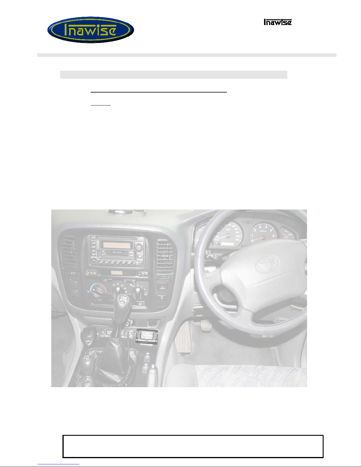
Identify a suitable location to mount the display unit. The unit should be located
in a position where the display can be easily read while driving, but not in a
location where it obscures driver view. Within a compartment in the console
(right), or on top of the dash are all suitable locations.
Once a location has been identified consider where the power cables will be
run. It may be necessary to slightly move the mounting location or find a new
location so that the power cables can be hidden or at least run where they
cannot be interfered with, or be accidentally pulled by the driver or any of the
passengers.

PAGE 6
Pty Ltd
TPMS-4WD-V2 User and installation guide
Document 913-9001 Rev G 11/July/2012
Copyright 2009 @ll rights reserved
This document is not to be reproduced or copied in ^ny w^y unless the express permission in writing h^s been obt^ined
from
In^wise Pty Ltd
(@ustr^li^)
3.1.2 +12V power source determination
At this stage you now need to determine if you intend to hard wire the 12V
power (recommended), or use the 12V Cigarette lighter adaptor. If you are
going to use the Cigarette lighter go to Step 3.1.2.1 if you are going to hard
wire the 12V supply, go to Step 3.1.2.2
3.1.2.1 Cigarette lighter power option:
With the ignition turned off, plug the cigarette adaptor cable into the power
cable connector running to the display. Locate the display module in the
approximate location you intend to mount it (but do not mount it as yet). Run
the power cable from the display unit to the cigarette lighter outlet so that it is
supported by the surrounding trims or console and if possible hidden out of
sight. If possible run the cable behind or under the dash, so as to hide it
wherever possible. Plug in the cigarette lighter connector to the cigarette lighter
output and ensure the cable is long enough and not stretched at any point. Now
proceed to Step 3.1.3
3.1.2.2 Hard wired power option:
Locate the closest and most convenient location where you can tap into the
+12V supply. Remember the supply must be permanently on even when the
ignition is turned off. Normally the vehicles stereo system uses such a supply
for the clock function. Next disconnect the vehicle’s primary lead acid battery
by removing the negative (Black) terminal from the battery.
NOTE! Many modern vehicles have stereo systems equipped with an anti theft
security feature. This feature requires a security code to be entered into the
stereo system before it can be powered up once the 12V supply is removed. If
you have such a system, ensure you have access to this security code.
Locate the display module in the approximate location you intend to mount it
(but do not mount it as yet). Next plug the hard wired power connector cable
into the socket of the power cable for the display unit and run the cable neatly,
and if possible out of view, to the location where you have identified as the
most convenient location to tap into the +12V supply. Join the red wire (+) you
have just run to the 12v source. Then join the black (-) wire to any ground
connection point. The wires can be joined using any conventional technique
such as “wire joining crimp connectors” or by cutting, stripping and soldering
the wires together. On completion ensure the wires are not exposed or shorting.
If they are exposed, use isolation tape to cover the joint. Finally use the cable
ties supplied to hold the cable firmly in place. Ensure the cable is well
supported and does not hang in any area where it can be pulled on, or caught
onto anything. Now go to Step 3.1.3
PAGE 7
Pty Ltd
TPMS-4WD-V2 User and installation guide
Document 913-9001 Rev G 11/July/2012
Copyright 2009 @ll rights reserved
This document is not to be reproduced or copied in ^ny w^y unless the express permission in writing h^s been obt^ined
from
In^wise Pty Ltd
(@ustr^li^)
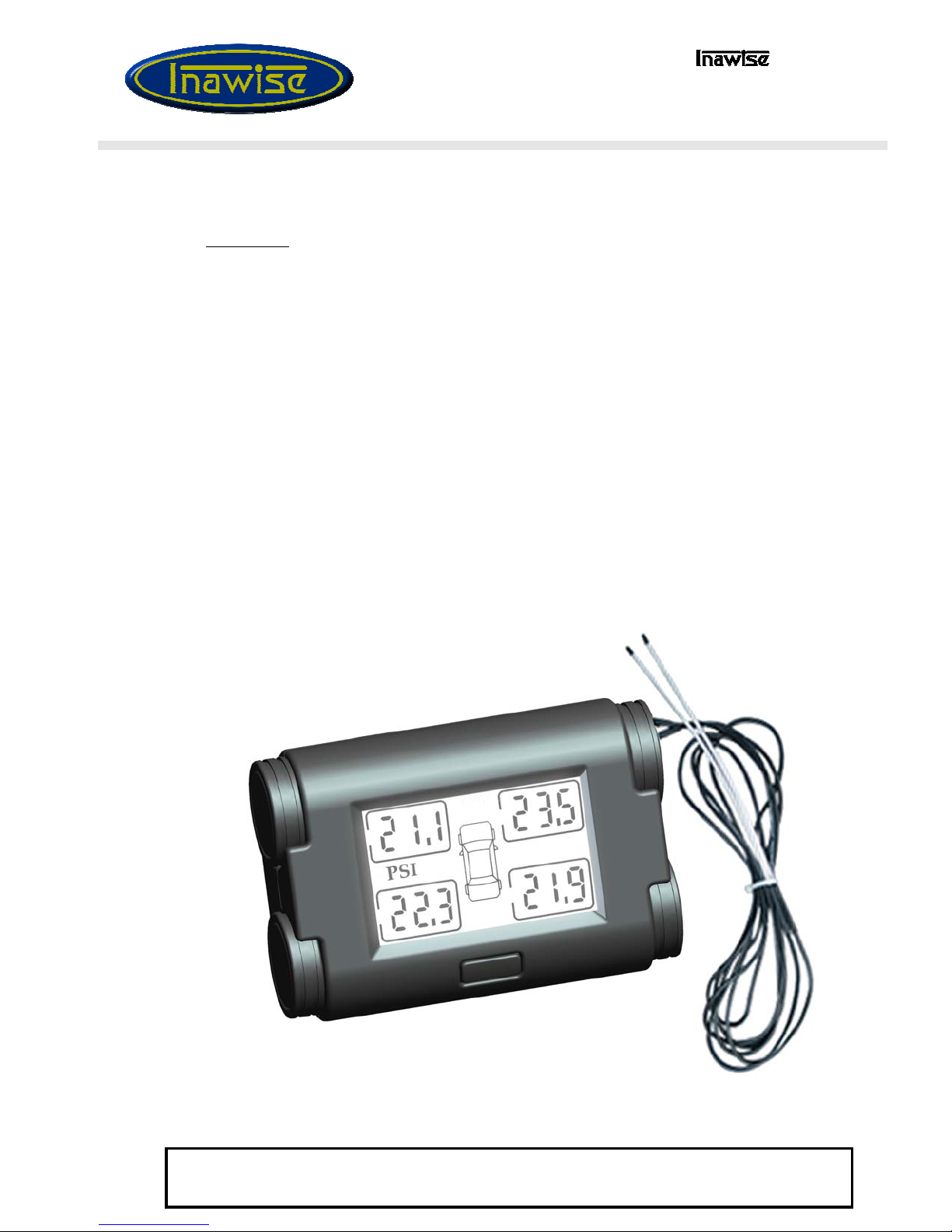
3.1.3 RF Antenna
The Antenna is used to receive the RF signal from the four individual
sensors/transmitter modules fitted to each wheel rim. The TPMS-4WD-V2 is
equipped with two long coaxial wire antennas hard wired into the display
module. These antennas need to be positioned so that a reliable level of signal
reception is obtained.
3.1.3.1 Wire Antenna
Run the two wire antennas in opposite directions across the dash (or preferably
hidden under the dash) and around the vehicle. Where ever possible hide the
wires behind trimming. Try to ensure the last 100mm end of the wire antennas
are left “Free standing” and away from other wires and metal objects. This is
the primary point where the RF signal is picked up. In absolute extreme
situations the wire antennas can be run through the fire wall, into the engine
compartment, and then run down to the bottom of the chassis where the
reception ends of the wire antenna will be located close and in direct “line of
site” to the RF transmitters mounted within the rims.
PAGE 8
Pty Ltd
TPMS-4WD-V2 User and installation guide
Document 913-9001 Rev G 11/July/2012
Copyright 2009 @ll rights reserved
This document is not to be reproduced or copied in ^ny w^y unless the express permission in writing h^s been obt^ined
from
In^wise Pty Ltd
(@ustr^li^)
3.1.4 Fixing display module into place
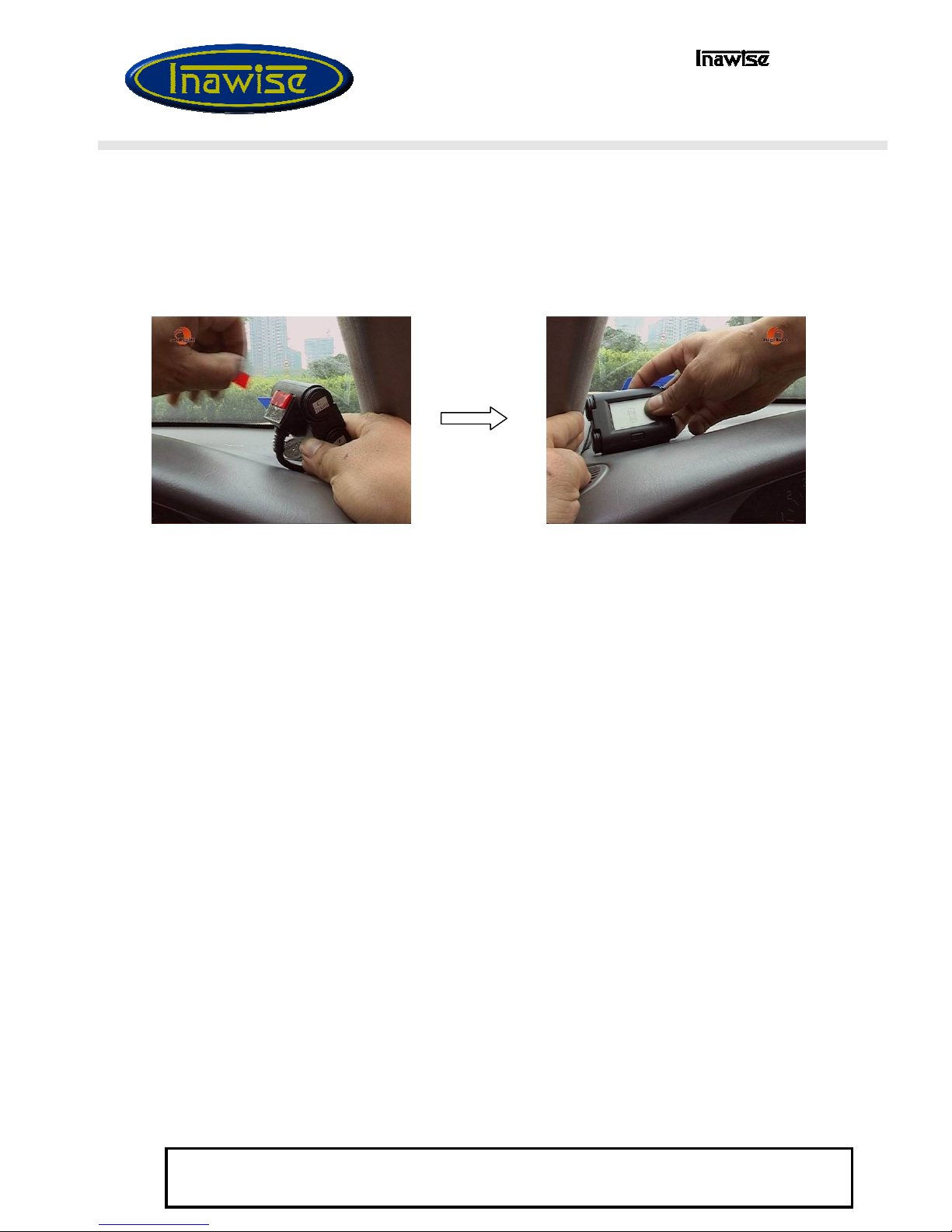
Fix the display module into place using the double sided adhesive supplied.
Ensure both surfaces are clean and if necessary clean with methylated spirits.
3.1.5 Reconnect vehicle battery
The vehicle battery can now be reconnected. The display module will power up
once the rear On/Off switch is switched to ON. As the display module powers
up, the unit will beep and all of the displays will read “000” as the sensors are
yet to be fitted to the wheels.
PAGE 9
Pty Ltd
TPMS-4WD-V2 User and installation guide
Document 913-9001 Rev G 11/July/2012
Copyright 2009 @ll rights reserved
This document is not to be reproduced or copied in ^ny w^y unless the express permission in writing h^s been obt^ined
from
In^wise Pty Ltd
(@ustr^li^)
3.2 Installing Sensor/Transmitter modules
The sensor/transmitters need to be installed to each of the 4 wheels. The modules
include a new tyre valve, meaning that the existing tyre valve needs to be removed and
discarded. In order for the sensors to be installed the wheels need to be removed from
the vehicle and the tyres then removed from the rims.
(NOTE: With some tyre/rim combinations, it is possible to fit the sensor by breaking
the tyre bead and pressing the tyre wall away from the location of the valve hole on
the rim, in order to create working clearance suitable to install the sensor module.
This method reduced the time required, as the tyre does not have to be completely
removed from the rim. Care must be taken to ensure the tyre wall does not
unexpectedly spring back into place and cause human injury. )
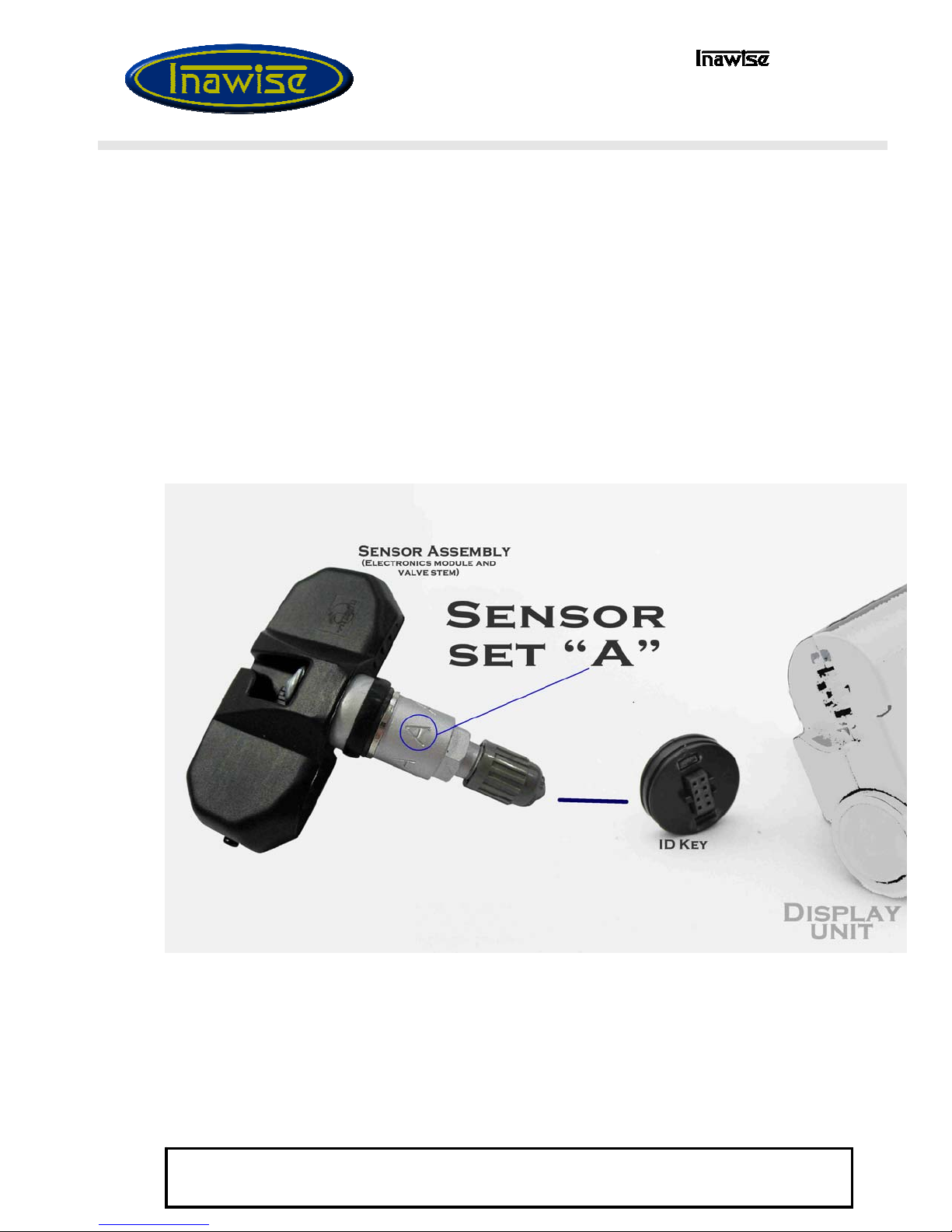
3.2.1 Identify the ID-Keys.
Each sensor is labelled with a letter “A”, “B”, “C” or “D” on its valve stem. The letters
correlate to the same letters on the identifier buttons plugged into the side or the
display module.
By default the Left Side front tyre is allocated Sensor “A”. The Right Front is sensor “B”. The Left
Back is sensor “C” and the Right Back is sensor “D”. These positions relate to the representation of
the wheel on the LCD display. The ID-Keys can be unplugged from the display module and relocated
as required. In order to unplug the ID-Keys the “release” button must first be de-pressed. This then
allows the ID-Key to be unplugged. It is recommended that the sensors be fitted in the default order to
avoid the ID-Keys requiring rotation during this initial installation.

PAGE 10
Pty Ltd
TPMS-4WD-V2 User and installation guide
Document 913-9001 Rev G 11/July/2012
Copyright 2009 @ll rights reserved
This document is not to be reproduced or copied in ^ny w^y unless the express permission in writing h^s been obt^ined
from
In^wise Pty Ltd
(@ustr^li^)
Once the ID codes for the sensor/transmitters have been identified they can be fitted to the rims.
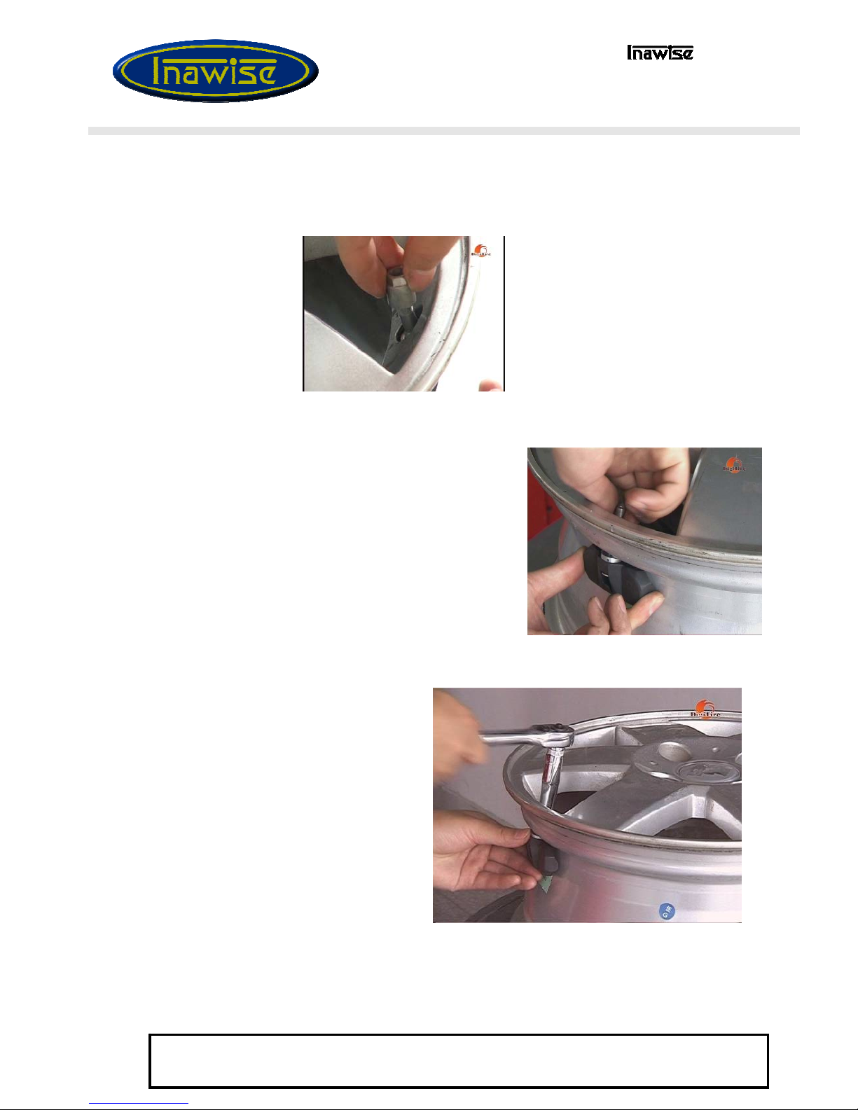
3.2.2 Sensor Disassembly
Remove the Valve Cap and the Retaining Nut
from the valve stem. The Retaining Nut has a
plastic washer pressed into its seat.
3.2.3 Loosen Electronic module
Loosen the self-locking screw to allow the Electronics module to be adjusted to
fit the rim. Clean the rim around the valve hole both on the inside and out.
Insert the valve stem through the valve hole, from the inside of the rim.
PAGE 11
Pty Ltd
TPMS-4WD-V2 User and installation guide
Document 913-9001 Rev G 11/July/2012
Copyright 2009 @ll rights reserved
This document is not to be reproduced or copied in ^ny w^y unless the express permission in writing h^s been obt^ined
from
In^wise Pty Ltd
(@ustr^li^)
3.2.4 Fix Sensor
The valve stem fixing nut incorporates a self retained plastic washer. Fit the nut to the valve stem and tighten only
by hand, ensuring the washer is in place on the nut.
3.2.5 Adjust head angle
Now adjust the angle of the electronics module so it
sits as close as possible to the rim surface,
preferably hard against it, then tighten the Self
locking screw to lock the electronics module into
that position.
3.2.6 Torque valve stem
Tighten the valve stem NUT (6)
with 3.5 to 4.6Nm (2.6 – 3.4 foot
pounds) of torque.
(Note: Correct torque setting is
critical. Under tightening will cause
air to leak. Over tightening will
cause the “valve stem air seal
rubber washer” to fail causing air
to leak. The nut can be tightened
without the use of a torque wrench.
The correct torque is reached when
the “valve stem air seal rubber
washer” is compressed to 60-70% of
its original thickness, and is not seen
to be overly bulging).
PAGE 12
Pty Ltd
TPMS-4WD-V2 User and installation guide
Document 913-9001 Rev G 11/July/2012
Copyright 2009 @ll rights reserved
This document is not to be reproduced or copied in ^ny w^y unless the express permission in writing h^s been obt^ined
from
In^wise Pty Ltd
(@ustr^li^)
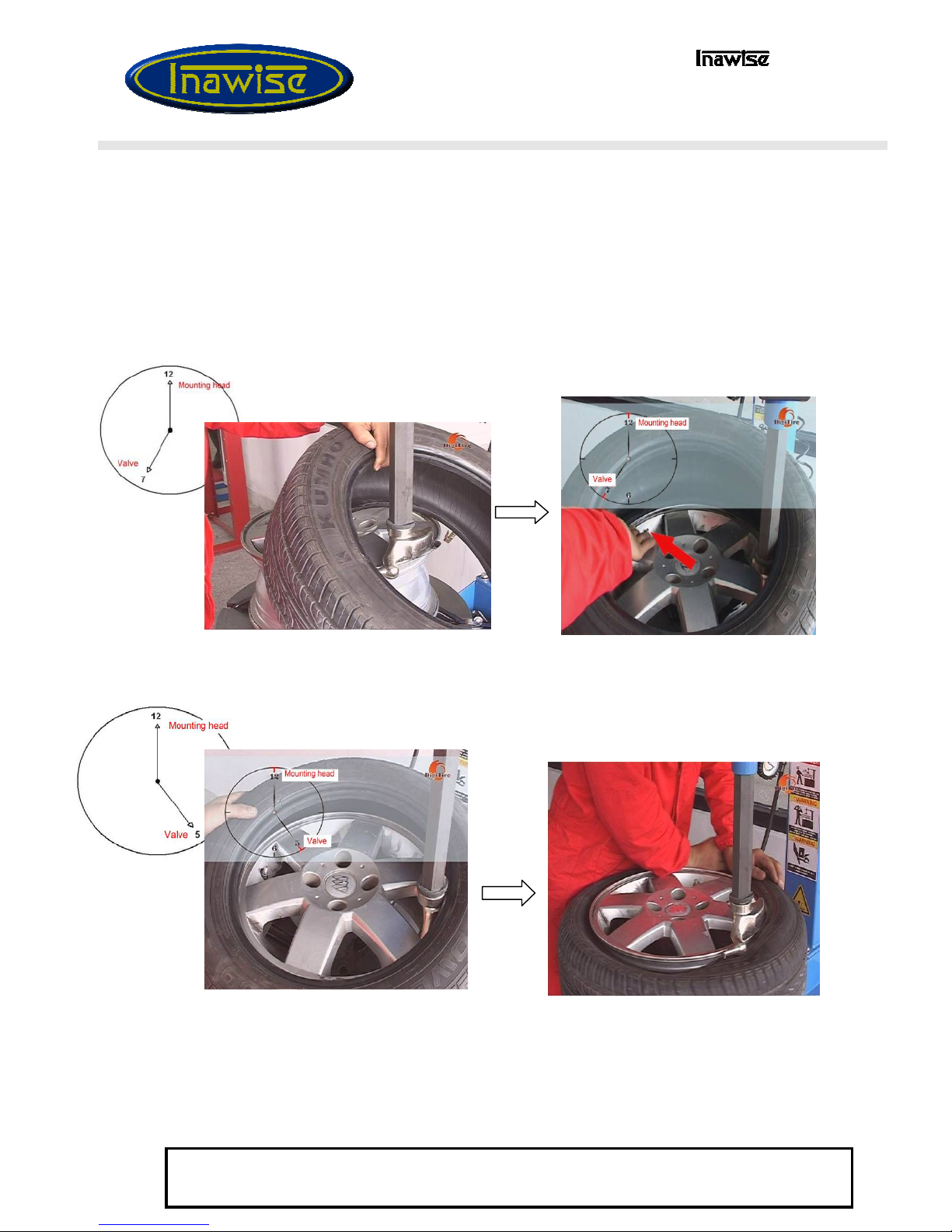
3.2.7 Mount tyre
The tyre can now been mounted back onto the rim.
3.2.7.1 Lubricate
Apply lubricant to both the tyre bead and the rim.
3.2.7.2 Position tyre
The lower bead must be mounted with the mounting head of the changer
located at 12o’clock while the position of the tyre valve is at 7 o’clock. This is
done to ensure the electronic module will not be damaged.
3.2.7.3 Position upper bead
The upper bead must be mounted with the mounting head of the tyre changer
positioned at 12 o’clock and the valve at 5 o’clock
3.2.7.4 Finish fitting tyre
The tyre can now be inflated to the vehicles recommended specified cold tyre
pressures and dynamically balanced. Repeat procedure for all other wheels and
then refit wheels to vehicle.

PAGE 13
Pty Ltd
TPMS-4WD-V2 User and installation guide
Document 913-9001 Rev G 11/July/2012
Copyright 2009 @ll rights reserved
This document is not to be reproduced or copied in ^ny w^y unless the express permission in writing h^s been obt^ined
from
In^wise Pty Ltd
(@ustr^li^)
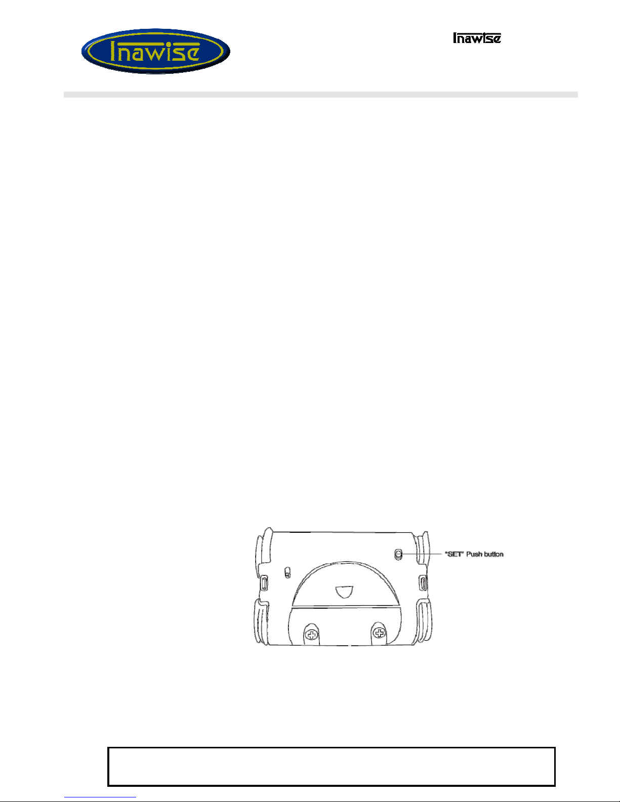
3.3 Setting pressure range
The final step is to set the pressure range for your tyres. On this model the
pressure range is set using the “Road” / “Off Road” push button switch at the
back of the display module.
Press and hold the switch for aproximatly 6 seconds to toggle betweeon “ON-
road” and “OFF-road” modes. The screen will momentarily display the word
“on” in the 4 positions to signify ON-road mode. “off” will be momentarily
displayed in the 4 positions when in OFF-road mode.
3.4 Checking current pressure range
Momentarily pressing the set button will cause the display to show the
current pressure range mode (ON-road or OFF-road) without changing
any setting.
“OFF” road mode selected
“ON” road mode selected
PAGE 14
Pty Ltd
TPMS-4WD-V2 User and installation guide
Document 913-9001 Rev G 11/July/2012
Copyright 2009 @ll rights reserved
This document is not to be reproduced or copied in ^ny w^y unless the express permission in writing h^s been obt^ined
from
In^wise Pty Ltd
(@ustr^li^)
3.5 Turning on the Sensor/Transmitters
The sensor units are shipped in a powered down sleep mode to conserve battery
life and ensure maximum battery life once they are put into service.
The sensors are activated from the “power down shipping mode” by
pressurising the sensor or driving the vehicle with the sensors installed on the
wheels at a speed of 25km/h or more for a few minutes.
As the sensors come on-line the display will change from displaying “000” to
displaying the data for that wheel.
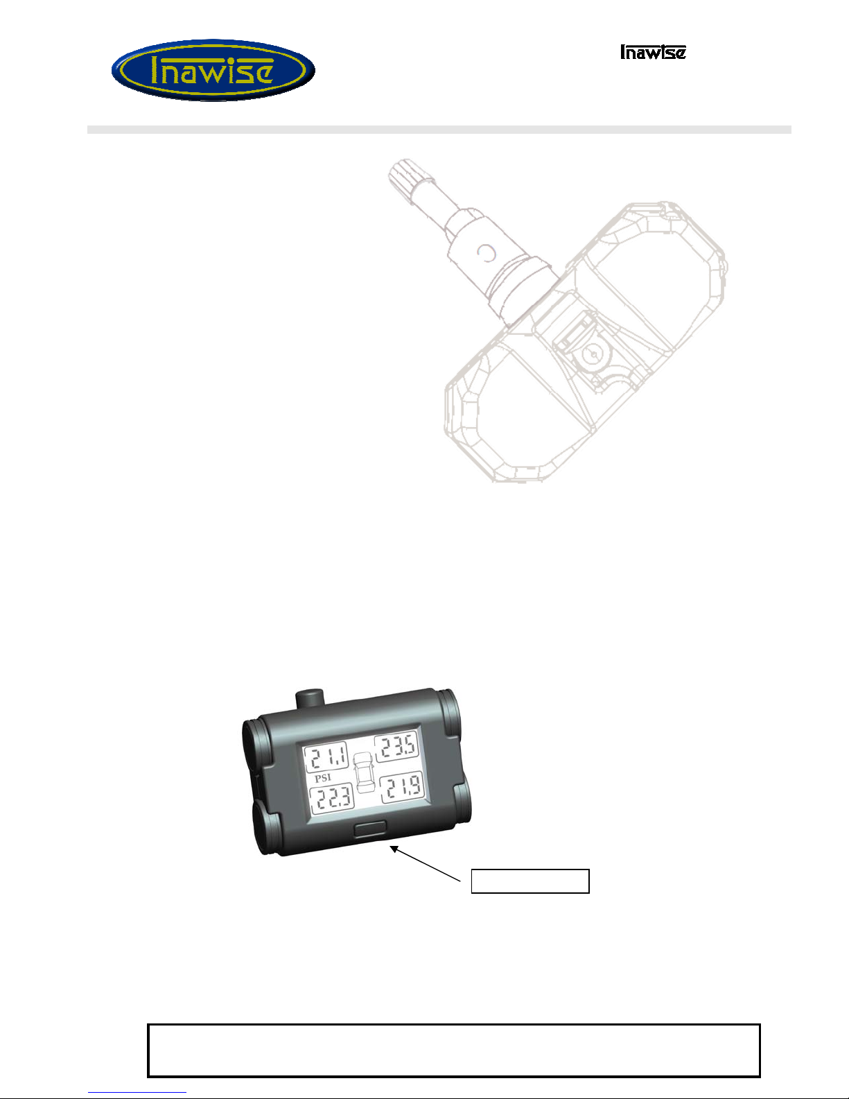
3.6 Checking the system works
The system should now be up and fully functional. All four readings on the
displays should be showing the correct tyre pressure for all four tyres.
By pressing the “function” button located at the front of the display, the display
should first turn on the LCD backlight. A second press will cause the display to
toggle from pressure display to temperature.
The LCD backlight will stay on for only a few seconds and then automatically
turn off again to preserve power.
“Function” Button

PAGE 15
Pty Ltd
TPMS-4WD-V2 User and installation guide
Document 913-9001 Rev G 11/July/2012
Copyright 2009 @ll rights reserved
This document is not to be reproduced or copied in ^ny w^y unless the express permission in writing h^s been obt^ined
from
In^wise Pty Ltd
(@ustr^li^)
4. Tyre Removal
If the rim is already fitted with a sensor/transmitter module, a specific
procedure is required to break the bead and remove the old tyre from the rim, in
order to avoid the sensor/transmitters being damaged.
4.1 Breaking upper and lower bead.
The upper and lower beads must be broken with
the bead breaker head located AT LEAST 90deg
of arc away from the tyre valve sensor /
transmitter module.
This will ensure the sensor/transmitter is not
damaged as the bead separates from the rim.
4.2 Upper and lower bead demount.
With the demounting head located at a 12.00
o’clock position, ensure the tyre valve
sensor/transmitter module is located at 11.00
o’clock. This will ensure that the sensor
/transmitter will not be damaged by the head. In
addition it is important that the sensors be located
on the opposite side to where the tyre bead is
stretched into the rim cavity.

PAGE 16
Pty Ltd
TPMS-4WD-V2 User and installation guide
Document 913-9001 Rev G 11/July/2012
Copyright 2009 @ll rights reserved
This document is not to be reproduced or copied in ^ny w^y unless the express permission in writing h^s been obt^ined
from
In^wise Pty Ltd
(@ustr^li^)
5. Operating Procedure
5.1 General
The typical operating mode of the TPMS-4WD-V2 is “set and forget”. The system will
monitor the tyres and in the event of a problem, will sound an alert, turn on the LCD
backlight and highlight the tyre with the problem.
In the event the TPMS issues an alert, as soon as it safe to do so, the driver should slow
down, turn on the hazard lights, pull over to a safe location, and investigate the problem.
During normal operating mode, the driver can at any time read the individual tyre
pressures of all 4 tyres. The location of the pressure or temperature readings on the LCD
display relates to the physical location of the tyre.
When going “Off Road”, it is simply a matter of depressing the “set” push button switch
on the back of the display and holding down for 6 seconds until you hear a beep,
indicating the pressure mode has been changed. The tyres can then be deflated to the
required pressure determined by the terrain. When going back onto a sealed road the
display module can be switched back to “Road” mode and the tyres re-inflated.
While the vehicle is parked the sensors will measure and transmit the tyre pressure and
temperature to the display unit every 4 minutes. The display will always display the
most recent reading.
Once the vehicle starts to move, the sensors measure the tyre pressure and temperature
every 4 seconds and transmit this information every 30 seconds to the display module. In
the event the sensor detects a problem, the information is transmitted immediately,
which will cause the display module to display the problem and give out an audible
alarm.
5.2 Turning on LCD Backlight
The LCD backlight can be turned on manually by pressing the function button on the
front of the display panel once.
The LCD will remain backlit for a pre-programmed period of time (around 12 seconds)
and then turn off again. The backlight cannot be manually turned off or be configured to
permanently remain on, or programmed to stay on longer.
“Function” Button
PAGE 17
Pty Ltd
TPMS-4WD-V2 User and installation guide
Document 913-9001 Rev G 11/July/2012
Copyright 2009 @ll rights reserved
This document is not to be reproduced or copied in ^ny w^y unless the express permission in writing h^s been obt^ined
from
In^wise Pty Ltd
(@ustr^li^)
5.3 Displaying Tyre Temperature
Tyre temperature can be displayed by pressing the function button twice. The
first press turns on the backlight the second press causes the display to swap to
the temperature display.
Pressing the function button again will cause it to swap back to the pressure
display.
5.4 Displaying Sensor Key ID
In addition to the labels “A”, “B”, “C” and “D” each transmitter/sensor has a
unique 6 digit identifier. Pressing and holding down the “Function” button on
the font of the display module for 8 seconds will cause the display to enter the
ID-Key display mode.
Each display will first show the first three digits of the 6 digit ID and then after
a few seconds display the last three digits.
If the display shows “---” it indicates that the ID-Key is not plugged in correctly
for that tyre or the system is faulty.
To turn off the sensor key ID display, hold the “Function” button on the front
of the display down for 8 seconds.
5.5 Displaying current pressure range
Momentarily pressing the set button at the back of the display will cause
the display to show the current pressure range mode (ON-road or OFF-
road) without changing any setting.
Table of contents


