Cloos MHW 350 SZ Guide
FÜR KÜNFTIGE VERWENDUNG AUFBEWAHREN
PLEASE KEEP SAFELY FOR FUTURE REFERENCE
A GARDER POUR FUTURE UTILISATION
MHW 350 SZ/12.00
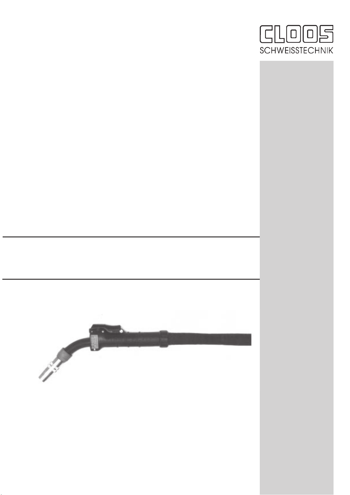
MHW 350 SZ
ERSATZTEILLISTE
SPARE PARTS LIST
LISTE DES PIECES DE RECHANGE
Leistung bei 100% ED:
350 A bei Mischgas
390 A bei CO2
Draht Ø 0,8-1,2
Ausgerüstet für Draht Ø 1,2
Power at 100 % duty cycle
350 A with mixed gas
390 A with CO2
Wire dia. 0.8 - 1.2 mm
Equipped for 1.2 mm dia.
Facteur de marche à 100 %
350 A avec gaz mixte
390 A avec CO2
Diamètre de fil 0,8 à 1,2 mm
Equipé pour diamètre 1,2 mm
CARL CLOOS
SchweißtechnikGmbH
Industriestr. • 35708 Haiger
Tel. +49 2773/85-0
Fax. +49 2773/85-275
http://www.cloos.de

Betriebsanleitung MIG/MAG-Schweißbrenner
EN 50 078
Die Hand- und Maschinenschweißbrenner dieser Produktreihe sind
ausschließlich zum Schutzgasschweißen mit inerten bzw. aktiven Gasen
universell und in allen gängigen Schweißpositionen einsetzbar.
Standardausführung ist der Hand- bzw. Maschinengriff mit Steuerein-
richtungen für max. 42V und 0,1 bis 1A. Schlauchpaketlängen von 3,4
oder 5m für Hand- sowie 1,2, 1,5, 2 und 3m für Maschinenbrenner.
Ausrüstvarianten wie z.B. Anschlüsse, Handgriffe, Verschleißteile sowie
sonstiges Zubehör entnehmen Sie bitte den aktuellen Bestellunterlagen.
Je nach Ausführung ist der MIG/MAG-Schweißbrenner gas- oder flüssig-
gekühlt.
Für die flüssiggekühlte Ausführung ist ein Kühlaggregat erforderlich.
Inbetriebnahme
Schlauchpaket ausrüsten:
Führungsspirale oder Kunststoffseele bei gerade ausgelegtem Schlauch-
paket vom Zentralanschluß (Anschlußstück) einschieben und mit dem
Spannkonus klemmen.
Brennerhals ausrüsten:
1. Gasverteiler bzw. Spritzerschutz handfest aufschrauben.
2. Stromdüse mit Steckschlüssel anziehen.
3. Gasdüse mit Drehbewegung aufstecken.
Brenner anschließen:
Der maschinenseitige Anschluß hat serienmäßig bei flüssiggekühlten
Hand- und Maschinenbrennern „SZ“, bei gasgekühlten Brennern „Z“ -
Anschluß.
Kühlmittelvorlauf anschließen:
Der blau gekennzeichnete Schlauch ist der Vorlauf und darf am Kühl-
aggregat mit dem Wasserrücklauf nicht vertauscht werden. Bei Erst-
inbetriebnahme bzw. nach jedem Schlauchpaketwechsel ist der Wasser-
umlauf zu überprüfen.
Kühlmittelrücklauf anschließen
Schutzgase:
Das Schutzgas wird in der Regel aus Stahlflaschen oder Ringleitung
entnommen und die Gasmenge am Druckminderer eingestellt. Drossel
für manuellen und maschinellen Betrieb Ø 0,6. Drossel für Roboterbetrieb
Ø 0,85.
Zum MIG/MAG-Schweißen verwendbare Schutzgase sind:
Reinargon, CO2, Gemische aus Argon und CO2 bzw. Argon, CO2und O2.
Verboten sind brennbare Gase oder Gase, die chemische Reaktionen
auslösen. Diese sind z.B.: Acetylen, Propan, reiner Wasserstoff, reiner
Sauerstoff.
Brenner mit Spannungsklasse L (bis 113V Scheitelwert)
Bedien- und Wartungshinweise
Schlauchpaket:
* Vor dem Anschließen an das Vorschubgerät kontrollieren, daß
entsprechend Drahtdurchmesser und -art die richtige Spirale oder
Seele eingesetzt ist.
* Den Drahtführungsschlauch bei jedem Drahtspulenwechsel mit
Preßluft durchblasen.
* Verschraubung auf festen Sitz überprüfen.
* Schadhafte, deformierte oder verschlissene Teile auswechseln bzw.
zur Reparatur einschicken.
Brenner:
* Ausrüstteile daraufhin kontrollieren, daß entsprechend dem Draht-
durchmesser und der Drahtart die richtige Stromdüse eingesetzt ist.
* Bei jedem Drahtwechsel darauf achten, daß der Drahtanfang gratfrei
ist.
* Den Gasdüseninnenraum von Schweißspritzern reinigen und mit
Original-Cloos-Antihaftmittel einsprühen.
* Bei flüssiggekühlten Brennerausführungen die Funktion des Kühl-
gerätes sicherstellen.
Sicherheitsmaßnahmen
Der Umgang mit dem Schweißbrenner ist gefahrlos, wenn die einschlägi-
gen Sicherheitsvorschriften beachtet und eingehalten werden z.B.:
* Die Inbetriebnahme ist nur Personen vorbehalten, die über entspre-
chende Kenntnisse im Umgang mit Lichtbogenschweißgeräten
verfügen.
* Lichtbogenschweißen kann Auge, Haut und Gehör schädigen!
Deshalb immer die vorgeschriebene Schutzkleidung, Augen- und
Gehörschutz gemäß UVV 26.0, VBG 15 tragen.
* Die angegebenen Belastungsdaten sind maximale Grenzwerte.
Überlastungen führen zwangsläufig zu Brennerzerstörung.
* Zum Verschleißteilewechsel immer die Stromquelle ausschalten.
* Die Bedienungsanleitung der einzelnen schweißtechnischen Kompo-
nenten, wie z.B. Stromquelle, Drahtvorschub- und Kühlaggregat sind
zu beachten.
* Den Brennertaster erst dann bestätigen, wenn alle Voraussetzungen
zum gefahrlosen Schweißen erfüllt sind.
* Schlauchpaket niemals über scharfe Kanten ziehen, im Spritzer-
bereich oder auf heißen Werkstücken ablegen.
* Unbeteiligte Personen durch Vorhänge und Schutzwände gegen
optische Strahlung und Blendegefahr schützen.
* Die Handhabung von Gasflaschen ist den Anweisungen der Gaseher-
steller und der Druckgasverordnung zu entnehmen.
* Werkstücke, die mit chlorierten Lösungsmittel entfettet wurden,
müssen vor dem Schweißen mit klarem Wasser abgespritzt werden
sonst besteht die Gefahr der Phosgengasbildung. Aus dem gleichen
Grund dürfen keine chlorhaltigen Entfettungsbäder in der Nähe des
Schweißplatzes aufgestellt sein.
* Alle Metalldämpfe sind schädlich! Es wird besonders vor Blei, Nickel,
Chrom, Cadminum, Kupfer, Zink und Beryllium gewarnt. Durch
Belüftung oder Absaugung ist gegebenenfalls dafür zu sorgen, daß die
MAK-Werte nicht überschritten werden (MAK = Maximale Arbeitsplatz-
konzentration gesundheitsschädlicher Arbeitsstoffe).
* Beobachten Sie die Schweißstelle und die Umgebung auch nach
Beendigung der Schweißung. Brände können durch Schwelung auch
noch später entstehen.
Gewährleistung
Dieser MIG/MAG-Schweißbrenner ist ein Original Cloos-Erzeugnis. Die
Cloos Schweißtechnik GmbH garantiert eine fehlerfreie Herstellung und
übernimmt für diesen Schweißbrenner bei Auslieferung eine werkseitige
Fertigungs- und Funktionsgarantie entsprechend dem Stand der Technik
und der geltenden Vorschriften. Gewährleistungen können nur für
Fertigungsmängel, nicht aber für Schäden, die auf natürliche Abnutzung,
Überlastung oder unsachgemäße Behandlung zurückzuführen sind,
gegeben werden. Verschleißteile fallen generell nicht unter die Gewähr-
leistung. Jeder Schweißbrenner darf nur mit Original-Cloos-Ersatzteilen
betrieben werden.
Störungsursache
Störung Mögliche Ursachen
Kein Lichtbogen - Stromzuleitung zu Werkstück oder Brenner unterbrochen
- Stromquelle oder Steuerung defekt
- Steuerleitung unterbrochen
- Schaltschutz in der Stromquelle wird nicht aktiviert
Lichtbogen zwischen Gasdüse und Werkstück - Brückenbildung im Gasdüseninnenraum durch Schweißspritzer
Brennerkörper oder Stromzuleitung überhitzt - Kühlmitteldurchfluß nicht ausreichend
- Schweißstrom zu hoch
- Kühlmittelschlauch oder flüssiggekühltes Stromkabel verengt oder
verschlossen
- Stromdüse nicht richtig angezogen
Schweißdraht mit Stromdüse verschmolzen - Drahtvorschub setzt zu spät ein
- Draht blockiert im Drahtführungsschlauch infolge starker Verschmutzung
oder zu starker Krümmung
- Vorschubgeschwindigkeit zu niedrig
- Stromdüsenabstand zum Werkstück zu groß/ zu klein
Unregelmäßiger Drahtvorschub - Anpreßkraft der Andruckrolle zu gering
- Störungen im Drahtführungsschlauch
- Falsche Führungsspirale oder -seele
- Störungen in der Steuerung
- Zu stark abgenutzte oder falsch gewählte Vorschubrollen

Operating instructions for MIG/MAG welding torches
EN 50 078
The manual and machine welding torches in this product series are
exclusively suitable for use with inert or active gases, universally and in
all common welding positions.
The standard design comprises: handle with controlling devices for max.
42 V and 0.1 to 1 A, cable assembly lengths of 3 m, 4 m or 5 m for
manual torches and 1.2 , 1.5 , 2 and 3 m for machine torches.
Please see the current order documents (sales documents) for various
fittings such as connections, handles, wear parts and other accessories.
MIG/MAG welding torches may be gas-cooled or water-cooled.
Water-cooled torches require a cooling radiator.
Commissioning
Prepare cable assembly:
The guide liner or plastic liner is pushed through the straight cable
assembly from the central connection (connection piece) and is clamped
with the clamping cone.
Prepare torch neck:
1. Manually screw on the gas distributor or spatter protection.
2. Use a spanner to tighten the current tip.
3. Fasten the gas shroud with a rotary motion (movement).
Connect torch:
The standard connection on the machine side is a „SZ“ connection for
water-cooled manual and machine torches and a „Z“ connection for gas-
cooled torches.
Connect cooling liquid advance:
The water advance hose is marked blue and must not be mixed up with
the water return hose on the cooler. The water circulation must be
checked during the first commissioning and after each change of the
cable assembly.
Connect cooling liquid return.
Shielding gases:
The shielding gas is taken from steel bottles or a closed circular pipeline.
The gas quantity is set on the pressure reducing valve. Choke diameter
for manual and automatic operation is 0.6 and for robot operation 0.85.
The following gases are used for MIG/MAG welding:
Pure Argon, CO2, mixtures of Argon and CO2or Argon, CO2and O2.
Flammable gases or gases which induce a chemical reaction, such as
Acetylene, Propane, pure Hydrogen, pure Oxygen are prohibited.
Torch of the voltage class L (up to a peak value of 113V)
Operating and maintenance instructions
Cable assembly:
* Prior to connection to the wire feed unit make sure that the correct
liner is used in accordance to the wire type and diameter.
* Compressed air should always be blown through the wire guide hose
when the wire coil has been exchanged.
* Make sure that the screwed connections are correctly tightened.
* Damaged, deformed or worn parts have to be exchanged or returned
for repair.
Torch:
* Make sure that the correct current tip is used with regard to the wire
diameter and type of wire.
* When changing the wire coil it is important that the wire beginning
is without burr.
* Remove the weld spatters from the interior of the gas shroud and
spray with original Cloos torch spray.
* When water-cooled torches are used the function of the cooler
must be guaranteed.
Safety precautions
The use of the welding torches is safe when the common safety
regulations are kept:
* Commissioning is reserved to qualified persons who are familiar with
the use of arc welding machines.
* Arc welding may be harmful for eyes, skin and ears ! Protective
clothing, eye and ear protection according to UVV 26.0, VBG 15 rules
should be worn.
* The given load data are maximum limit values. Overload will
inevitably damage the torch.
* The power source must always be switched off when wear parts
are exchanged.
* The operating instructions for the individual welding components
such as power source, wire feed unit and cooler must be
adhered to.
* The torch trigger should only be pressed when all conditions for
a safe welding are fulfilled.
* Never pull the cable assembly over feather edges or deposit it within
the range of spatters or on hot workpieces.
* Protect other persons by curtains and protective walls against optical
rays and the danger of glare.
* The instructions of the gas manufacturers and the high-pressure gas
rules are important for handling the gas bottles (cyliders).
* Workpieces which have been degreased with a chlorinated solvent
must be washed down with clear water before welding to avoid the
danger of phosgen gas formation. For the same reason chloric
degreasing bathes are not allowed in the proximity of the welding
location.
* All metal vapours are toxic! Be careful with lead, nickle, chrome,
cadmium, copper, zinc, berillium. If necessary a ventilation or
aspiration must be used to avoid that the MAK values are exceeded
(MAK „ maximum concentration of harmful working materials on the
work place).
* Please observe the weld area and its surroundings when welding
has finished. Fire may break out later due to smoldering.
Warranty
This MIG/MAG welding torch is an original Cloos product. Cloos
Schweißtechnik GmbH guarantee for a faultless production and function
according to the state of art and the existing provisions. Guarantee can
only be claimed for defective material but not for damages due to normal
wear, overload or inexpert handling. There is no warranty against wear
parts. Original Cloos spare parts must be used only for each welding
torch.
Problems during operation
Faults Possible causes
No arc - Current supply to the workpiece or torch is interrupted
- Faulty power source or control
- Control lead interrupted
- Switching protection in the power source is not activated
Arc between gas shroud and workpiece - Bridge formation inside the gas shroud due to weld spatters
Overheated torch body or supply lead - Insufficient flow of cooling liquid
- Welding current too high
- Cooling liquid hose or water-cooled current cable too narrow or
closed
- Current tip is not correctly tightened
Welding wire melted with current tip - Wire feed starts too late
- Wire is jammed in the wire guide hose due to severe contamination
or too strong bending
- Wire feed speed is too low
- Current tip distance to the workpiece is too large/too small
Irregular wire feed - Too low pressure of pinch roller
- Faults in the wire guide hose
- Wrong guide liner or liner (core)
- Problems in the control
- Wrong wire feed rollers or rollers too severely worn

Instructions d’opération pour torches de soudage
MIG/MAG - EN 50 078
Les torches de soudage manuelles et machine dans cette série sont
exclusivement destinées au soudage sous atmosphère protectrice avec
des gaz inertes ou actifs, universellement et dans toutes les positions de
soudage.
L’exécution standard comprend la poignée avec unités de commande
pour max. 42V et 0,1 jusqu’à 1A. Longueurs disponibles du faisceau de
câbles de 3m, 4m ou 5m pour torche manuelle et 1.2 , 1.5 , 2 et 3 m pour
torche machine.
D’autres accessoires comme p. ex. des raccords, poignées, pièces
d’usure etc. se trouvent dans la documentation de vente actuelle.
La torche de soudage MIG/MAG peut être refroidie par gaz ou par eau.
Les modèles refroidis par eau nécessitent un réfrigérant.
Mise en service
Préparer le faisceau de câbles:
Pousser la spirale guide-fil ou spirale en plastique à travers le raccord
central (pièce de raccordement) dans le faisceau de câbles aligné (droit)
et serrer par le cône de serrage.
Préparer l’extrémité de la torche:
1. Visser le distributeur gaz ou la protection contre les projections de
soudage.
2. Serrer la buse courant à l’aide d’une clé.
3. Tourner la tuyère gaz en position.
Raccorder la torche:
En standard, les torches manuelles et machine, refroidies par eau, sont
pourvues d’un raccord „SZ“ au côté machine et les torches refroidies par
gaz d’un raccord „Z“.
Raccorder le tuyau d’arrivée d’eau:
Le tuyau d’arrivée d’eau est marqué en bleu et ne doit pas être inversé
avec le tuyau de retour d’eau sur le réfrigérant. Il faut vérifier la circulation
d’eau à la première mise en service et après tout échange du faisceau de
câbles. Brancher le tuyau de retour d’eau
Les gaz protecteurs:
Le gaz protecteur est fourni en bouteilles acier à gaz ou d’une canalisa-
tion de gaz. La quantité de gaz est réglée sur le débitmètre. Le diamètre
de sortie pour opération manuelle et automatique est Ø 0,6, pour
opération robotique 0,85.
N’utiliser que des gaz protecteurs convenables au soudage MIG/MAG
comme Argon, CO2, un mélange d’Argon et CO2 ou Argon, CO2et O2.
Des gaz inflammables ou des gaz qui déclenchent une réaction chimique
comme par exemple l’ Acetylène, le Propane, l’Hydrogène pur, l’Oxygène
pur etc. sont interdits.
Torches de la classe tension L (jusqu’à une valeur de crête de 113V).
Instructions d’opération et de maintenance
Faisceaux de câbles:
* Avant le raccordement au dévidoir de fil il faut assurer que la spirale
utilisée correspond au diamètre et type de fil.
* Après le changement d’une bobine fil il faut nettoyer le tuyau guide fil
par soufflage à l’air comprimé.
* Vérifier que les raccords sont correctement vissés.
* Il faut échanger ou renvoyer pour réparation les pièces défectueuses,
déformées ou usées.
Torche:
* Il faut vérifier que la buse de courant est celle en rapport
au diamètre du fil et le tye du fil.
* A chaque changement de la bobione de fil il est important que
l’extrémité du fil soit sans bavure.
* Enlever les projections de soudage à l’intérieur de la tuyère gaz et
appliquer le spray anti-adhérent original Cloos.
* Pour l’utilisation de torches refroidies par eau il faut s’assurer du
bon fonctionnement du réfrigérant.
Mesures de précaution
Le maniement de la torche de soudage est sans danger si les prescrip-
tions de sécurité correspondantes sont respectées et tenues, comme par
exemple:
* La mise en service est réservée au personnel qualifié en ce qui
concerne le maniement de postes de soudage sous atmosphère
protectrice.
* Le soudage à l’arc peut porter préjudice aux yeux, à la peau et aux
oreilles. Il faut toujours porter des vêtements protecteurs, une protection
des yeux et une protection acoustique suivant les instructions UVV 26.0,
VBG 15.
* Les données indiquées de charge sont des valeurs de limite maximum.
Une surcharge conduit inévitablement à une destruction de la torche.
* Il faut toujours mettre hors circuit la source de courant pour échanger
des pièces d’usure.
* Il est important de lire les manuels d’opération pour les composants
individuels comme p. ex. la source de courant, le dévidoir de fil et le
réfrigérant.
* N’appuyer la gachette qu’après toutes les conditions requises au
soudage sûre ont été remplies.
* Ne jamais tirer le faisceau de câbles sur des des arêtes vives ou
déposer dans la zone des protections ou sur la pièce chaude.
* Protéger les autres personnes contre les rayons ou le danger
d’éblouissement au moyen d’une parois de séparation ou de rideaux.
* En ce qui concerne le maniement de bouteilles de gaz il faut respecter
les instructions du fabricant de gaz et les prescriptions pour le gaz
comprimé.
* Pièces qui ont été dégraissées par des agents chlorés doivent être
nettoyées à l’eau fraîche avant le soudage pour éviter le développe-ment
du gaz phogène. Pour la même raison des bains de dégraissage chlorés
sont interdits dans le voisinage de l’endroit de soudage.
* Toutes les fumées de métal sont toxiques! Attention au alliages
contenant du plomb, du nickel, du chrome, du cadmium, du cuivre, du
zinc et du béryllium. Une amenée suffisante d’air frais ou un système
d’aspiration de fumée sont important pour ne pas dépasser les
valeurs MAK (MAK = concentration maximum de matières nuisibles
à la santé sur le lieu de travail).
* Observer la soudure et l’environnement également après avoir terminé
le soudage. Il est possible que des feux se déclarent plus
tard à cause d’une combustion incomplète.
Garantie
Cette torche de soudage MIG/MAG est un produit original Cloos. La
Cloos Schweißtechnik GmbH donne une garantie contre les défauts et
une garantie de fabrication et de fonctionnement à la livraison de cette
torche de soudge selon les règles de l’art et les règlements en
vigueur. Les défauts à cause d’une usure normale, de surcharge ou d’un
maniement incorrect ne sont pas couverts par la garantie. Les pièces
d’usure ne sont pas sous garantie. N’utiliser que des pièces
de rechange originale Cloos.
Problèmes de fonctionnement
Defaut Causes possibles
Pas de l’arc. - L’amenée courant à la pièce ou à la torche est interrompue
- Source de courant ou commande défectueuse
- Ligne de commande interrompue (coupée)
- Protection de couplage dans la source de courant n’est pas active
Arc entre la tuyère gaz et la pièce - Ponts dans l’intérieur de la tuyère gaz à cause de projections de
soudage
Corps de la torche ou ligne courant surchauffé - Circulation insuffisante du liquide de refroidissement
- Courant de soudage trop élevé
- Tuyau de refroidissement d’eau ou câble de courant refroidi par eau
rétréci ou bouché
- Buse de courant n’est pas serrée correctement
Fil de soudage fondu ensemble avec la buse de courant - L’avance fil démarre trop tard
- Fil bouché dans le tuyau guide fil suite à une sevère pollution ou
une forte courbure
- Vitesse d’avance trop faible
- Distance entre la buse de courant et la pièce trop grande / trop petite
Avance du fil irrégulière - Pression des galets-presseur trop faible.
- Défauts dans le tuyau guide fil
- Mauvaise spirale guide-fil ou spirale intérieure
- Défaut dans la commande
- Galets d’entraînement de fil trop fortement usés ou incorrects
MHW 350 SZ - SZ Anschluß / SZ connection / raccord SZ
Geräteseite (DV) /machine side Brennerseite/torch side
côté de la machine côté de la torche
MHW 350 SZ
48
42
48.1
48.3
48.4
48.2
34.1
34
36
35
33
32
31
41
39
43
37 46
47
40
35
34.2
34

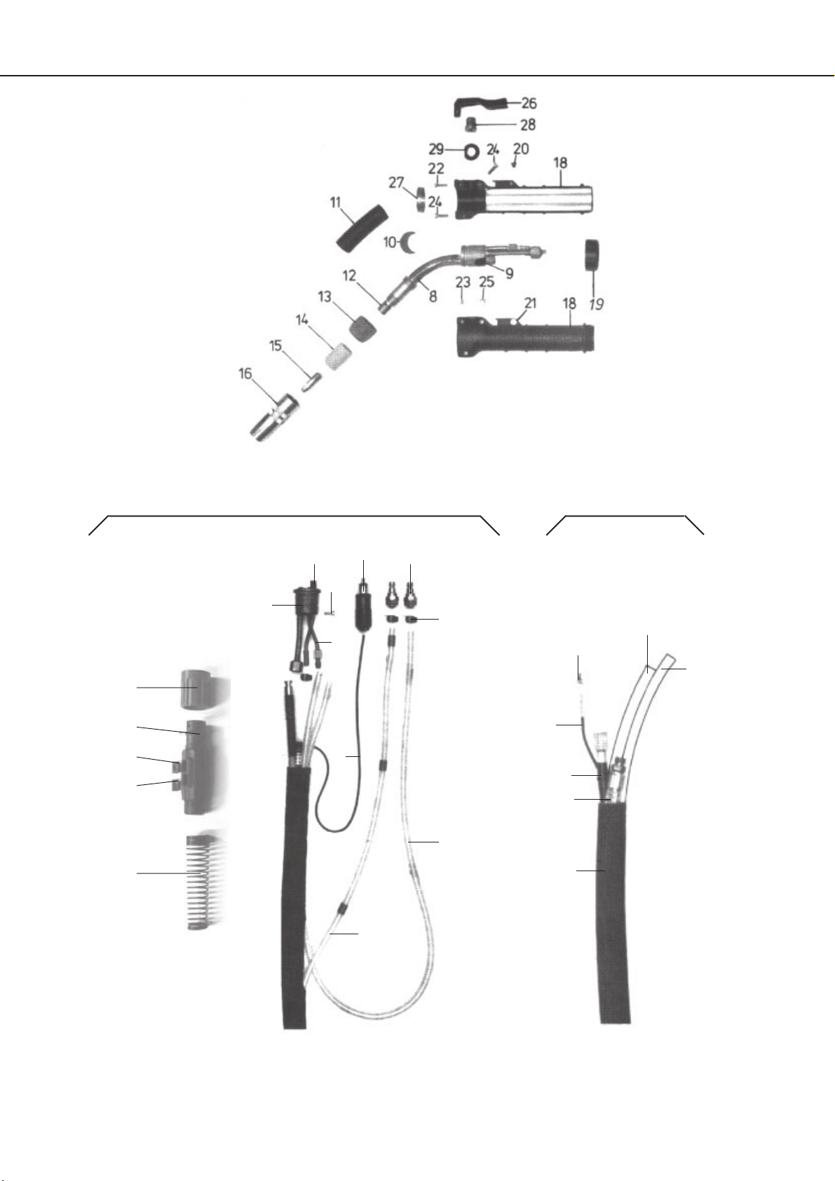
Ersatzteilliste für MHW 350 SZ
Spare parts list for MHW 350 SZ
Liste des pièces de rechange pour MHW 350 SZ
Pos. Bestell-Nr./Ref.-No./ Bezeichnung / Description / Désignation
Référence
MHW 350 SZ
1 558 25 04 00 Schweißbrenner kpl. mit 3 m Schlauchpaket / welding torch compl. with 3 m
cable assembly / torche de soudage cpl. avec faisceau de câbles de 3 m
558 25 05 00 Schweißbrenner kpl. mit 4 m Schlauchpaket / welding torch compl. with 4 m
cable assembly / torche de soudage cpl. avec faisceau de câbles de 4 m
558 25 06 00 Schweißbrenner kpl. mit 5 m Schlauchpaket / welding torch compl. with 5 m
cable assembly / torche de soudage cpl. avec faisceau de câbles de 5 m
558 55 14 00 Schlauchpaket kpl. 3m lang / cable assembly compl. 3m / faisceau de cables
cpl. 3m
558 55 15 00 Schlauchpaket kpl. 4m lang / cable assembly compl. 4m / faisceau de cables
cpl. 4m
558 55 16 00 Schlauchpaket kpl. 5m lang / cable assembly compl. 5m / faisceau de cables
cpl. 5m
8 558 20 01 01 Brennerinnenkörper mit Gewinde am Wassermantel /torch interior body with
thread at the water cooling jacket / corps intérieur de torche avec filet à la
chemise d'eau
9 524 01 05 01 Isolierbuchse (eingeklebt) / sticked-in insulation bush / douille isolante collée
10 558 00 02 03 Isolierscheibe / insulation disk / disque isolante
11 558 00 02 02 Schutzschlauch / protective hose / tuyau protecteur
12 558 20 01 08 Düsenstock / nozzle base / embout de buse
13 558 00 02 07 Isolierspannbuchse mit Rechtsgewinde / insulating clamping bush with right
hand thread / douille de serrage isolante avec filet à droite
14 558 00 02 13 Isolierhülse mit Linksgewinde / insulating bush with left hand thread / douille
isolante avec filet à gauche
15 062 02 00 02 Stromdüse M 8 für Draht-Ø 0,8 / current tip M 8, for wire Ø 0.8 / buse de courant
M 8 pour fil Ø 0,8
062 02 00 03 dto. 1,0
062 02 00 04 dto. 1,2
16 065 00 82 00 Gasdüse NW Ø 17 / gas nozzle NW Ø 17 / tuyère gaz NW Ø 17
Schweißbrennergriff / Welding torch handle / Poignée de la torche de
soudage
18 524 01 06 01 Griffschalen (Paar) mit Stanniol / handles (pair) with tin foil / poignée (paire)
avec feuille d'étain
19 524 01 03 10 Schraubkappe / screw cap / bouchon fileté
20 100 40 40 05 Senkkopfschraube M 4 x 5 DIN 963 / countersunk head screw M 4 x 5 DIN 963/
vis à tête noyée M 4 x 5 DIN 963
21 524 01 06 03 Haltescheibe M 4 x 2,2 / holding disk M 4 x 2.2 / rondelle d'arrêt M 4 x 2,2
22 100 20 30 14 Zylinderschraube M 3 x 14 DIN 84 / cylinder screw M 3 x 14 DIN 84 / vis
cylindrique M 3 x 14 DIN 84
23 103 60 30 00 Hutmutter M 3 DIN 1587 / cap nut M 3 DIN 1587 / écrou à chapeau M 3
DIN 1587
24 100 20 40 14 Zylinderschraube M 4 x 14 DIN 84 / cylinder screw M 4 x 14 DIN 84 / vis
cylindrique M 4 x 14 DIN 84
25 103 60 40 00 Hutmutter M 4 DIN 1587 / cap nut M 4 DIN 1587 / écrou à chapeau M 4
DIN 1587
26 061 01 05 07 Schalterhebel / switch lever / levier de commande
27 524 01 03 02 Kontaktring / contact ring / bague de contact
28 061 01 05 00 Brennerschalter / torch switch / gachette
29 061 01 05 06 Isolierring / insulation ring / bague isolante
31 040 06 04 23 Schutzschlauch für Schlauchpaket 3 m / protective hose for cable assembly 3 m/
tuyau de protection pour faisceau de câbles de 3 m
040 06 04 24 dto., 4 m
040 06 04 25 dto., 5 m
32 558 50 14 02 Strom-Wasserkabel kpl. 3 m / current-water cable compl. 3 m / câble d’eau et
de courant cpl. 3 m
558 50 15 02 dto., 4 m

Ersatzteilliste für MHW 350 SZ
Spare parts list for MHW 350 SZ
Liste des pièces de rechange pour MHW 350 SZ
Pos. Bestell-Nr./Ref.-No./ Bezeichnung / Description / Désignation
Référence
MHW 350 SZ
558 50 16 02 dto., 5 m
33 041 01 04 44 Drahtförderschlauch kpl. 3 m / wire guide hose compl. 3 m / gaine guide fil cpl.
3 m
041 01 04 45 dto., 4 m
041 01 04 46 dto., 5 m
34 040 01 01 00 Wasservorlaufschlauch p/m / water reverse hose p/m / tuyau de retour d’eau p/m
34.1 040 01 01 00 Gasschlauch / gas hose / tuyau de gaz
34.2 040 01 01 00 Wasserrücklaufschlauch p/m / water reverse hose p/m / tuyau de retour d’eau p/m
35 038 07 13 00 Steuerleitung 1-pol. p/m / control lead 1 pol. p/m / câble d’alimentation 1 pôles p/m
36 524 01 05 10 Kontakteinheit / contact unit / unité de contact
37 010 03 02 00 Stecker 1-pol. / plug 1 pol. / fiche 1 pôle
39 604 01 04 01 Dichtring (O-Ring) / O-ring / bague d’étanchéité (bague O)
40 604 04 05 00 Anschlußstück / connection piece / pièce de raccordement
41 102 50 50 06 Feststellschraube M 5 x 6 DIN 915 / locking screw M 5 x 6 DIN 915 / vis d'arret
M 5 x 6 DIN 915
42 604 02 02 00 Überwurfmutter / union nut / écrou isolé
43 100 20 40 10 Zylinderschraube M 4 x 10 DIN 84 / cylinder screw M 4 x 10 DIN 84 / vis
cylindrique M 4 x 10 DIN 84
46 032 03 00 70 Stecknippel / plug-in nipple / raccord fileté enfichable
47 042 02 00 11 Einohrklemme / eor clamp / serrage d'oreille
48 605 02 20 00 Knickschutz bestehend aus:crack protection consisting of:
protection de flambage composée de:
48.1 605 02 16 00 Zweiteiliger Knickschutz/ two-piece crack protection /
protection à deux pièces
48.2 605 02 16 01 Knickschutzfedern/ crack protection springs / ressorts pour protection
48.3 605 02 16 05 Verschlußkappe mit Bohrung/ cap with bore / capuchon avec alésage
48.4 605 02 16 04 Verschlußkappe mit Doppelbohrung / cap with double bore /
capuchon avec alésage double

Pos. Bestell-Nr./Ref.-No./ Bezeichnung / Description / Désignation
Référence
Innenspiralen für Stahldrähte / Stahlrunddraht ,verzinkt
Liners for steel wires / round wires, galvanized /
Spirales intérieures pour fil acier / fil rond, galvanisé/
Innenspirale für Drähte 0,8 - 1,0 mm ( 1,8 x 4 ) / liner for wire
0,8 - 1,0 mm / spirale intérieur pour fil 0,8 - 1,2 mm
041 02 06 04 Länge 3 m / length 3 m / longueur 3 m
041 02 06 05 Länge 4 m / length 4 m / longueur 4 m
041 02 06 06 Länge 5 m / length 5 m / longueur 5 m
041 02 06 00 Meterware 50 m Rolle / yard ware, 50 m roll /
matériel au mètre, rouleau à 50 m
Innenspirale für Draht 1,2 mm ( 2,1 x 4,5 ) / liner for wire 1,2 mm /
spirale intérieur pour fil 1,2 mm
041 02 01 04 Länge 3 m / length 3 m / longueur 3 m
041 02 01 05 Länge 4 m / length 4 m / longueur 4 m
041 02 01 06 Länge 5 m / length 5 m / longueur 5 m
041 02 01 00 Meterware 50 m Rolle / yard ware, 50 m roll /
matériel au mètre, rouleau à 50 m
Innenspirale für Aluminium - u. CrNi Drähte
PTFE mit 15 % Graphit schwarz Meterware
Liner for aluminium and CrNi wires - PTFE with 15 % graphit,
Spirale intérieure pour fils aluminium et CrNi - PTFE avec 15 %
black - yard ware / noir - matériel au mètre
040 08 11 00 Innenspirale für Draht 0,8 mm ( 1,5 x 4,0 ) / liner for wire 0,8 mm /
spirale intérieure pour fil 0,8 mm
040 08 10 00 Innenspirale für Draht 1,0 u. 1,2 mm ( 2,0 x 4,0 ) / liner for wire
1,0 and 1,2 mm / spirale intérieure pour fil 1,0 et 1,0 mm
Integrierte Spiralklemmung im SZ Anschluß zum Schweißen
erforderlich ! ! Integrated spiral clamp in SZ connection required for
welding !! Borne hélicoidale intégrée dans raccord SZ est utile pour
le soudage !!
604 02 22 00 Spannschraube / clamping screw / vis de serrage
604 02 23 00 Spanneinsatz für alle Spiralen / clamping insert for all liners /
pièce de serrage pour toutes les spirales
Ersatzteilliste für MHW 350 SZ
Spare parts list for MHW 350 SZ
Liste des pièces de rechange pour MHW 350 SZ
MHW 350 SZ
Table of contents
Other Cloos Welding Accessories manuals


