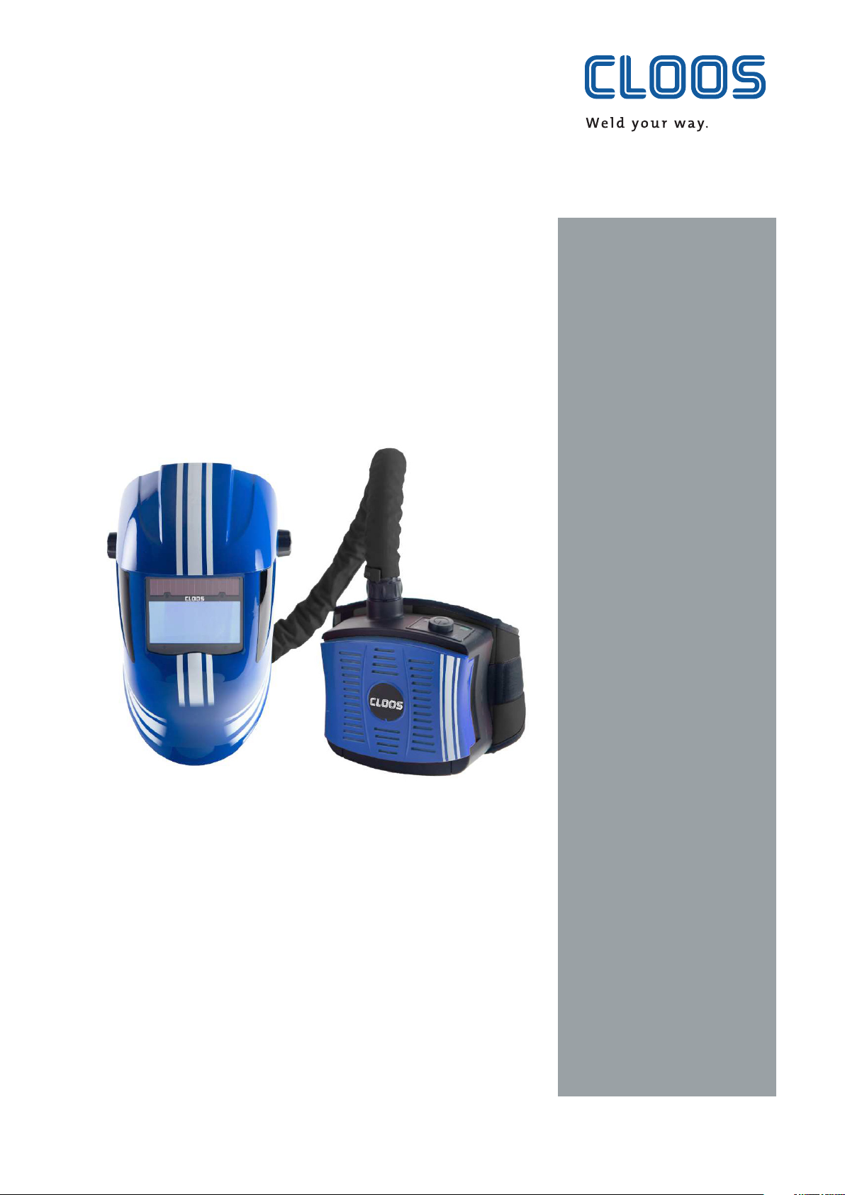
Cloos Arc Flash 4 evo Guide
Operating
instructions
and
spare parts list
Welding accessories
CLOOS Arc Flash 4 evo Air
Rev.0
Original instructions

2
Important:
This manual must be read and fully understood before using the CLOOS ArcFlash4air unit.
The manual must be retained for future reference.
Compulsory Information for the use of a powered respirator with Hood type head unit
Please read these instructions carefully before unpacking your product. Failure to comply with the instructions in
this leaflet may void your warranty and adversely affect your health. If you have any questions regarding the suita-
bility of this product to your task, please contact an occupational hygienist or call the manufacturers technical
help line.
Address and telephone number information is printed at the back off this leaflet.
CLOOS ArcFlash4air has been designed and manufactured to comply with EN12941: 1998 as a TH2P R SL device.
8S4275 (Guide to implementing an effective respiratory protective device program), which the user is advised to
read, defines an EN12941 TH2P R SL device as offering an Assigned Protection Factor of 20.
CLOOS ArcFlash4air can only provide this level of protection when used with filters provided by the manufacturer
marked "CLOOS ArcFlash4" and "EN12941:1998 TH2P R SL".
The CR-2B01/2013 is certified with the PL-2B01/2013 and GT-2B01/2013 helmets which are certified to EN 175 B.
CLOOS ArcFlash4air is manufactured under ISO 9001:2000 Quality System.
Certification EN 12941:1998+A1:2003+A2:2008 Certified by: DEKRA-EXAM GmbH

3
Inhalt
1. General information.................................................................................4
1.1 Operating instructions..........................................................................................4
1.2 Explanation of symbols.........................................................................................4
1.3 Limitation of liability..............................................................................................5
1.4 Copyright .....................................................................................................................5
2. Safety ...........................................................................................................6
2.1 Proper use....................................................................................................................6
2.2 Reasonably foreseeable misuse.........................................................................6
2.3 Personnel requirements........................................................................................6
2.4 Hazards.........................................................................................................................6
2.5 Warranty clause........................................................................................................7
2.6 Warranty ......................................................................................................................8
3. Technical Data............................................................................................9
3.1 Storage and Transportation ................................................................................9
4. Unpacking / Assembly............................................................................10
4.1 Unpacking ................................................................................................................10
4.2 Assembly...................................................................................................................10
4.2.1 Waist-Belt Adjustment...................................................................................10
4.2.2 Particulate Filter ................................................................................................10
4.2.3 Removing the Filter..........................................................................................11
4.2.4 Fitting a new Filter ...........................................................................................11
4.2.5 Changing the Pre-Filter..................................................................................11
4.2.6 Attaching the Hose to the Blower Unit...................................................11
4.2.7 Donning the Welding Helmet .....................................................................11
5. Before use .................................................................................................12
5.1 Inspection before use..........................................................................................12
5.2 Air Flow Test.............................................................................................................12
5.3 Batteries ....................................................................................................................12
5.3.1 Battery charging................................................................................................13
5.3.2 Battery changing...............................................................................................13
6. Usage .........................................................................................................14
7. Maintenance / Cleaning ........................................................................15
8. Fault finding.............................................................................................16
9. List of parts...............................................................................................17
4
1. General information
1.1 Operating instructions
These operating instructions contain important information for the safe,
efficient handling of the device. Compliance with all of the safety instruc-
tions and operating instructions contained herein is a pre-condition for
safe working with the device.
Illustrations in these instructions are intended to provide a basic under-
standing, and may differ from the actual design of the device. Claims
cannot be derived therefrom.
Information manual for the welder protective helmet complying with Para-
graph 1.4 of Appendix ll of the EC regulations. The welding helmet is a high
quality product that contribute to the comfort and safety of the welder.
The welding helmet may be used only in connection with arc welding.
1.2 Explanation of symbols
Warning and safety instructions in the manual are identified by means of
pictograms and highlighted in a colour-coded block.
Warning and safety instructions which draw your attention to basic haz-
ards are additionally marked with signal words which express the level of
damage. These are categorised as follows:
The signal word indicates a hazard with a high level of risk, which, if not
avoided, leads to fatal or severe injury.
The signal word indicates a hazard with a moderate level of risk, which, if
not avoided, can lead to fatal or severe injury.
The signal word indicates a hazard with a low level of risk, which, if not
avoided, leads to minor or moderate injury.
The signal word indicates a hazard without risk of a physical impairment,
which, if not avoided, can lead to property damage.
Tips and recommendations as well as information for efficient and
smooth operation.
DANGER!
WARNING!
CAUTION!
ATTENTION!
NOTICE

5
1.3 Limitation of liability
All information and notes in this manual were compiled taking into con-
sideration the applicable standards and regulations and the state of the
art, as well as our many years of knowledge and experience .
The manufacturer assumes no liability for damages caused by:
• Non-observanceofthemanual
• Improperuse
• Useofuntrainedandnon-instructedpersonnel
• Unauthorisedalterations
• Technicalchanges
• Useofunauthorisedspareparts
1.4 Copyright
This document is protected by copyright.
The unauthorised transfer of these instructions to third parties, reproduc-
tion of any kind and in any form, even in excerpts, as well as the recovery
and/or notification of the content is prohibited without the written per-
mission of the publisher.
Infringements of this trademark will be subject to compensation for dam-
ages. All rights to further claims reserved.

6
2. Safety
2.1 Proper use
The device is only to be used for the following purpose:
The device affords reliable protection against particulates and aerosols
Risk from improper use!
Any use of the device other than the intended purpose can lead to hazard-
ous situations.
• Thedeviceshouldnormallyonlybeusedinaccordancewiththeinfor-
mationinthisdocument,inparticularwithrespecttocompliancewith
theapplicationlimitvaluesgiveninthetechnicalspecifications.
• Refrainfromanyuseofthedevicewhichdiffersorextendsbeyond
theselimits.
• Donotconvert,retrofitorotherwisealterthestructureorindividual
fittedcomponentswiththeaimofalteringthescopeofapplicationor
usabilityofthedevice.
Claims of any kind for damages caused by improper use are excluded.
2.2 Reasonably foreseeable misuse
The unit must not be used in an atmosphere that is immediately hazar-
dous to user hygiene or health and or has oxygen content of less than 17 %
or contains unknown substances.
• in confined spaces or unventilated areas such as tanks, pipes, canals etc.,
• near to flames and or sparks,
• in areas with danger of explosion,
• in an area where there are high winds
2.3 Personnel requirements
Work may only be performed by a trained specialist. All personnel involved
must be instructed with regard to the safety requirements, safety regula-
tions and operational instructions which must be applied in their work.
2.4 Hazards
The warning and safety notices listed here and in the operations chapters
of these instructions must be observed in order to prevent potential harm
to health and hazardous situations.
Hazard by lack of oxygen (<17 %)
When the blower unit is switched off a rapid buildup of carbon dioxide and
depletion of oxygen within the head unit may occur
• Itisessentialnottousetheblowerunitwhenitisswitchedoff.
WARNING!
WARNING!

7
Choking hazard
The user is advised to leave the contaminated area immediately if:
• TheManufacturer‘sMinimumDesignFlow(MMDF)warningAlarm
sounds.
• breathingbecomesdifficult,
• dizzinessordistressoccurs,
• anypartofthesystembecomesdamaged,
• airflowintotheHead-Unitdecreasesorstops,
• contaminantcanbesmeltortastedinsidetheHead-Unit,
• Materialsthatmaycomeintocontactwiththeusersskinarenot
knowntocauseallergiereactionstothemajorityofindividualsbutin
theunlikelyeventofareaction,theusershouldimmediatelyleavethe
contaminatedarea,removetheunitandseekmedicaladvice.
2.5 Warranty clause
If any of these conditions are not kept or followed, the warranty is automa-
tically invalid.
Nothing is allowed to touch the moving parts.
There is no attempt to modify or alter the unit or filter in any way. No wa-
ter or other Iiquids enter the unit in any way - in particular the motor and
fan, the filter or the battery.
Make sure that the headpiece fits the user‘s face perfectly. Only then the
efficiency of the system is sufficient. The protective factor of the complete
system is reduced if the seal of the headpiece is not fitted properly, for e.g.
due to beards or long hair intervening into the seal line.
There is a possibility that the hose to the head unit may become caught up
in use. The blower unit should be positioned on the person in such a way
as to reduce this possibility.
Filters cannot be fitted directly to the head units and should not be adap-
ted to do so. Correct respiratory protection will not be provided if any parts
of the equipment are modified. At very high work rates the pressure in the
device may become negative at peak inhalation flow. Blower unit systems
are for use only by competent, trained personnel.
Filters should not be modified to fit different blower units.
WARNING!

8
2.6 Warranty
The blower unit is guaranteed for a period of 12 months from date of
purchase against mechanical or electrical defects.
The battery is guaranteed for a period of 6 months from the date of
purchase.
This guarantee is subject to:
• The blower unit has been used solely for the purpose for which it is
intended.
• The blower unit has not been subject to misuse, accident, modification
or repair.
In the event of a claim, contact the retailer from which the blower unit
was purchased. This guarantee does not cover normal wear and tear. This
guarantee does not affect your legal rights.

9
3. Technical Data
Air flow 180…220 Litres/min
Minimum 170 Litres/min
Weight with filter 920 g
Head size 535…600 mm
Type of filter P R S L
Type of battery Replaceable and rechargeable Li-Ion 7.4 V/5200 mAh
Charging cycles >350
Visual, audible alarm for low battery voltage
Visual, audible alarms for insufficient flow rate (below 170Umin)
Actual Protection Factor (APF) 20
Noise level 65 dBA
Operating time On minimum flow rate with a new filter and fully
charged battery in a clean environment:
• greater than 8 hours
• 5 hours on maximum flow rate
Operatingtimecanbeshortenedincaseofclogged
filterunderchargedbattery.
Filter Symbols:
R = means the filter is reusable for more than one shift.
S = means the filter protects against solid particles.
L =means the filter proteet against Iiquid particies.
3.1 Storage and Transportation
When not in use or during transportation the blower and head units
should be stored in the container in which they were provided, or other
similar container, such that it is out of direct sunlight, not in contact with
solvents and cannot be damaged by physical contact with hard suriaces/
items.
Do not store:
• outside the temperature range of +O°C to +40°C or
• humidity above 75%RH

10
4. Unpacking / Assembly
4.1 Unpacking
Check that the package is complete and that no part is damaged due to
the transport or for other reasons.
A package with the complete system including accessories contains:
1. Blower unit incl. Battery and P R SL Filter and Pre Filter
2. Belt
3. Air hose
4. Air flow indicator
5. Battery charger
6. User Instructions
4.2 Assembly
Attach the respiratory unit onto the belt: Pass the inner strap through
the back of the blower loops. The pass through the 2 belt loops and then
through the buckle. Fit the battery to the Blower unit.
4.2.1 Waist-Belt Adjustment
Put the belt around your waist with the blower unit to the back and fasten
the two ends together. If the belt is too loose, slide the male adjuster down
the belt, towards the female half. If the belt is too tight, slide the male ad-
juster away from the female half.
Repeat the above processes until a comfortable and secure fit is achieved.
Once the belt fits correctly, secure any excess belt material using the velcro
sections.
4.2.2 Particulate Filter
Use only filters and Pre-Filters as supplied by CLOOS. It should first be
ascertained by consulting an occupational hygienist or by calling the ma-
nufacturers technical help line as to whether or not the CLOOS Filter will
offer suitable protection from the hazard.
The respiratory power unit is equipped with a high efficiency particle
filter class PRSL and a Pre-Filter. As soon as the warning alarm sounds, the
Pre-FiIter should be exchanged or checked. In very dusty areas this can be
necessary on a frequent basis.
The filters must be regularly checked (see „Air Flow Test“) and replaced.
Make sure that the new filters are within their expiry date, unused and
not evidently damaged . From the hygienic point of view the maximum
working time of a main filter is 180 hours and should not be exceeded. It is
prohibited to clean the filters by any procedure!
11
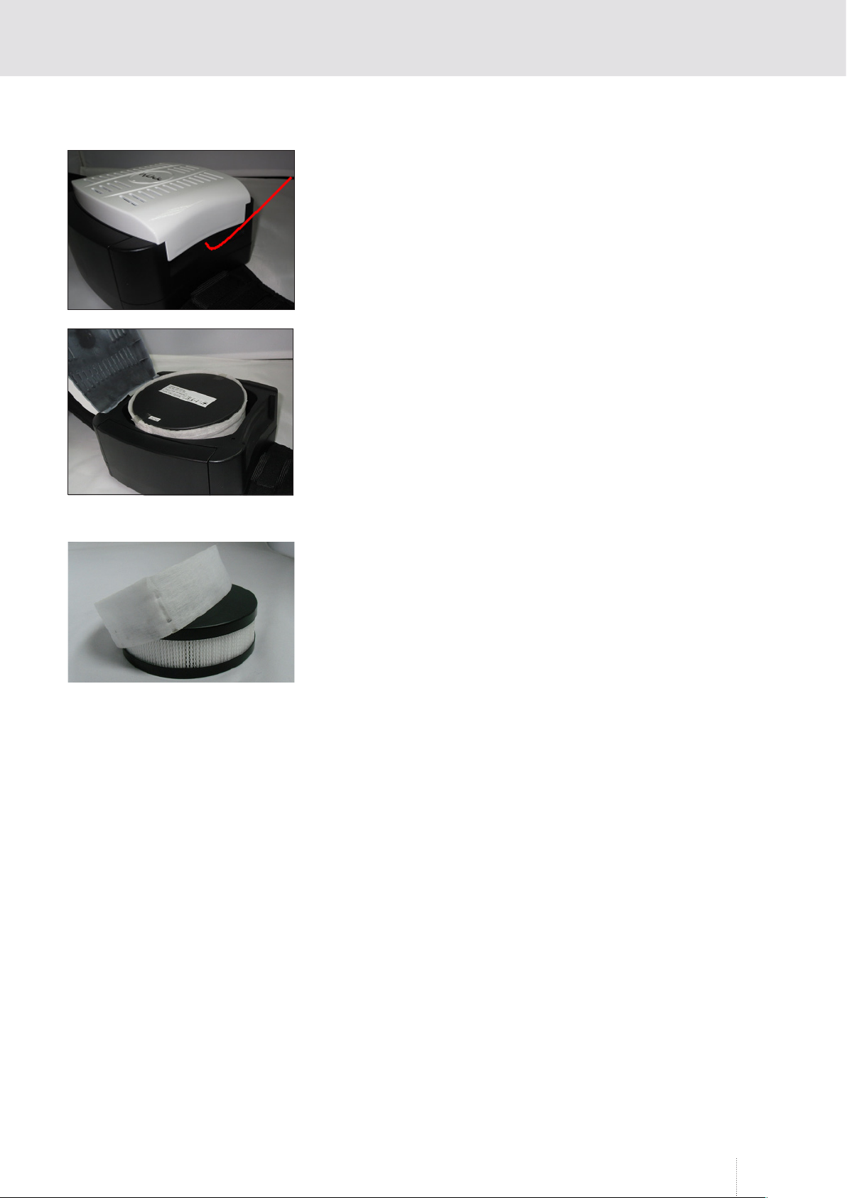
4.2.3 Removing the Filter
Opening the filter cover:
Grip the blower and pull up the cover from the right side to the blower.
ATTENTION ! lt is strictly forbidden to use any tools to open the filter cover.
To remove the filter, pull it off the filter seal while rotating it. Clean the unit
from dust.
4.2.4 Fitting a new Filter
Inserting a new filter:
Put the filter back into position using the same rotating motion and gently
push until it fits well on the body of the unit.
Closing the filter Cover:
Simply snap the cover into place. Pay special attention to snap the cover
properly into the blower. Do not attempt to use the blower unit without
the cover fitted correctly.
4.2.5 Changing the Pre-Filter
The Pre-Filter is a sleeve which is fitted over the main filter. To remove / re-
place simply pull off the old filter and stretch the new one into position. It‘s
important to ensure that the filter media of the main filter is completely
covered by the Pre-Filter.
4.2.6 Attaching the Hose to the Blower Unit
Align the pins of the Hose Bayonet connector with the slots in the air
outlet of the blower. Push the bayonet connector into the blower until it
reaches the bottom of the hole and then twist in a clockwise direction until
the locating pins clips into place.
Fitting the hose to the hoods is the same procedure.
4.2.7 Donning the Welding Helmet
First set the Welding helmets rake and adjust the welding filter to suit
personal comfort (See the helmet‘s user instructions). Lift the helmet to it‘s
upper position. Place over the head and adjust the headgear ratchet wheel
by pushing it in and twisting until a satisfactory tightness is achieved.
Pull the elasticated chin guard downwards and at the same time pull the
helmet down. Ensure the elasticated chin guard fits comfortably under the
chin. The Welding helmet is now ready for use.

12
5. Before use
5.1 Inspection before use
Each time before starting work check that:
• All components are in good condition with no visible damage (Iike holes,
tears etc.). Replace any damaged or worn parts. Carefully examine the
air hose, seals and the face piece.
• There is a good connection between the air hose and the headpiece as
well as the blower unit.
• There is sufficient air flow (see 5.2).
• The air is supplied through the whole respiratory system from the blo-
wer to the hood.
• Check the battery before the first use (see 5.3).
5.2 Air Flow Test
1. Disconnect the air hose fram the Blower unit.
2. Insert the Airflow indicator into the air hose connector and keep the
hose in vertical position at about the eye level.
3. Switch the power unit on. The airflow is sufficient only if the ball indi-
cator reaches the minimum flow rate level. If the indicator is below the
minimum flow rate level, it is necessary to charge the battery or change
the filter. If the problem still persists, see chapter 8 for additional sugge-
stions.
5.3 Batteries
The removable rechargeable battery used is a Lithium Ion cell. When
supplied the battery may hoId a small charge, the unit should be run flat
and then charged for sixteen hours before the first use.
NOTE! Batteries are delivered only partially charged. All batteries must be
charged before they are used for the first time. The battery can be charged
separately or on the blower unit.
The charger must not be used for any other purpose than that for which
it was manufactured. Do not charge the battery in a potentially explosive
atmosphere. The battery charger is intended for indoor use. It must be
protected against damp. The charger controls the charging automatically.
After the battery has been charged, the charger switches to the trickle
charging regime and keeps the battery fully charged. The charging time is
6 to 8 hours.

13
5.3.1 Battery charging
1. Check that the voltage of the electrical power supply is correct.
2. Plug the charger into the socket.
3. Connect the battery to the charger. The socket of the battery is positio-
ned on the back side.
4. The charging state is indicated by a red LED diode light.
5. After charging has been completed, the trickle charging regime is ac-
tivated: -red LED Diode goes out, the green LED diode comes on at the
moment of trickle charging.
5.3.2 Battery changing
Removing the battery:
1. Locate the battery catch.
2. Pull back the battery catch and at the same time the battery can be
removed by lifting upwards.
Fitting the battery:
Make sure the battery is the correct way up and then slide into the blower
until the battery catch engages.
It is essential that the battery catch is fully locked.
14
Usage
6. Usage
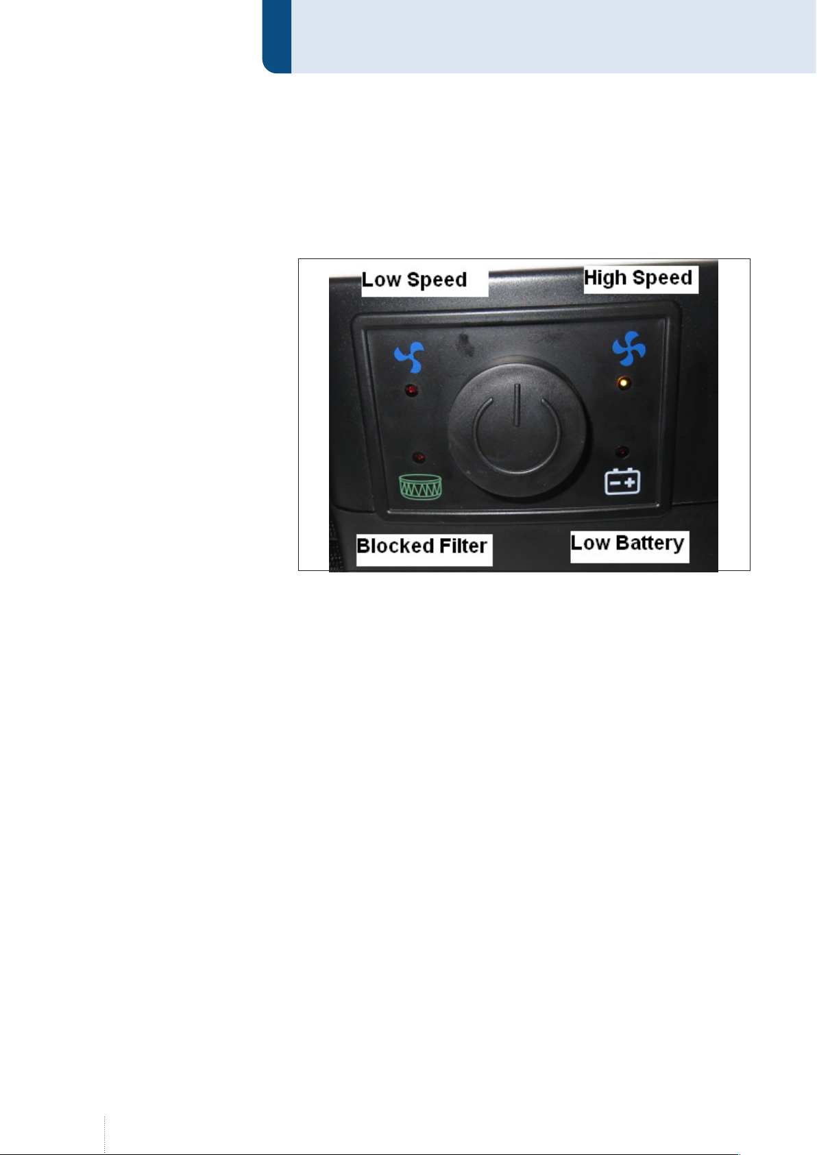
Switch on the unit by pressing the ON/OFF button on the control panel.
The airflow can be adjusted by two arrow-buttons from 180 I/min up to
220 I/min.
The unit ensures a constant supply of air. The microprocessor inside the
unit automatically regulates the motor speed to compensate the filter
clogging and the battery state. If the microprocessor cannot keep the ad-
justed airflow, the unit will sound a ‚beeping‘ alarm (an acoustic signal can
be heard). At which point the user must check the blower unit. If possible,
the microprocessor automatically reduces the airflow to the next lower
level, if it fails to meet the lower level, the alarm will still sound. When the
airflow falls below the minimum safe operating level, a second audible
alarm joins the first and the unit will vibrate. At this point, the user must
stop working at once, leave the working environment and reach an area
nominated to be safe and change the filter or recharge/change the battery.
To check the battery:
When first starting the unit, the battery LED must show red - this shows a
fully charged battery. It is recommended that only a fully charged battery
should be used when starting a work shift.
With a fully charged battery in place, the unit should function normally,
but if the audible alarm still sounds, the user must change the filter. If the
problem still persists, see chapter 8 for additional suggestions.

15
7. Maintenance / Cleaning
The Blower unit, filter housing and head units must all be regularly clea-
ned to keep them in good working order.
For single users, the units can all be cleaned with a cloth moistened with
lukewarm water and soap.
For multiple users, the units should be disinfected when passed from one
user to another.
The Manufacturer recommends that ‚Incidur‘ from Ecolab GmbH & Co.
OHG is used for disinfecting.
Liquids must not be allowed to enter the workings of the blower unit or
get on to the element of the filter.
Parts should be allowed to air dry. Under no circumstances should any
solvents or abrasive cleaning agents be used. The unit must not be dried
using hot air or radiant heat.
The unit should continue to provide protection to the designed specificati-
on for 2 to 3 years, when maintained in accordance with these instructions.
Prior to each use the user should check that the unit is free from defects,
such as cracks, split filters and hoses, cracked visors and helmet compo-
nents as appropriate

16
Fault finding
8. Fault finding
If there is a sudden change in air supply while using the blower unit, it is
necessary to check the following:
• that all parts of the air-supply system are assembled properly,
• the battery and its connector,
• whether the charger is not faulty or malfunctioning (if so, diodes do not
work),
• Filters and their clogging,
• That there is not a hole in the air hose,
• whether the hood seal is not damaged,
• whether the working time after a full recharging of the battery has not
decreased (if so, it is necessary to replace the battery).

17
9. List of parts
Welding Helmet Arc Flash 4 air 0875006250
Arc Flash 4 air helmet only 0875006251
Arc Flash 4 air Headgear cpl. 0875006252
Arc Flash 4 air face seal 0875006253
Arc Flash 4 air filter complete 0875006254
Arc Flash 4 air hose cover 0875006255
Arc Flash 4 air hose 0875006256
Arc Flash 4 air particle filter 0875006257
Arc Flash 4 air prefilter (10 pc) 0875006258
Arc Flash 4 air Li-Ion battery standard 0875006259
Arc Flash 4 air Li-Ion battery HD 0875006260
Arc Flash 4 air charger EU/AUS/UK/US 0875006261

18
List of parts
Arc Flash 4 air belt with lumbar support 0875006262
Arc Flash 4 air ventilation grill 0875006263
Arc Flash 4 air storage bag 0875006264

19

www.qineo.de
Carl Cloos Schweißtechnik GmbH
Industriestraße
D-35708 Haiger
Germany
Telefon +49 (0)2773 85-0
Telefax +49 (0)2773 85-275
E-Mail [email protected]
www.cloos.de
Other manuals for Arc Flash 4 evo
1
Table of contents
Other Cloos Welding Accessories manuals

Popular Welding Accessories manuals by other brands

AMERICAN WELDQUIP
AMERICAN WELDQUIP 550A manual

Kemper
Kemper MaxiFil Clean operating instructions

Abicor Binzel
Abicor Binzel Air-blast and injection unit operating instructions

Scheppach
Scheppach AWH-500FL Translation of original instruction manual

ESAB
ESAB A6 VEC instruction manual

Itm
Itm GECKO Operator's manual


ThermOweld
ThermOweld CX-4 instructions

SHINE
SHINE 5000 instruction manual

Abicor Binzel
Abicor Binzel xFUME ABIROB AF500 Instruction leaflet

Abicor Binzel
Abicor Binzel MF Control operating instructions

iBell
iBell IBL 550S Operator's manual

Professional Tool Products
Professional Tool Products PWH4000 quick start guide