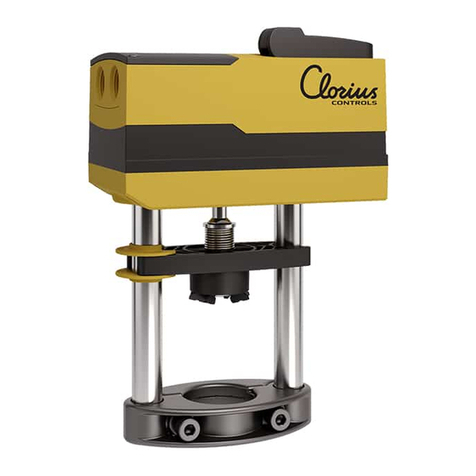
Clorius Controls AVM 321S Operational manual

AVM 321S, 322S: Valve actuator
How energy efficiency is improved
Automatic adaptation to valve, optimal operator convenience, precision activation and high energy ef-
ficiency with minimal operating noise
Features
•For actuation of 2- and 3-way valves
• For controllers with constant output (0...10 V / 4...20 mA) or switching output (2-point or 3-point con-
trol)
• BLDC motor (brushless DC) with SUT (Superior Universal Technology) electronic control unit of the
third generation and electronic load-dependent cut-off
• Automatic detection of applied control signal (continuous or switching), operating display with bi-col-
our LED
• Automatic adaptation to the stroke of the valve, between 10 and 20 mm
• Low operating noise
• With the built-in absolute distance measurement system, the position is always maintained in the
case of power failure
• The direction of operation, characteristic (linear/equal percentage), positioning time and control sig-
nal (voltage/current) can be adjusted via coding switches
• Integrated forced operation can be set via coding switches (with selectable direction of operation)
• Easy re-initialisation using a coding switch
• Crank handle for external manual adjustment with motor cut-off
• Simple assembly with valve; spindle is automatically connected after control voltage is applied
• Numerous adapters enable the unit to be fitted onto non-Clorius valves
• Electrical parallel operation of five actuators
• Parameterisation option via the BUS interface
• Three-piece housing made of flame-retardant yellow/black plastic and seals with type of protection
IP54
• Maintenance-free gearbox made of plastic; threaded spindle and gearbox base-plates made of steel
• Patented drive-valve coupling
• Mounting column made of aluminium
• Fixing bracket made of cast light alloy for valve fitting with 20 mm stroke and made of plastic for
valve fitting with 10 mm stroke
• Electrical connections (max. 1.5 mm²) with screw terminals
• Two break-out cable inlets for metric cable glands made of plastic M20 × 1.5
• Fitting position vertically upright to horizontal, not suspended
• Nominal thrust 1000 N2)
Technical data
Power supply
Power supply 24 V~ ±20%, 50...60 Hz
Power supply 24 V= –10...20%
Power supply 230 V~ ±15%
Power consumption < 1.7 W, < 3.5 VA
(at nominal voltage, with movement)
Parameters
Nominal force3) 1000 N
Operating noise4) < 30 dB (A) at nominal force
Response time > 200 ms
1) CSA-certified actuators on request
2) Actuating power 1000 N under nominal conditions (24 V, 25 °C ambient temperature, 50 Hz). With boundary
conditions (19.2 V~ / 28.8 V~ / 21.6 V= / 28.8 V=, -10 °C / 55 °C, 60 Hz) and positioning time, the actuating/
ten-sile force is minimised to 800 N
3) Noise level with the slowest positioning time, measuring distance 1m
Product data sheet 99.70.06-C
3.1 1/8
AVM32*S
www.cloriuscontrols.com

Temperature of medium5) 0...100 °C
Nominal voltage 24 V~/=
Characteristic Linear/equal percentage
Control signal y6) 0...10 V, Ri ≥ 50 kΩ
4...20 mA, Ri ≤ 50 Ω
Positional feedback y00...10 V, load ≥ 5kΩ
Starting point U00 or 10 V
Starting point I04 or 20 mA
Control span ΔU 10 V
Control span ΔI 16 mA
Hysteresis Xsh 160 mV
0.22 mA
Ambient conditions
Operating temperature -10...55 °C
Storage and transport temperature -40...80 °C
Humidity without condensation 5...85 % rh
Standards and directives
Type of protection IP 54 (EN 60529)
Protection class III (EN 60730-1), EN 60730-2-14
CE conformity according to EMC Directive 2004/108/EC EN 610000-6-1, EN 610000-6-2,
EN 610000-6-3, EN 610000-6-4
Low-voltage directive 2006/95/EC EN 60730-1, EN 60730-2-14
(AVM32*F110 and F120)
Over-voltage categories III
Degree of contamination II
Max. altitude 2000 m
Machine directive 2006/42/EC
(according to appendix IIB)
EN ISO 12100
Overview of types
Type Nominal voltage Positioning time
(s/mm)
Nominal stroke Dimensions W x
H x D
Weight
AVM321S 24 V~/= 12 (4) 10 mm 160 × 187 × 88 1.5
AVM322S 24 V~/= 6 (4) 20 mm 160 × 241 × 88 1.6
5) At media temperature > 100 °C appropriate accessory must be used (temperature adapter); at media tempera-
ture < 0 °C appropriate accessory must be used (stuffing box heater)
6) Positioner: also for 2- or 3-point, depending on type of connection
Product data sheet 99.70.06-C
2/8 3.1
Accessories
Type Description
1-0152285 Temperature adaptor for media temperature > 100 °C … 240 °C
1-0152313*4...20 mA feedback module
1-0152315*Constant power supply module for 85…265Vac 50/60Hz
1-0152665 Adjustable valve adaptor for for AVM322 and Clorius Controls valves up to 20 mm stroke
1-0152675 Adjustable valve adaptor for for AVM321 and Clorius Controls valves up to 10mm stroke
Cable glands M20×1.5
www.cloriuscontrols.com

Description of operation
Depending on the type of connection (see connection diagram), the actuator can be used as a contin-
uous (0...10 V or 4...20 mA), 2-point (OPEN/CLOSE) or a 3-point actuator (OPEN/STOP/CLOSE).
The positioning time of the actuator can be set with the S1 switches according to the respective re-
quirements. Using switch S2, the direction of operation can be changed.
In the end positions (valve limit stop or when the maximum stroke is reached) or upon overload, the
electronic motor cut-off (no limit switch) responds and turns off the motor.
The external crank handle enables manual positional setting. After the crank handle is folded back,
the actuator moves to the target position again (without initialisation). When the crank handle is folded
out, the actuator remains in this position.
Intended use
This product is only suitable for the purpose intended by the manufacturer, as described in the “De-
scription of operation” section.
All related product regulations must also be adhered to. Changing or converting the product is not ad-
missible.
Engineering and fitting notes
The concept of a brushless DC motor/electronics ensures electrical parallel operation of up to five ac-
tuators of the same type.
The valve is mounted directly on the actuator and fixed with screws (no further adjustments are re-
quired). The actuator is connected with the valve spindle automatically. As delivered ex works, the ac-
tuator spindle is in the middle position.
As delivered ex works, the actuator spindle is in the middle position.
Condensate, dripping water, etc. must be prevented from entering the actuator along the valve spin-
dle.
The housing contains two break-out cable inlets for two metric plastic cable glands M20×1.5, which
are broken out automatically when the cable inlet is screwed in.
If the cable resistance is > 1.5 Ω, the ground should be separated from the power supply and the sig-
nal if possible.
The cross-section of the power cable must be selected based on the cable length and the number of
actuators. With five parallel actuators and a cable length of 50 m, a cable cross-section of 1.5 mm2
and a line resistance of > 1.5 Ω must be used (power consumption of the actuator × 5).
According to building installation regulations, the lines must be protected from overload or short cir-
cuit.
)Note for UL and CSA applications:
In the United States, the installed lines and cross-sections which are to be connected by the customer
must comply with the requirements of NFPA70 (NEC), and in Canada they must comply with the require-
ments of the standard C22.1-12 (CE Code).
The coding switches and the SLC interface for CASE Drives are accessible via an opening in the con-
nection area of the actuator. Conversion and operation is possible while the actuator is energised.
Product data sheet 99.70.06-C
3.1 3/8
www.cloriuscontrols.com

)Note:
The actuators are not suitable for use
•in potentially explosive environments,
Specific standards such as IEC/EN 61508, IEC/EN 61511, EN ISO13849 and the like have not been
tak-en into account.
Local requirements regarding installation, usage, access, access rights, accident prevention, safety, dis-
mantling and disposal must be taken into account.
The housing must not be opened.
Outdoor installation
In case of installation outside buildings, the devices must also be protected from the weather.
Additional information
Fitting instructions P100014079 B
Declaration on materials and the environment
Declaration of incorporation
Power consumption at nominal voltage
Type Positioning time (s/mm) Status Active power P(W) Apparent power S (VA)
AVM321S 12 / (4) Operation < 1.7 < 3.5
Standstill < 0.45
Sizing ≥ 4.5
AVM322S 6 / (4) Operation < 1.7 < 3.5
Standstill < 0.45
Sizing ≥ 4.5
Connection as 2-point valve actuator (24 V)
The OPEN/CLOSE activation is via two wires.
The actuator is connected to a permanent voltage via terminal MM and terminal 01.
When voltage (24 V) is applied to terminal 02, the actuator spindle extends into the end position.
After the voltage is switched off at terminal 02, the actuator automatically retracts into the base posi-
tion.
Terminal 03 may not be connected or touch other contacts. We recommend that you insulate these.
Connection as 3-point valve actuator (24 V)
If voltage is applied to terminals MM and 01 (or 02), the valve can be moved to any position.
If voltage is applied to terminals MM and 01, the actuator spindle retracts.
If the electrical circuit is closed on terminal MM and 02, the actuator spindle extends.
If there is no voltage on terminals 01 and 02, the actuator remains in the respective position until volt-
age is applied.
Terminal 03 may not be connected or touch other contacts. We recommend that you insulate these.
Connection to a control voltage (0...10 V or 4...20 mA)
The built-in positioner controls the actuator depending on controller’s output signal y. A voltage signal
(0...10 V) at terminal 03 serves as the control signal. Coding switch S4 can be used to switch to a
current input (4...20 mA). If there is voltage on terminals MM/01 and a rising positioning signal, the
actuator spindle extends. The direction of operation can be reversed with coding switch S2.
The starting point and control span are fixed. For setting partial ranges (only for voltage input), a split-
range unit is available as an accessory (see split-range unit function).
After the connection of the power supply and the initialisation, the actuator moves to every valve
stroke between 0% and 100%, depending on the control signal. Thanks to the electronics and the ab-
solute distance measurement system, no stroke is lost, and the actuator does not require periodic re-
initialisation.
If the control signal 0...10 V is interrupted in the direction of operation 1, the actuator spindle retracts
completely.
If the control signal 0...10 V is interrupted in the direction of operation 2, the actuator spindle extends
completely. This is true if the forced operation is switched off. (Coding switch S5 OFF)
Product data sheet 99.70.06-C
4/8 3.1
www.cloriuscontrols.com

With coding switch S3, the characteristic of the valve/actuator combination can be adjusted. An
equal-percentage characteristic can only be generated when the actuator is used as a continuous ac-
tuator.
Initialisation and feedback signal
The actuator initialises itself automatically when it is connected as a continuous actuator (not in 2-/3-
point mode).
When a voltage is applied to the actuator for the first time, the actuator first moves to the first and
then to the second valve limit stop, or to the internal actuator stop. The two values are recorded and
stored by the absolute distance measurement system. The control signal and the feedback are adap-
ted to this effective stroke.
After initialisation, the actuator goes to every valve stroke between 0% and 100%, depending on the
control voltage.
In case of a power failure or the removal of the power supply, no re-initialisation needs to be carried
out. The values remain saved.
If the initialisation is interrupted, the initialisation is started again when the voltage is re-applied.
You trigger a re-initialisation by switching coding switch S8 from OFF to ON or vice versa.
When the process is triggered, the LED flashes green.
During initialisation, the feedback signal is inactive or equal to the value “0”. The initialisation is car-
ried out with the shortest positioning time. The re-initialisation is only valid when the whole process is
complete.
If a stroke change is carried out, a re-initialisation must be triggered so that the new stroke can be
adapted.
If the valve actuator detects jamming, it reports this by setting the feedback signal to 0 V after approx.
90 s. During this time, the actuator continues to try to overcome the jamming. If the jamming can be
overcome, the normal control function is activated again and the feedback signal is restored.
With 2-point or 3-point control without a feedback signal, no initialisation is performed.
Continuous control can also be implemented with a 230 V power supply with the external accessory
0500570003 “230 V module”. You must ensure that the neutral wire of the controller is connected to
the control voltage. The neutral wire of the power supply may only be used for the 230 V module.
B12671
Forced operation (in continuous mode)
Forced operation is activated via coding switch S5.
To use this function, an external on/off controller must be attached to terminal 6. The on/off controller
functions as normally-closed contacts.
If the on/off controller opens the electrical circuit, the actuator spindle moves to the end position de-
fined by coding switch S6.
Forced operation can be used only in continuous mode.
2-/3-point operation using the reset signal
If terminal 6 is continuously connected to the power and coding switch S5 is set to OFF, the feedback
signal 0...10V can be used.
When this function is used, the actuator automatically performs an initialisation during commissioning.
Split-range module, accessory 0500420002
Starting point U0 and control span U can be set with the potentiometer. In this way, several control
units can be operated in sequence or cascade by the control signal of the controller. The input signal
(partial range) is amplified into an output signal of 0...10V.
CASE Drives PC tool, accessory 0510220001
CASE Drives allows you to set and read the actuator parameters on site. The connection is via a seri-
al port on the PC (laptop) and a socket on the actuator. The set consists of: The software including
installation and operating instructions, fitting instructions, connection plug, cable (1.2 m long) and in-
Product data sheet 99.70.06-C
3.1 5/8
www.cloriuscontrols.com

terface converter for the PC. The application is designed for commissioning and service engineers as
well as experienced operators.
Feedback signal converters, accessory 1-0152313*
With the feedback signal converter accessory (drawing no. 0500420002), the output signal yo is
converted from a voltage signal 0...10 V into a current signal 4...20 mA.
Coding switch
e
d g
n
ullet
sr
etl
a
h
c
S
rf ud
noiti
s
o
P
r
u
e
t
at
umm
o
c
n
e n
oi
t
i
s
o
p
hctiw
S
t
i en
oizi
s
o
P
er
ott
urr
et
n
i‘lle
d
s
e r
otp
u
rr
e
t
ni
l
ed
n
ói
c
i
s
o
P
v
s e
g
ä
l
rat
yr
B
l
n d
n
ats
r
a
al
e
k
a
h
c
S
e
d nnis
kri
W
rf n
oi
t
c
a‘
d
s
n
e
S
n
e fo
n
oi
t
c
e
r
iD
n
o
it
ar
e
p
o
ti e
n
oiz
e
r
iD
e
n
o
i
z
a‘l
l
e
d
s
e e
d
odit
n
e
S
od
n
am
v
s g
ni
n
t
kirt
fir
D
l
n g
n
it
h
cir
s
g
n
i
kr
e
W
e
d *
b
eirt
n
A
ei
n
il
n
n
e
K
rf b
r
u
oC
u
d e
u
q
it
sir
étc
ar
a
c
ruet
o
m
ov
r
es
n
e r
ot
aut
c
A
ci
t
sir
etc
ar
a
h
c
ti a
citsir
ett
a
rac avruC
er
o
t
a
utt
a
s
e a
citsír
e
tcara
c
avru
C
r
ot
om
le
d
v
s gn
i
n
v
ird
,
a
vruK
l
n keitsiret
k
araK
gnivj
i
r
dnaa
ed *
l
angislletS
rf ed
l
ang
i
S
i
sop tnemenn
oit
ne langis
g
nino
it
isoP
t
i id el
an
g
eS
e
n
oizaloger
se o
d
nam
e
d lañeS
vs lang
isry
t
S
ln l
aangisruutS
e
d *
g
nureuetssgn
a
wZ
rf eécr
of ednammoC
n
e no
it
ar
ep
o
d
e
croF
ti otazrof odnamoC
s
e
od
n
aM
o
c
imórdom
s
ed
v
s li
t
n
ev dr
ytssgnåvT
l
n g
nir
u
tse
b
g
nawD
ed -sg
n
awZ
tk
nups
s
eilh
c
S
*g
n
ur
e
uet
s
rf
al e
d
er
u
temref
e
d tni
o
P
e
écrof
e
dnam
moc
ne
dec
r
of rof tniop gnis
o
lC
noitarep
o
ti i
d ot
n
up ota
zrof od
n
amo
C
o
igga
ccolb
se odna
m
le
d erreic
ed o
tn
u
P
ocimórd
omse
d
v
s d
r
yt
s
s
gnå
v
t
,tkn
u
psgningnätS
li
tnev
ln g
nirutsebgn
a
w
d
t
nu
pt
i
u
l
S
mm/
s
2
1 :
1
2
3M
V
A
mm/
s
6
:
2
2
3M
VA
100%
0%
Signal
lin V
0
1.
..
0 C
D
prio.
off
m
m
/
s 4 :123MVA
mm/
s 4 :
2
23
M
V
A
100%
0%
Signal
stroke
= %
INV
de *Gilt nur für stetig Modus
fr *S‘applique uniquement aumode de régulation continue
en *Applies for continuous mode only
it *Vale solo per modo „continuo“
es *Se aplica sólo para modo continuo
sv *Gäller endast för kontinuerlig reglering
nl *Geldt uitsluitend voor continu modus
Am 02.
.
.4
prio.
on
e
d ti
e
zl
l
et
S
rf ed
s
pm
e
T
t
n
em
e
n
n
o
it
i
s
o
p
n
e emit
g
n
i
n
oi
t
i
s
o
p
t
i a
rv
o
n
am i
d
o
pm
e
t
se et
s
u
j
a
e
d
o
pm
e
i
t
v
s di
tll
äts
l
n dj
itl
et
s
LED
LED Description
Flashes green (T1s) Valve adapting, initialisation
Flashes green (T3s) Position reached
Lights up green Actuator spindle moves IN/OUT
Flashes orange Manual adjustment activated
Flashes red Actuator jammed, actuator at end stop
Lights up red Incorrect configuration of forced operation, undervoltage, insufficiently adapted stroke
Disposal
When disposing of the product, observe the currently applicable local laws.
More information on materials can be found in the Declaration on materials and the environment for
this product.
Product data sheet 99.70.06-C
6/8 3.1
www.cloriuscontrols.com

Connection diagram
Modulating action
01MM
2pt
03
05
06
24 V~/=
02
yo=0...10V
y=0...10 V
y=4...20m A
24 V~/=
05MM 0301
0%
100%
Spindle
02 06
3pt
24 V~/=
01MM 03
05
06
02
M
µC
A10765
2pt/3pt multi-position action with feedback signal
01
MM
2pt
03
05
06
24 V~/=
02
yo=0...10 V
01
MM
3pt
03
05
06
24 V~/=
02
yo=0...10 V
A10764
Modulating action with forced operation
yo=0...10 V
24 V~/=
05MM 0301
0%
100%
Spindle
02 06
µC
A10766
y=0...10 V
y=4...20 mA
Product data sheet 99.70.06-C
3.1 7/8
www.cloriuscontrols.com

Dimension drawing
Type a b c
AVM 321 53 187.4 33
AVM 322 64 241 44
Accessories
141
137
31
71
87
78
M11518
Product data sheet 99.70.06-C
8/8 3.1
www.cloriuscontrols.com
This manual suits for next models
1
Table of contents
Other Clorius Controls Controllers manuals
Popular Controllers manuals by other brands

Netafim
Netafim nmc-pro installation guide

DMP Electronics
DMP Electronics X1 COMPLIANCE GUIDE
Lenze
Lenze 712 operating instructions
Baldor
Baldor VS1GV21-1B Installation & operating manual

Minleon
Minleon Multifunction Mini Controller instruction manual
Panasonic
Panasonic AKHRP900P - CAMERA CONTROLLER HC Service manual
OTEK
OTEK FS Series quick start guide
Webasto
Webasto SmarTemp Control fx Installation and operation instructions
PIETRO FIORENTINI
PIETRO FIORENTINI REFLUX 819 Technical manual
Franklin Electric
Franklin Electric InlineSWC Quick setup guide

Zener
Zener MSC-3 instruction manual
Grozone Control
Grozone Control Dual Zone CO2 Controller manual
