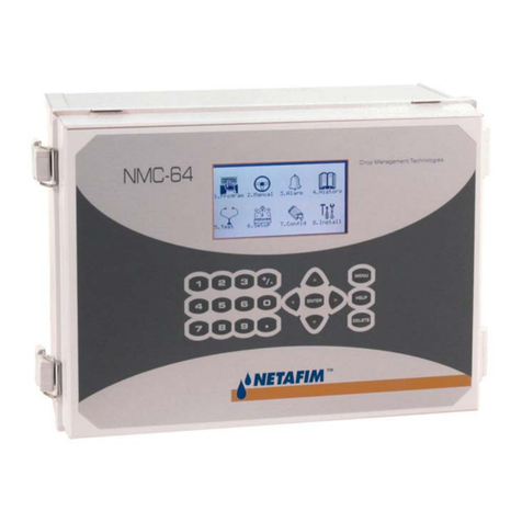
Netafim nmc-pro User manual

[Type text]

NMC-PRO User Manual
Page 2
© COPYRIGHT 2011, NETAFIM test
NO PARTS OF THIS PUBLICATION MAY BE REPRODUCED, STORED IN AN AUTOMATED DATA FILE OR MADE PUBLIC IN
ANY FORM OR BY ANY MEANS, WHETHER ELECTRONIC, MECHANICAL, BY PHOTOCOPYING, RECORDING OR IN ANY
OTHER MANNER WITHOUT PRIOR WRITTEN PERMISSION OF THE PUBLISHER.
ALTHOUGH NETAFIM TAKES THE GREATEST POSSIBLE CARE IN DESIGNING AND PRODUCING BOTH ITS PRODUCTS
AND THE ASSOCIATED DOCUMENTATION, THEY MAY STILL INCLUDE FAULTS.
NETAFIM WILL NOT ACCEPT RESPONSIBILITY FOR DAMAGE RESULTING FROM THE USE OF NETAFIM'S PRODUCTS OR
THE USE OF THIS MANUAL.
NETAFIM RESERVES THE RIGHT TO MAKE CHANGES AND IMPROVEMENTS TO ITS PRODUCTS AND/OR THE
ASSOCIATED DOCUMENTATION WITHOUT PRIOR NOTICE
VERSION 3.07 REV 1.8 110045
.

NMC-PRO Installation Manual
3Page
CONTENTS
Table of Contents
1General Instructions ................................................................................................................................................ 9
1.1 Basic Requirements for On-Site Preparation ...................................................................................................9
1.2 Frequency Inverters..........................................................................................................................................9
1.3 General Dimensions .........................................................................................................................................9
2Unpacking and Mounting...................................................................................................................................... 10
2.1 Unpacking.......................................................................................................................................................10
2.2 Controller Mounting ........................................................................................................................................10
3POWER SUPPLY WIRING ..................................................................................................................................... 11
3.1 Main Power Wiring..........................................................................................................................................11
3.2 Power Supply Options ....................................................................................................................................13
3.2.1 Power Supply Option A ............................................................................................................................. 13
3.2.2 Power Supply Option B ............................................................................................................................. 13
3.3 Cold Start ........................................................................................................................................................14
3.4 Set Language, Time and Date........................................................................................................................15
3.5 Electric Test ....................................................................................................................................................15
3.6 Firmware Upgrade ..........................................................................................................................................16
3.6.1 Accessing the Application ......................................................................................................................... 16
3.6.2 Running the Application ............................................................................................................................ 17
4ELECTRICAL INSTALLATION............................................................................................................................... 18
4.1 Input/Output ....................................................................................................................................................18
4.1.1 Layout........................................................................................................................................................ 18
4.1.2 I/O Card Layout ......................................................................................................................................... 19
4.1.3 Controller Hardware Verification ............................................................................................................... 20
4.1.4 Input/Output Wiring.................................................................................................................................... 20
4.2 Output Terminal ..............................................................................................................................................21
4.2.1 Analog Output Card................................................................................................................................... 21
4.2.2 24 VAC Connection................................................................................................................................... 23
4.2.3 Dry Contact Card....................................................................................................................................... 24
4.3 Input Terminals ...............................................................................................................................................25
4.3.1 Wiring ........................................................................................................................................................ 25
4.3.2 Analog Input Card...................................................................................................................................... 27
4.4 Expansion Unit Connection: Card Connection Options..................................................................................31
4.4.1 Option A: RS-485 Connection ................................................................................................................... 32
4.4.2 Option B: RS-232 Direct Connection......................................................................................................... 34
4.4.3 Option C: RS-232 via Line Driver Connection........................................................................................... 35
4.4.4 Wrong Relay Connection .......................................................................................................................... 36
4.4.5 Expansion Unit .......................................................................................................................................... 36

NMC-PRO Installation Manual
4Page
CONTENTS
4.4.6 PC and Inter-Controller Communication ................................................................................................... 37
4.5 Controller Setup..............................................................................................................................................40
4.5.1 Start-Up ..................................................................................................................................................... 40
4.5.2 Hardware Checklist ................................................................................................................................... 40
4.5.3 Output Definition........................................................................................................................................ 41
4.5.4 Digital Input Definition ............................................................................................................................... 41
4.5.5 Analog Input Definition .............................................................................................................................. 42
4.5.6 Analog Output Definition ........................................................................................................................... 42
4.6 Controller Test Procedure...............................................................................................................................43
4.6.1 Test Relays................................................................................................................................................ 43
4.6.2 Digital Input Test........................................................................................................................................ 44
4.6.3 Analog Input Test ...................................................................................................................................... 44
4.6.4 Analog Output Test.................................................................................................................................... 45
4.7 System Configuration Procedure....................................................................................................................46
4.7.1 Device Delay Configuration....................................................................................................................... 47
4.7.2 Pump Station Configuration ...................................................................................................................... 48
4.7.3 Valve Configuration ................................................................................................................................... 48
4.7.4 Valve Flow Rate Configuration.................................................................................................................. 48
4.7.5 Water Meter Configuration ........................................................................................................................ 49
4.7.6 Dosing Channel Configuration .................................................................................................................. 49
4.7.7 Analog Dosing Channel Configuration ...................................................................................................... 50
4.7.8 Dosing Configuration................................................................................................................................. 50
4.7.9 EC/PH Sensor Range ............................................................................................................................... 51
4.7.10 History Resolution ..................................................................................................................................... 51
4.7.11 System Nutrigation™ Check ..................................................................................................................... 52
4.7.12 Data Plug................................................................................................................................................... 54
5PROGRAM menu.................................................................................................................................................... 55
5.1 Irrigation ..........................................................................................................................................................55
5.1.1 Setting Irrigation that is Longer than 24H.................................................................................................. 59
5.2 Influence Program ..........................................................................................................................................59
5.2.1 Using the Influences .................................................................................................................................. 59
5.2.2 Setting the Influences ................................................................................................................................ 59
5.3 Water Run Time..............................................................................................................................................65
5.4 Dosing.............................................................................................................................................................66
5.4.1 Dosing Program......................................................................................................................................... 66
5.4.2 Dosing Injection Methods .......................................................................................................................... 67
5.5 Ext. Condition .................................................................................................................................................68
5.5.1 Defining Analog Sensors........................................................................................................................... 69

NMC-PRO Installation Manual
5Page
CONTENTS
5.6 Agitator............................................................................................................................................................70
5.7 Selector...........................................................................................................................................................71
5.8 Filter Flushing .................................................................................................................................................71
5.9 Cooling............................................................................................................................................................72
5.10 Misting.............................................................................................................................................................74
5.11 Water Heating.................................................................................................................................................75
6MANUAL OPERATION Menu ................................................................................................................................ 76
6.1 Irrigation Pause...............................................................................................................................................76
6.2 Start/Stop Program .........................................................................................................................................76
6.2.1 Start/Stop Valve......................................................................................................................................... 77
6.3 Filter Flushing .................................................................................................................................................77
7ALARM MENU ........................................................................................................................................................ 78
7.1 Alarm Reset ....................................................................................................................................................78
7.2 History.............................................................................................................................................................79
7.3 Alarm Definition ..............................................................................................................................................79
7.4 Alarm Setting ..................................................................................................................................................81
7.4.1 Analog Output Alarm Generation .............................................................................................................. 81
7.5 EC/pH Alarm Definition...................................................................................................................................82
7.6 EC/pH Alarm Setting.......................................................................................................................................83
7.7 Radio Sys. Alarm Definition............................................................................................................................83
7.8 Radio Sys. Alarm View ...................................................................................................................................84
7.9 SMS Subscription ...........................................................................................................................................84
8HISTORY MENU ..................................................................................................................................................... 85
8.1 Irrigation Log ...................................................................................................................................................86
8.2 RAD. / VPD Sum & Drain Log ........................................................................................................................86
8.3 Uncompleted Irrigation....................................................................................................................................87
8.4 Uncompleted Programs ..................................................................................................................................88
8.5 Daily Irrigation.................................................................................................................................................88
8.6 Irrigation Accumulation ...................................................................................................................................89
8.7 AUX Meter Accumulation................................................................................................................................89
8.8 Accumulation Reset........................................................................................................................................89
8.9 Filters ..............................................................................................................................................................90
8.10 Cooling............................................................................................................................................................90
8.11 Sensors Log....................................................................................................................................................91
8.12 Event Log........................................................................................................................................................91
8.13 System Log.....................................................................................................................................................91
9TEST MENU ............................................................................................................................................................ 92
9.1 Relays .............................................................................................................................................................92

NMC-PRO Installation Manual
6Page
CONTENTS
9.2 Digital Input.....................................................................................................................................................93
9.3 Analog Input....................................................................................................................................................94
9.4 Temperature ...................................................................................................................................................94
9.5 Humidity..........................................................................................................................................................95
9.6 Hardware Check List ......................................................................................................................................95
9.7 Analog Output Test.........................................................................................................................................96
10 Setup ................................................................................................................................................................. 97
10.1 Time & Date....................................................................................................................................................98
10.2 System Setup .................................................................................................................................................98
10.3 Temperature Calibration...............................................................................................................................101
10.4 Humidity Calibration......................................................................................................................................101
10.5 EC/pH Calibration .........................................................................................................................................102
10.5.1 Calibration of the EC/pH Monitor Transmitter ......................................................................................... 102
10.5.2 EC/pH Transmitter Monitor & NMC-Pro Correlation ............................................................................... 104
10.6 Pressure Calibration .....................................................................................................................................104
10.7 Weather Station Calibration..........................................................................................................................104
10.8 Sensors Logging...........................................................................................................................................105
10.9 Write to Data Plug.........................................................................................................................................105
10.10 Read from Data Plug ....................................................................................................................................106
10.11 Edit SMS Phonebook....................................................................................................................................107
10.12 SMS Setup....................................................................................................................................................107
10.13 SMS Personal Message ...............................................................................................................................108
11 CONFIGURATION MENU ............................................................................................................................... 109
11.1 Device Delay Configuration ..........................................................................................................................110
11.1.1 Example of Device Startup & Shutdown Order ....................................................................................... 110
11.1.2 Example of Stagger Valve Delay – Multiple Shifts .................................................................................. 111
11.2 Pump Station Configuration..........................................................................................................................112
11.3 Valve Configuration ......................................................................................................................................113
11.4 Valve Flow Rate............................................................................................................................................114
11.5 Water Meter ..................................................................................................................................................115
11.6 Dosing Channel Configuration......................................................................................................................116
11.6.1 Calibrating the Analog Dosing Valve....................................................................................................... 117
11.7 Dosing Configuration ....................................................................................................................................119
11.8 EC Pre-Control Configuration.......................................................................................................................120
11.9 Drainage Configuration.................................................................................................................................120
11.10 System Pressure Configuration ....................................................................................................................121
11.11 EC/pH Range Definition................................................................................................................................121
11.12 Pressure Sensor Range Definition ...............................................................................................................121

NMC-PRO Installation Manual
7Page
CONTENTS
11.13 Cooling Configuration ...................................................................................................................................122
11.14 Misting Configuration ....................................................................................................................................122
12 INSTALLATION Menu .................................................................................................................................... 123
12.1 Device Layout ...............................................................................................................................................123
12.2 Device List ....................................................................................................................................................125
12.3 Digital Input...................................................................................................................................................125
12.4 Analog Input 1-2 ...........................................................................................................................................126
12.5 Analog Output...............................................................................................................................................129
12.6 Hardware Checklist.......................................................................................................................................129
13 CONTROLLER ADVANCED SETTINGS........................................................................................................ 130
13.1 Pump Station Configuration..........................................................................................................................130
13.2 Multiple Water Meters...................................................................................................................................131
13.2.1 Option A - Standard Use/Measurement .................................................................................................. 131
13.2.2 Option B - Multiple Water Sources .......................................................................................................... 131
13.3 Drain Meter Measurement ............................................................................................................................132
13.3.1 Drainage Timing Option A ....................................................................................................................... 132
13.3.2 Drainage Timing Option B ....................................................................................................................... 133
13.4 Various Dosing Channel Configurations.......................................................................................................134
13.4.1 Method 1.................................................................................................................................................. 134
13.4.2 Method 2.................................................................................................................................................. 134
13.4.3 Method 3.................................................................................................................................................. 135
13.5 Dosing Configuration ....................................................................................................................................135
13.6 Dual EC/pH Sensors.....................................................................................................................................136
13.7 Hot Keys and Status Screens.......................................................................................................................138
13.8 Operation Mode ............................................................................................................................................138
14 APPENDIX A – NMC-PRO PARTS LIST........................................................................................................ 140
15 APPENDIX B – TROUBLESHOOTING .......................................................................................................... 141
15.1 Controller Malfunction...................................................................................................................................141
15.2 Burnt Fuse - In Case of Voltage ...................................................................................................................141
16 APPENDIX C – REPLACEMENTS AND ADDITIONAL INSTALLATIONS ................................................... 142
16.1 Installing a 24 VAC Output Card ..................................................................................................................142
16.2 Removing a Card..........................................................................................................................................143
16.3 Adding a Dry Contact Output Card...............................................................................................................143
16.4 Adding an Input Card....................................................................................................................................144
16.5 LCD & Keyboard Replacement ....................................................................................................................145
16.5.1 NMC-PRO: Old LCD & Keyboard Replacement ..................................................................................... 145
16.5.2 NMC-PRO: New LCD & Keyboard Replacement.................................................................................... 146
17 APPENDIX D - SENSOR INSTALLATION AND DEFINITION....................................................................... 147

NMC-PRO Installation Manual
8Page
CONTENTS
17.1 EC – pH Sensor Connection ........................................................................................................................147
17.1.1 EC Sensor Calibration ............................................................................................................................. 148
17.1.2 pH Sensor Calibration ............................................................................................................................. 149
17.1.3 Pro pH Calibration ................................................................................................................................... 150
17.2 Measuring Box Connection ..........................................................................................................................151
17.3 Humidity Sensor Definition ...........................................................................................................................152
17.3.1 Outside Temperature/Humidity Sensor Connection................................................................................ 153
17.3.2 Sensor Definition ..................................................................................................................................... 153
17.4 Pyranometer Connection – Netafim1 ...........................................................................................................154
17.5 Radiation Sensor Definition ..........................................................................................................................155
17.5.1 Radiation Sensor Configuration – Netafim .............................................................................................. 155
17.5.2 Radiation Sensor Connection – Davis..................................................................................................... 156
17.6 Pressure Transducer Connection.................................................................................................................157
17.6.1 Analog Pressure Sensor Definition ......................................................................................................... 158
17.7 Wind Direction Connection ...........................................................................................................................159
17.7.1 Wind Direction Sensor Definition............................................................................................................. 160
17.7.2 Wind Speed Digital Input Definition......................................................................................................... 160
17.8 Sensor and Cable Specifications..................................................................................................................161
18 APPENDIX E- TECHNICAL SPECIFICATIONS ............................................................................................. 162
18.1 Technical Specifications ...............................................................................................................................162
18.2 Controller Components.................................................................................................................................162
18.2.1 Keyboard & Display................................................................................................................................. 162
18.2.2 CPU ......................................................................................................................................................... 163
18.2.3 Power Supply .......................................................................................................................................... 163
18.2.4 Digital Input.............................................................................................................................................. 165
18.2.5 Analog Input ............................................................................................................................................ 165
18.2.6 Analog Output.......................................................................................................................................... 165
19 APPENDIX F - MAIN MENU TREE................................................................................................................. 166
20 WARRANTY .................................................................................................................................................... 167

NMC-PRO Installation Manual
9Page
GENERAL INSTRUCTIONS
1 GENERAL INSTRUCTIONS
•Installation should be performed by authorized technicians only.
•Verify that field components are working properly.
•Apply all safety regulations.
•Do not apply force or pressure on components during the installation procedure.
•Refer to your supervisor if problems occur during installation procedure.
1.1 Basic Requirements for On-Site Preparation
•Verify power source between 115 VAC or 220 VAC or 12VDC. (Australia & New Zealand 240 VAC±5%).
•Verify grounding connection < 10Ω.
•Environment temperature between (-10° C / 14° F)-(+60° C / 140° F).
•Verify protection from damaging climate conditions.
1.2 Frequency Inverters
Frequency inverters can cause severe electrical and electromagnetic interference. Therefore, when employing a
frequency inverter, it is critical that you carefully follow the manufacturer's installation instructions.
In particular verify:
•that the cable shielding between the inverter and any motor meets industry standards
•proper grounding of the inverter's chassis and motor power cable
•proper grounding of low voltage cable shield wire
•that the controller and inverter cables are kept in separate conduits or wire bundles
1.3 General Dimensions

NMC-PRO Installation Manual
12Page
ELECTRICAL INSTALLATION

NMC-PRO Installation Manual
13Page
ELECTRICAL INSTALLATION
3.2 Power Supply Options
•Power Supply Option A
•Power Supply Option B
3.2.1 Power Supply Option A
In case of remote consumers or low voltage on the main power, there is an option to use a 29 VAC supplier as shown:
3.2.2 Power Supply Option B
In case of voltage discrepancy or fluctuation in the main voltage, there is an option of connecting the system to an
independent supplier and keeping the main voltage as power source for the output devices as shown:

NMC-PRO Installation Manual
15Page
ELECTRICAL INSTALLATION
3.4 Set Language, Time and Date
Note: In any given menu, you can use arrow and ENTER keys on the touch pad to make a selection, or press the
corresponding number and ENTER on touch pad as a short cut.
3.5 Electric Test

NMC-PRO Installation Manual
16Page
ELECTRICAL INSTALLATION
3.6 Firmware Upgrade
The Bootloader application enables installing or updating the system firmware. The application is menu based and
simple to use and enables updating the firmware from an SD card.
Note: Verify that the card is in place before starting.
3.6.1 Accessing the Application
1. Press and hold the Left and Down arrow keys.
2. Turn on the unit.
In the screen that appears, enter the password: 38845.
Note: If you enter the wrong password, an error message appears and the program goes to the Main Screen.
Repeat the process.
3. Press Enter. The screen below appears.
Note: Hardware Test is used for quality control only.
SELECT AN OPTION
Hardware Firmware
Hardware Test
Cancel Update

NMC-PRO Installation Manual
17Page
ELECTRICAL INSTALLATION
3.6.2 Running the Application
Note: Pressing Exit or ESC takes you to the previous menu.
1. Select Hardware Firmware. The following screen appears (example only):
2. Select the required directory.
3. Press Enter.
The following screen appears:
4.Select the required software version.
5. Press Enter.
6. A confirmation message appears. Select Yes.
7. Press Enter.
Note: Do not turn the unit off during the update! If there is an interruption (for example a power outage), restart the
process.
At the end of the process, the following screen appears (the version numbers are examples only):
8. Press Enter and perform a Cold Start.
New Software Version
New Software Found
COLD START REQUIRED!!
Old Version:
8.02.00
New Version:
8.02.49
Press ENTER To Continue.
SELECT A FILE
Path: /
NMC_PRO <DIR> 13/Oct/2009
NETAFIMHEX1.04
<DIR>
12/Sept/2014
NETAFIMHEX1.06
<DIR>
12/Sept/2014
SELECT A FILE
Path: /
NMC_PRO <DIR> 13/Oct/2009
NETAFIM
<DIR>
12/Sept/2014
NEWPRO~1
<DIR>
12/Sept/2014
Press ENTER to confirm selection or MENU to return.

NMC-PRO Installation Manual
18Page
ELECTRICAL INSTALLATION
4 ELECTRICAL INSTALLATION
•Input/Output, page 21
•Output Terminal, page 21
•Input Terminals, page 25
•Expansion Unit Connection: Card Connection Options, page 31
•Controller Setup, page 40
•Controller Test Procedure, page 42
•System Configuration Procedure, page 45
4.1 Input/Output
•Layout, page 18
•I/O Card Layout, page 19
•Controller Hardware Verification, page 20
•Input/Output Wiring, page 20
4.1.1 Layout
The following diagram is an example setup of an NMC Pro board. Actual boards may differ.

NMC-PRO Installation Manual
19Page
ELECTRICAL INSTALLATION
4.1.2 I/O Card Layout
Modular I/O Bus:
•Up to 10 I/O Cards
•5 I/O Card Options
24 VAC Output Card
Dry Contact Output Card
SingleNet Dummy Card
Digital Input card
Analogue Input Card
Analog Output Card
•LED Status Lights for:
24 VAC Output Card
Dry Contact Output Card
Digital Input Card
SingleNet Dummy Output Card
The diagram above is an example setup. Actual setups may differ.
Analog Output Cards must be installed in the slots shown above.

NMC-PRO Installation Manual
20Page
ELECTRICAL INSTALLATION
4.1.3 Controller Hardware Verification
4.1.4 Input/Output Wiring
Other manuals for nmc-pro
2
Table of contents
Other Netafim Controllers manuals

Netafim
Netafim FROSTIE Manual

Netafim
Netafim NLC-100SH Programming manual

Netafim
Netafim Orbia GrowSphere MAX User manual

Netafim
Netafim AlphaDisc CLD User manual

Netafim
Netafim NMC-PRO CLIMATE User manual

Netafim
Netafim AlphaDisc BLE User manual

Netafim
Netafim AQUA PRO User manual

Netafim
Netafim AlphaDisc CLD Manual

Netafim
Netafim NMC-64 Guide
Popular Controllers manuals by other brands

Magneti Marelli
Magneti Marelli Hybrid Starter user manual

SEW-Eurodrive
SEW-Eurodrive MOVI-C CONTROLLER UHX65A manual

Alcad
Alcad 912-MS Series Installation and programming manual

Jung
Jung FA 14 REG operating instructions

Homematic IP
Homematic IP HmIP-RGBW Installation and operating manual

AUMA
AUMA SAEx 07.2 Operation instructions