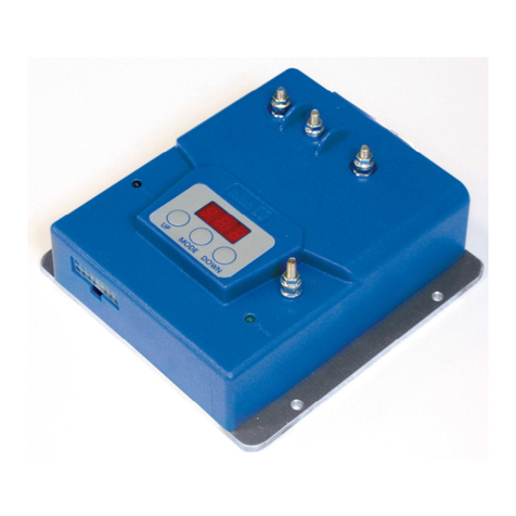
Italsea 7BL00100 User manual

7BL00100 | page 1
SERVICE MANUAL | rev 1 - 02/2021
7BL00100
MICROPROCESSOR CONTROLLER
FOR BRUSHLESS MOTORS
English

page 2 | 7BL00100
CONTENTS
1. SAFETY INSTRUCTIONS 3
2. INTRODUCTION 4
2a. Features 4
2b. Mechanical drawing 5
2c. Wiring diagram 6
3. CONNECTIONS 7
3a. J1-35 AMPSEAL CONNECTOR (p/n.776231-1) 7
3b. Power connections 8
4. CONTROLLER SETTING 8
4a. J7PROGLCD handheld programmer 8
5. TESTER MODE 9
6. ALARMS 10
7. PARAMETERS 11
8. ELECTROBRAKE DELAY MEANING 13
9. SPEED REFERENCE CALIBRATION 14
9a. Single ended calibration 14
9b. Voltage 0-Max calibration 14
9c. Wig-wag 1 and 2 calibration 14
10. BACKWARD SAFETY 15
11. OVERLOAD PROTECTION 15

7BL00100 | page 3
The controls described in this manual are to be considered and are sold as finished products to be installed only by
qualified personnel. Installation must be done in accordance with all safety regulations for the prevention of risks and
accidents applicable in the country of use.
Notes before energizing:
The controls for electric motors are able to produce high forces and rapid movements, therefore a high degree of
attention is required in their use, especially in the installation and application development phases.
The controls must be installed in a closed electrical panel so that none of its parts can be reached in the presence of
voltage.
Working on electric vehicles is potentially dangerous. Take all available precautions against burns, direct contact or
inhalation of acids, etc. (wear safety glasses, gloves, etc.).
Always follow the recommendations provided by the manufacturer of the batteries as they can deliver high currents in
the event of short circuits: completely disconnect the batteries before any intervention on the system (wiring operations,
checks on connections and various operations).
Controls for moving electric vehicles could cause you to lose control and create dangerous situations.
Disconnect the traction motor or lift the vehicle (also make other motors that could cause damage to persons or property
in appropriate safety) before starting any work on the circuits / connections.
The controls are protected against moisture by surface painting and direct circuit contacts with a partially open cover.
Place the controls in a dry, clean and ventilated position; avoid contact, in any form, with liquids such as water,
detergents, acids, oxides, etc.
The controls are high-powered devices and include various safety management of the electric vehicle.
The complete safety of the application cannot be left to control alone but must be integrated with the risk analysis of the
entire system by the manufacturer of the final machine.
Provide suitable fuses, battery disconnect switches (power switches, contactors, etc.), safety electro-brakes or
mechanical brakes and any other external component to safeguard the system and increase the safety level of the
electric vehicle.
In the event of a breakdown or serious alarm, assess in relation to the application whether the action of disconnecting
power from the motors is the best solution in terms of vehicle safety.
Avoid excessive length connections between controls, power source and motors.
The controls use the high-frequency PWM technology which may produce electromagnetic disturbances, partially already
filtered inside the circuits but which may not be sucient in the final system due to the complexity or execution of the
system itself. It is advisable to build the system with cables of reduced length and to appropriately separate the power
cables from the signal ones. If necessary, use shielded cables or external filters to reduce electromagnetic disturbances.
1. SAFETY INSTRUCTIONS

page 4 | 7BL00100
The 7BL00100 is a controller for brushless PM motors for 24V - 48V battery powered industrial-trucks.
The controller is equipped with two powerful microcontrollers: main microcontroller for digital control, alarms management,
parameters settings; second microcontroller for safety monitoring functions.
The controller is designed in accordance with the EC standards involved in the application.
2. INTRODUCTION
2a. Features
Supply (battery) 24V 36/48V
Rated current (60min) 45Arms 35Arms
Max current (1min) (@25°c) 110Arms 90Arms
Frequency 16kHz
Max heatsink temperature 90°C
Operating temperature -20°C / 50°C
Speed reference Voltage (0-5VDC/10VDC) / Potentiometer 1-10KΩ
Regenerative breaking Only for battery applications
On board main relay 24V-70A (rated) / 140A (overload 1')
Protection IP65
Communication CANBUS
Functional safety Designed in compliance to EN 1175-1
Emc EN61000-6-3; EN61000-6-2
Ul Designed in compliance to UL583 (pending)
Safety Reverse battery protection
Output short circuit protection
Mosfet short circuit protection
Thermal protection
Low voltage and overvoltage protection
Overcurrent protection (function of temperature)
Potenziometer and wiring fault
Emergency reverse input
Motor hall sensors / encoder failure
Motor temperature sensor (optional)
Electro-brake management

7BL00100 | page 5
2b. Mechanical drawing
Fix the controller with all the screws on a metal surface (aluminum if possible) to reduce the heat and so for longer
working time.

page 6 | 7BL00100
2c. Wiring diagram

7BL00100 | page 7
3. CONNECTIONS
Pin 1: Positive potentiometer supply (output from the board).
Pin 2: Potentiometer cursor (input to the board).
Pin 3: Negative potentiometer supply (output from the board).
Pin 4: Analog input (Vmax).
Pin 5: Digital input (Backward safety switch).
Pin 6: Digital input (Disable).
Pin 7: Digital input (Mode).
Pin 8: Digital input (Forward switch).
Pin 9: Digital input (Backward switch).
Pin 10: Inputs common (output from the board; around 15Vdc).
Pin 11: Key input (usually +Battery, used to turn on the board).
Pin 12: Hour meter output (active at around 15Vdc when the motor is driven).
Pin 13: Programmer RXD.
Pin 14: Programmer TXD.
Pin 15: Not used.
Pin 16: Not used.
Pin 17: Encoder serial I/O.
Pin 18: Encoder clock.
Pin 19: Encoder chip select.
Pin 20: Horn output (when active is connected to –Battery).
Pin 21: Alarm led output (positive output for external led).
Pin 22: +VB positive common for electro-brake/horn
Pin 23: Electro-Brake output (when active is connected to –Battery).
Pin 24: CAN-H interface.
Pin 25: CAN-L interface.
Pin 26: Positive supply output for Can, Programmer, etc. (+5Vdc).
Pin 27: Negative supply for Can, Programmer etc. (-Battery).
Pin 28: Hall sensors positive supply (around +15Vdc).
Pin 29: Hall A or Enc Z input.
Pin 30: Hall B or Enc SIN-P input.
Pin 31: Hall C or Enc COS-P input.
Pin 32: Negative supply (-Battery).
Pin 33: Motor temperature probe analog input.
Pin 34: Enc CHA or SIN-N input.
Pin 35: Enc CHB or COS-N input.
3a. J1-35 AMPSEAL connector (p/n.776231-1)

page 8 | 7BL00100
Power connections (+Battery, -Battery, Motor U, V, W), are made with screws:
M5 X 12mm (max 3.5Nm)
4. CONTROLLER SETTING
LCD 16X2 Displays parameters, alarms and measures
UP Key Rolls up parameters and increases values
MODE Key Confirms a selection and the change of value
UP Key Rolls down parameters and decreases values
At power-on, handheld programmer displays the “Tester Mode” pages. In these pages, you’ll find speed reference input,
actual speed, output current, battery voltage, overload status, internal aluminum heat-sink temperature, digital inputs and
hall/encoder status, motor temperature, hour-meter and software release. Pushing the buttons “UP” and/or “DOWN”, you
can move cyclically from one visualization to the other.
To start the programming function push the button “MODE”, and the first parameter will appear; pushing the “UP” button
the number of the parameter will be increased and with the “DOWN” button the number will be decreased. To select a
parameter, push the button “MODE”: you will enter in the change menu; change the parameter value with the buttons “UP”
and “DOWN”, then confirm the value with the button “MODE”; at this point you can again move through the parameters.
To return to the tester menu push together the buttons “MODE” and “UP”. Modified parameters values are saved when you
come back to tester menu.
In case of alarm, the programmer displays the alarm number.
Controller parameters can be modified through an external programmer (7PROGLCD handheld programmer or Programmer
key and mobile app). We will describe the handheld programmer, the interface is exactly the same if using the mobile app.
3b. Power connections
4a. 7PROGLCD handheld programmer

7BL00100 | page 9
5. TESTER MODE
SPEED REFERENCE
##.#V ####rpm
CURRENT ###Arms
SPEED #####rpm
BATTERY VOLTAGE
##.#Volt
OVERLOAD LEVEL
##% (at ##Arms)
HEATSINK TEMP.
##°C ###°F
J1: #,#,..
ENC: #,#,#,#,#
HOURMETER
#####hrs, ##min
MOTOR TEMP.
##°C ###°F
SOFTWARE RELEASE
7BL00100_0.0
Speed reference in Volt (potentiometer) and in rpm.
Actual motor current (Arms) and speed (rpm).
Battery voltage (Volt).
Overload level (%), actual current level (Arms).
Heat-sink temperature (in °C and °F).
Main connector active inputs (connector pin number);
Hall and encoder status (uppercase, lowercase).
Working hours and minutes.
Motor temperature (in °C and °F).
Software release.
The quantities visualized in the programmer are the following:

page 10 | 7BL00100
Handheld programmer displays failures or alarms: in the following table there is the list, the meaning of these alarms, and, if
possible, how to solve the problem.
Number Description What to do
01 Forward or backward switch closed at power on Open the switch
02 Not used -
03 Potentiometer fault Check wirings
04 Reference out of neutral at power on Move to neutral position or calibrate potentiometer
05 Over-temperature Wait to cool the controller
06 Power stage Change the controller
07 Over-current Control motor connections; eventually change the controller
08 Power fuse, relay Check power connections, fuse and relay; eventually change the
controller
09 Under-voltage Check battery charge status
10 Over-voltage Check the battery
11 Overload protection Check motor parameters: rated current and overload time
12 Disable switch on Check the switch
13 Key o sequence detected Check key connection
14 E² prom fail Check parameters; if the alarm is repeated, change the controller
15 Over-speed Speed too high
16 Hall/Encoder fail Check the hall sensors or the encoder and their connections
6. ALARMS

7BL00100 | page 11
NMin Def Max Description
0 0 0 1 Default parameter setting (see note 0)
10.5 0.5 10.0 Acceleration time from zero to max speed [sec]
20.5 0.5 10.0 Deceleration time to reverse from max speed to zero [sec]
30.5 1.0 10.0 Deceleration time to stop from max speed to zero [sec]
410 200 1000 Minimum speed [rpm]
5100 3000 10000 Maximum speed with no load [rpm]
610 100 100 Forward maximum speed [% of max speed]
710 100 100 Backward maximum speed [% of max speed]
824 48 48 Nominal battery voltage [Volt]
950 75 100 Low battery limit [% of nominal battery voltage]
10 10 40 50 Nominal current [Arms]
11 20 90 95 Maximum current [Arms]
12 100 110 120 Boost current [% of maximum current]
13 10 30 120 Overload protection time [s]
14 010 15 Boost time [s]
15 SE SE F-B Reference type (see note 1)
16 30 100 500 Potentiometer dead band [mV]
17 24 24 48 Electro-brake voltage [V]
18 0.0 1.0 30.0 Electro-brake delay [s]
19 10 70 100 Mode 1 current limit [% of current limit]
20 10 50 100 Mode 1 maximum speed [% of max speed]
21 03.0 5.0 Backward safety time [s]
22 330 50 Backward safety speed [% of max speed]
23 90 120 150 Motor maximum temperature [°C]
24 CW CW CCW Motor direction (see note 2)
25 NO NO NC Disable input configuration (see note 3)
26 NO NC NC Backward safety input configuration (see note 3)
27 NO NO NC Multi-mode input configuration (see note 3)
28 PD PD PU Disable input pull-up/down (see note 4)
29 PD PD PU Backward safety input pull-up/down (see note 4)
30 PD PD PU Multi-mode input pull-up/down (see note 4)
31 PD PD PU Forward direction input pull-up/down (see note 4)
32 PD PD PU Backward direction input pull-up/down (see note 4)
33 ENA ENA DIS Enable alarm 01 (see note 5)
34 ENA ENA DIS Enable alarm 03 (see note 5)
35 ENA ENA DIS Enable alarm 04 (see note 5)
36 ENA ENA DIS Enable alarm 12 (see note 5)
37 0 0 30000 Password to access reserved parameters (see note 6)
7. PARAMETERS

page 12 | 7BL00100
NMin Def Max Description
38 160 30000 Current loop proportional gain
39 115 30000 Current loop integral gain
40 1100 30000 Speed loop proportional gain
41 120 30000 Speed loop integral gain
42 10 300 500 Speed filter time constant
43 080 30000 Flux weakening integral gain
44 195 100 Anti-windup for small movements gain
45 1 4 32 Motor number of polar couples
46 030 30000 Motor stator resistance [Ohm/1000]
47 020 30000 Motor synchronous inductance [Hen/100000]
48 0180 30000 Motor permanent magnets flux [Web/10000]
49 0 0 30000 Not used
50 NOR NOR REV Hall sensors active status (see note 7)
51 DIS DIS E+R Encoder enable (see note 8)
52 16 32 256 Encoder pulses per revolution per channel
53 10 30 1000 Speed dead-band [% of minimum hardware speed]
54 0 0 30000 Not used
55 800 1000 1200 Bus voltage reading adjustment [1/1000]
56 800 1000 1200 Motor current reading adjustment [1/1000]
57 NOR NOR REV Reference direction (in wig-wag) (see note 7)
58 0 0 4095 Max potentiometer backward [bit]
59 0320 4095 Stop potentiometer [bit]
60 03520 4095 Max potentiometer forward [bit]
61 0 0 3599 Hour-meter: seconds [s]
62 0 0 60000 Hour-meter: hours [h]
63 0 0 60000 Number of switches o
Note 0: To reset all parameters to their default value, write 1 in par. 0; at reset the default parameters values will be loaded.
Note 1: Single Ended (SE): potentiometer with two direction switches;
0-Vmax (0-VM): analogical voltage signal with two direction switches;
Wig-Wag 1 (WW1): potentiometer with central stop position and enable switch;
Wig-Wag 2 (WW2): potentiometer with central stop position, without enable switch;
Forward/Backward (F-B): fixed speed (given by parameters 5 and 6) selected with two direction switches.
Note 2: Clockwise (CW), Counter-clockwise (CCW).
Note 3: Normally Open (NO), Normally Closed (NC).
Note 4: Pull Down (PD), Pull Up (PU).
Note 5: Enable(ENA), Disable (DIS).
Note 6: Password value (ask to your Italsea reference).
Note 7: Normal (NOR), Reversed (REV).
Note 8: Disabled (DIS), Enabled (ENA), Enabled + Reversed (E+R).

7BL00100 | page 13
8. ELECTROBRAKE DELAY MEANING
Controller supplies the electro-brake coil when the motor is running: the coil is powered-o with delay when the speed
reference and direction switches are in stop position. The value of the delay is regulated by parameter 15.
Brake ON
Brake OFF
Motor ON
Motor OFF
Time
Time
BRAKE DELAY

page 14 | 7BL00100
When changing the speed reference selection parameter (par. 13), a special mode is entered to tune the input channel;
depending on the choice, you have dierent possibilities:
9. SPEED REFERENCE CALIBRATION
9a. Single ended calibration
9b. Voltage 0-Max calibration
9c. Wig-wag 1 and 2 calibration
CALIBRATION
STOP POS = ##.#V
CALIBRATION
STOP POS = ##.#V
CALIBRATION
STOP POS = ##.#V
CALIBRATION
MAX POS = ##.#V
CALIBRATION
MAX POS = ##.#V
CALIBRATION
MAXBW POS= ##.#V
CALIBRATION
MAXFW POS= ##.#V
Put the potentiometer in the zero position;
Press the MODE key to confirm.
Set the voltage reference at its stop value;
Press the MODE key to confirm.
Put the potentiometer in the zero position;
Press the MODE key to confirm.
Put the potentiometer in the max position;
Press the MODE key to confirm.
Set the voltage reference at its max value;
Press the MODE key to confirm.
Put the potentiometer in the max backward position;
Press the MODE key to confirm.
Put the potentiometer in the max forward position;
Press the MODE key to confirm.

7BL00100 | page 15
10. BACKWARD SAFETY
11. OVERLOAD PROTECTION
This function operates in backward direction as a safety function for the operator. It is realized by mean of a contact
which activates the function when switched: the machine will immediately decelerate (at 4 times the selected inversion
rate), will reverse the direction at a programmed speed for the programmed time (if the time is not zero), then it will stop.
The normal operation is re-activated resetting the reference input and the switch. The parameter to regulate this function
are par. 18 (backward safety time) and par. 19 (backward safety speed).
This protection is always active and is based on the three parameters: nominal current (par. 10, INOM; the current which can
be sustained indefinitely by the control) current limit (par. 11, IMAX; the maximum admitted current) and overload time (par.
12, TP; the protection base time). The protection works in this way: first, a value is calculated as:
MAX = TP(IMAX-INOM)²
then in runtime a value is constantly calculated:
VAL(t) = (IRMS (x) - INOM)² dx
∫t
0
where IRMS(t) is the actual current rms value. VAL(t) is clamped at zero if it becomes negative. When VAL(t) becomes
greater than MAX, the overload alarm is generated. The overload status is, in every moment, the following:
100 %
VAL (t)
MAX
Temperature influences the formula, reducing the integration time; if temperature TEMP(t) is higher than 50°C then the
following modification is applied to the formula:
∫t
0
VAL(t) = (1.0 + 0.1(TEMP(x) - 50)) (IRMS (x) - INOM)² dx
For example is temperature is 80°C, the time to alarm is reduced 4 times.

page 16 | 7BL00100
ITALSEA S.r.l.
Via Maestri del Lavoro 1/A | 36078 Valdagno | Vicenza | Italy
T +39 0445 431014 | F +39 0445 431048 | italsea@italseasrl.it | italseasrl.it amergroup.it
Table of contents
Other Italsea Controllers manuals
Popular Controllers manuals by other brands

Siemens
Siemens ECOFAST 3RK1303 S AA Series operating instructions

HALOGEN VALVE SYSTEMS
HALOGEN VALVE SYSTEMS Terminator Installation, operation and maintenance manual

IVAR
IVAR SFWC Installation and operating instructions

Sporlan
Sporlan Superheat Installation and operation instructions

AFRISO
AFRISO ARM ProClick instruction manual

Honeywell
Honeywell HCE80 Installation and operation