Cloud Drive CDC6 User manual

Version No.: CD/J_SMS_CDC6/20230414-01
MANUAL
For CDC6 Display
Cloud drive intelligent technology Co.,Ltd
No. 6, Yuxi Road, Pukou District, Nanjing, Jiangsu Province, China

Cloud drive intelligent technology Co.,Ltd
Empower and serve the global eBike industry
Business Cooperation
PREFACE
Dear users:
In order to make you have better operation experience of the e-bike, please read the
CDC6 MANUAL carefully before using. We will guide you to learn the detailed operation
steps of CDC6 display, including the mounting steps and functions. Meanwhile, this
MANUAL will help you find the solutions to the possible malfunctions.

www.clouddrive.tech
Empower and serve the global eBike industry
Business Cooperation
CONTENT
1. Product Introduction .........................................................................................................3
2. Technical Parameter ........................................................................................................4
3. Appearance&Dimensions ................................................................................................ 4
4. Button Definition ...............................................................................................................5
5. Installation Instruction ...................................................................................................... 6
6. Operation Instruction ........................................................................................................7
7. General Setting .............................................................................................................. 10
8. Cycling Mode Switch ......................................................................................................15
9. Connectors Definition .....................................................................................................16
10. FAQ ..............................................................................................................................17
11. Quality Assurance & Warranty Scope ..........................................................................17
Annex.: Error Code Definition Table .................................................................................. 18
Cloud drive intelligent technology Co.,Ltd
Empower and serve the global eBike industry
Business Cooperation
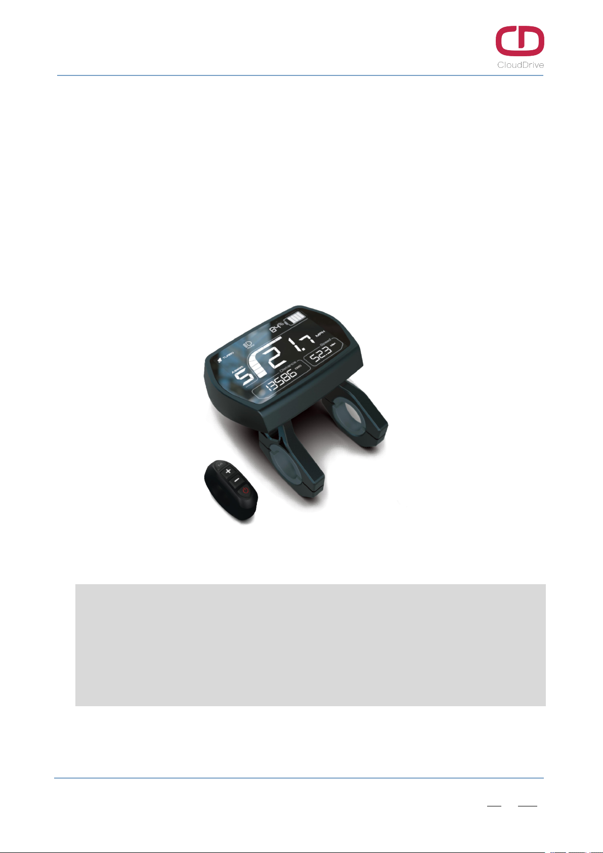
1. Product Introduction
CDC6 display adopts 3.5’’ LCD screen, and equip with the light and beautiful buttons, exquisite
appearance with matte black. The display interface frame is clear, double-layers printed circuit
board(PCB), nylon bracket, and ABS shell (The ABS material is allowed for normal use at temperature
ranging from -20°C to 60°C, meanwhile, it can also guarantee excellent mechanical properties.)
The same display can widely match the battery of voltage 24V/33V/36V/48V/52V, meanwhile,
integrated 24V/33V/36V/48V/52V headlight ON/OFF function.
Figure1-1 Product appearance
Main Functions:
Trip mileage and total mileage indication / Speed indication / Light indication / PAS level setting /
Residual battery capacity indication / Error code indication / Km/h and MPH switch / Wheel
diameter setting / USB charging / 6km/h walk assistance / Bluetooth connection(optional)
www.clouddrive.tech
Empower and serve the global eBike industry
Business Cooperation
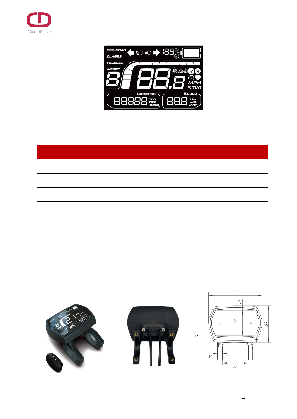
Figure1-2 All icons indication interface
2. Technical Parameter
Name Technical Parameter
Rated Voltage 24V/33V/36V/48V/52V
Rated Current 24V/19mA, 33V/16mA, 36V/15.5mA, 48V/14.5mA, 52V/14.4mA
Ambient Temperature -20°C ~ +60°C
Ambient Humidity 0 ~ 100%RH
Protection Level IP65
Visible Angel of Screen Horizontal 160°, Vertical 160°
Table1 - Technical Parameter Sheet
3. Appearance &Dimensions
The standard bracket diameter is Ø31.8mm, we can provide the reduction sleeve of Ø22.2mm and
Ø25.4mm, to adapt to different handlebar size.
Figure3-1 Product dimensions
Other manuals for CDC6
1
Table of contents
Other Cloud Drive Bicycle Accessories manuals

Popular Bicycle Accessories manuals by other brands


Specialized
Specialized Elite CylcoComputer user manual

Sigma
Sigma BC 16.16 manual

Playcore
Playcore Dero Setbacks installation instructions

VDO Cyclecomputing
VDO Cyclecomputing x3dw instruction manual

Cateye
Cateye RAPID X2 manual

buratti meccanica
buratti meccanica Clorofilla Trail Use and maintenance manual


