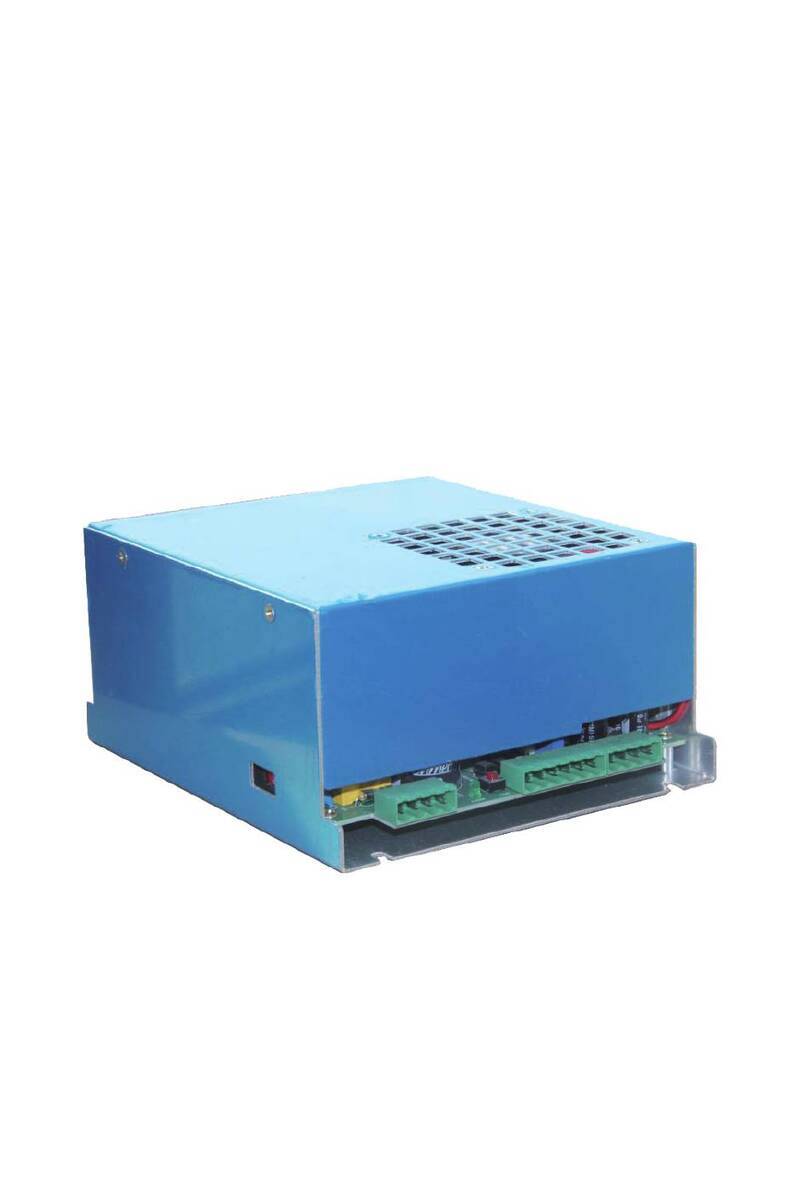
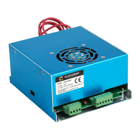
Cloudray MYJG-40 User manual

Power Supply MYJG-40 User Manual
www.cloudraylaser.com 1
First of all, thanks a lot for you to choose our laser power supply products. To make good
use of our product, please read this manual carefully in advance. Model of this product is
MYJG-40 NW
40W Power Supply for CO2Laser Tubes
Model: MYJG-40 NW
I. Main Features
1. Good Compatibility: It can be applicable to 40W laser tubes manufactured by
different factories.
2. High Performance: Fast response, Good engraving effect, it can prolong the service
life of laser tube significantly.
3. Open Circuit Protection Function: When the earth connection is under good
situation, power can be short time work in open state. It can avoid the laser tube burst
damage caused by laser power supply, prolong the laser tube's service life.
4. Test Mode: One button to test the output laser manually(50% Max Power).
5. Application: Sculpture and cut acrylic, fabric, double color sheet, rubber etc.
II. Specification
Input
Input Voltage AC220V or AC110V (Switch Control)
AC Frequency 47-440HZ
Max Input Power 250W
Max Input Current 5A
Output Maximum Output Voltage DC 23KV
Maximum Output Current DC 20mA
Efficiency ≥90%(Full Load)
Mean Time Between
Failure (MTBF) ≥10000H
Response Speed ≤1ms(From the switch signal is given to the output current up to 90% of the
setting current)
www.cloudraylaser.com
www.cloudraylaser.com
www.cloudraylaser.com
www.cloudraylaser.com
www.cloudraylaser.com
www.cloudraylaser.com
www.cloudraylaser.com
www.cloudraylaser.com
www.cloudraylaser.com
www.cloudraylaser.com

Power Supply MYJG-40 User Manual
www.cloudraylaser.com 2
Withstand Voltage Input-Output, Input-Enclosure: AC1500V 10mA 60S; Output (negative pole) is
connected with machine Enclosure.
Weight 1.3kg
Environment Working Temperature:(-10~40℃), Relative Humidity (RH)≤90%
Cooling Way Force-Air Cooling (FAC)
III. Operation Instruction
1. Laser Tube Connection: (Referring to Power Supply and Laser Device's Connection
Diagram)
High voltage terminal (HV+) of MYJG-40NW power supply should be connected to the
positive pole of CO2 laser device. Current circuit of the power supply shall be connected
to negative pole (laser output terminal) of laser device, through an ampere meter or
directly.
2. Connection of Control Signal
The control signal shall be reliably connected to control terminal of the power supply
MYJG-40 NW, after connecting the DAC output signal and TTL signal of external
computer with the power supply, the laser device shall work as expected. If the laser lamp
can not work properly, should check the control signal is correct or not(include check the
voltage specification and logic), if use PWM control as power control, make sure f≥20KHz,
amplitude (peak value) ≤5V, Check and make sure protection switch WP connection is
correct at same time.
3. Voltage of Power Input:
MYJG-40W's power input of the power supply shall be 220VAC/50Hz. This power
supply can be adjusted for 110V or 220V.
4. Others:
A group of protection switches are also reserved for detection of water switch, fan
switch, open-enclosure protection and so on.
Caution:
1) Water cooling system should be working properly when switching on laser device.
2) Circuit of high voltage output should not be open! [High voltage output terminals
(positive and negative poles) shall be properly connected to positive and negative
poles of laser device, respectively.]
3) Attentions should be given to avoid any electric shock after the power supply being
switched off. (The Insulation Safety Requirements should be 40KV between the
terminal of output and "G")
4) Well-grounded three-pole receptacle should be used to the supply power. The
enclosure should be well grounded to avoid electric shock.
www.cloudraylaser.com
www.cloudraylaser.com
www.cloudraylaser.com
www.cloudraylaser.com
www.cloudraylaser.com
www.cloudraylaser.com
www.cloudraylaser.com
www.cloudraylaser.com
www.cloudraylaser.com
www.cloudraylaser.com

Power Supply MYJG-40 User Manual
www.cloudraylaser.com 3
IV. The Instruction of Power Supply and Laser Wiring Diagram and
Terminal
Terminal Definition as follows:
www.cloudraylaser.com
www.cloudraylaser.com
www.cloudraylaser.com
www.cloudraylaser.com
www.cloudraylaser.com
www.cloudraylaser.com
www.cloudraylaser.com
www.cloudraylaser.com
www.cloudraylaser.com
www.cloudraylaser.com

Power Supply MYJG-40 User Manual
www.cloudraylaser.com 4
Caution :
WP G
Figure 1 Figure 2
1) WP input terminal can use water switch or fan switch's test terminal, please pay
attention that WP is through optocoupler connected with ground (G) as (figure2), not as
(figure 1).
2) PWM Control: Requirements of the PWM frequency f ≥20 kHz, amplitude (peak value)
≤ 5V
Function of Control Interface:
TH TL WP IN Laser Output
unconnected
Low(≤0.3V)
Low(≤0.3V)
0-5V or PWM Output laser
Power: Pmin~Pmax
Low(≤0.3V) unconnected Output about 40% laser
High(≥3V) Any value (ok) No laser
High(≥3V)
Unconnected
0-5 or PWM Output laser, Pmin~Pmax
Low(≤0.3V) Unconnected Output about 40% laser
Low(≤0.3V) Any value (ok) No laser
Any value (ok) Any value (ok) High(≥3V) No laser
VI. The connection of power supply and control board
1.Recommended connection: High-level light control
TH TL WP G IN 5V
手动出光
WP
G
High-level light control "G"
Control Board
Water Detection
Manual laser operating
FG (Power supply
and enclosure of
laser machine)
Computer system
www.cloudraylaser.com
www.cloudraylaser.com
www.cloudraylaser.com
www.cloudraylaser.com
www.cloudraylaser.com
www.cloudraylaser.com
www.cloudraylaser.com
www.cloudraylaser.com
www.cloudraylaser.com
www.cloudraylaser.com

Power Supply MYJG-40 User Manual
www.cloudraylaser.com 5
2. Recommended connection: Low-level light control
TH TL WP G IN 5V
0~5V
VII. Check the power supply worked properly or not manually
Make sure the power supply and laser tube wiring correct. Unplug the control pins
and then press the ”TEST” button to test laser tube fire or not. The power supply and laser
tube can be judged working properly via this method.
VIII. Common Fault Detection and Ruled Out
Problem Cause Estimation Solution
Trip After
Power On
1. External Wiring:
AC and FG reverse
connection
Check if AC and FC
misplaced
Connected correctly
according to
Instruction
2. External Wiring:
Short circuit
between AC and AC
Use multimeter to check if
short circuit between AC
and AC.
Rewiring, and avoid
short circuit
3. Internal Wiring:
Short circuit
between AC and AC
or AC and FG
Send back factory for
maintenance
4. Other Causes
AC Power
On but Fan
of Power
1. Fan socket is
loose.
Laser emission when
manual test.
Open enclosure and
tighten socket.
2. Fan damaged
Laser emission when
manual test.
Change fan or send
back factory for
maintenance
Low-level light control G laser power control
Control Board
Output interface of
water detection
0~5V analog signal or
5V amplitude PWM
signal (f ≥20KHz)
Manual laser operating
Computer System
www.cloudraylaser.com
www.cloudraylaser.com
www.cloudraylaser.com
www.cloudraylaser.com
www.cloudraylaser.com
www.cloudraylaser.com
www.cloudraylaser.com
www.cloudraylaser.com
www.cloudraylaser.com
www.cloudraylaser.com

Power Supply MYJG-40 User Manual
www.cloudraylaser.com 6
Supply Does
not work
3. Fuse is burned.
No laser emission when
manual test.
Contact with us for
repair.
AC power on
but no laser
emission
1. Control wire
connected wrong
Check if wire is connected
correctly according to
Operation Instruction
Rewiring correctly
2. Internal
connector is loose.
Open outside case and
check Tighten connector.
3. Protection switch
on but on water
through or water
through switch is
broken.
Voltage>0.5V between
“WP”and”G”
Water through or
change water
through switch.
4. Wrong output
laser signal
Voltage between”TH ”
and “G” should<3V when
When laser-open
controlled by high level Replace CNC card or
change GND.
Voltage between"TL" and
“G” should>3V when
laser-open controlled by
low level.
5. Power control
signal is 0.
Voltage between “IN”and
“G” is 0.
Increase voltage
between “IN”and “G”.
6. Fuse is burned.
Fan does not work Send back factory for
maintenance
7. Others
Send back factory for
maintenance
Laser
emission at
all times
1.When “TL” control
laser: short circuit
between”TL ”and
“G”.
Voltage between”TL ”
and “G” =0
disconnected
between”TL ”and
“G”.
2. Circuit is broken. Send back factory for
maintenance
3. Switch of manual
test laser emission is
broken.
Change switch of
manual test laser
emission.
4. Other causes. Send back factory for
maintenance
Current is
not
increased
1. AC voltage is too
low
Output current is always at
5mA around.
Use AC voltage
regulator.
Send back factory for
maintenance
2. Power supply
and laser Device is
not connected very
well
3. Power control
signal from CNC
card is not
connected very well
with “IN”.
Output current is always at
10mA around. Re-connected
3. Potentiometer of
power is broken.
Output current is not
stable.
Change
potentiometer.
4. PWM frequency
or amplitude is not
suitable.
Change PWM
frequency or
amplitude.
www.cloudraylaser.com
www.cloudraylaser.com
www.cloudraylaser.com
www.cloudraylaser.com
www.cloudraylaser.com
www.cloudraylaser.com
www.cloudraylaser.com
www.cloudraylaser.com
www.cloudraylaser.com
www.cloudraylaser.com

Power Supply MYJG-40 User Manual
www.cloudraylaser.com 7
5. Internal
Transformer is
broken. Output current is always at
5mA around Send back factory for
maintenance
6. One circuit does
not work.
7. Others
Laser head
is not stable
during
working.
GND is not
connected well.
Connect earth wire of
CNC card,enclosure
of power supply, with
enclosure of laser
machine.
Laser
emission is
not stable
during
working.
When two
laser head
works, action
abnormal.
www.cloudraylaser.com
www.cloudraylaser.com
www.cloudraylaser.com
www.cloudraylaser.com
www.cloudraylaser.com
www.cloudraylaser.com
www.cloudraylaser.com
www.cloudraylaser.com
www.cloudraylaser.com
www.cloudraylaser.com
Table of contents
Other Cloudray Power Supply manuals
Popular Power Supply manuals by other brands

LC-POWER
LC-POWER GP4 Series manual
Pulsar
Pulsar EN54-5A28 manual
WAGO
WAGO EPSITRON COMPACT Power 787-1212 Operating and assembly instructions

eta plus
eta plus ELC N12 Technical documentation
Elenco Electronics
Elenco Electronics XP-620K Assembly and instruction manual
SLAT
SLAT AESI C24 operating instructions
