CLOUDVOCAL ISOLO CHOICE User manual
ISOLO CHOICE
INTRODUCTION
ISOLO CHOICE series is an advanced stage performance system, developed and
launched by CLOUDVOCAL after the first generation of ISOLO PURE. To better suit
different needs, this generation of microphones has been newly designed and adjusted
for each different instruments to capture the most truly nuances. In addition, the receiver
has also been substantially upgraded to maximize its capability and performance. Now
with integrated preamp, EQ and effects, plus precise control of balance all in one pack-
age, allows you to focus just on creating music. Whether you want to connect directly to
the amplifier, effect pedals or straight into mixing console, our new ISOLO CHOICE stage
receiver is up to all tasks.
WARNING
This product is made of precision machinery and
electronic parts. Please keep it in cool and dry
environment at all times. Rain, moisture, liquid and
other minerals will corrode the electronic circuit.
Continued use under abnormal conditions may result
in fire or electric shock due to heat.
If the microphone power supply or the ISOLO
CHOICE stage receiver is damaged, do not attempt
to repair it by yourself. Please have it handed over to
a qualified technician or dealer.
When using an AC adapter, do not use it in a location
where it can get wet or exposed to moisture. A
damaged AC adapter or USB cable may cause a
malfunction or fire. Please hand it over to a profes-
sional technician or dealer.
WARRANTY
Within 12 months from the date of purchase, if the
product fails under normal use conditions during the
warranty period, CLOUD VOCAL will repair or
replace the product free of charge.
Accessories that comes with the product is not
covered by the same warranty. If there’ s malfunc-
tions in the accessories come with the package,
please contact us within 7 days of purchase.
Please keep your order number and proof of
purchase for future warranty service.
Warranty service does not include the following:
improper installation, operation, cleaning, mainte-
nance, accident, damage, misusage, abuse, natural
wear or other accidents, actions, faults or negligence
causing a malfunction, etc.
ISOLO CHOICE
Pilot’s Handbook of ISOLO CHOICE English
01
FCC Statement

ISOLO CHOICE
Pilot’s Handbook of ISOLO CHOICEEnglish
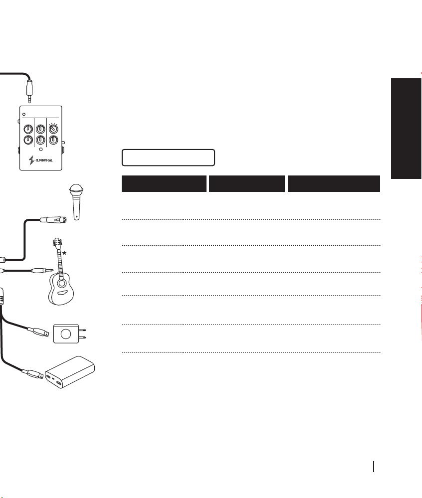
Connection diagram
PRODUCT SPECIFICATION
OUTPUT
NEAR
FAR
INPUT
DC 9V
LINE / MIC
EQ
BASS
TREBLE MASTER BLEND
EFX PARAM
®
MUTE
SYNC IN ANT SYNC OUT
AUX IN
ISOLO EFFECT
1
-
+
-
+
-
+
-
+
D W
234
GAIN EFX
EQ
BASS
TREBLE MASTER BLEND
EFX PARAM
®
MUTE
SYNC IN ANT SYNC OUT
AUX IN
ISOLO EFFECT
1
-
+
-
+
-
+
-
+
D W
234
GAIN EFX
02
°C°C
Specification Sheet
EQ
BASS
TREBLE MASTER BLEND
EFX PARAM
®
MUTE
SYNC IN ANT SYNC OUT
AUX IN
ISOLO EFFECT
1
-
+
-
+
-
+
-
+
D W
234
GAIN EFX
ISOLO CHOICE
Pilot’s Handbook of ISOLO CHOICE English
03

QUICK START GUIDE
Screw in the antenna to the stage receiver and plug
in the power. At this time, the power indicator flashes
blue meaning it’s ready to be paired.
Place the microphone close to the stage receiver
(about 2 cm away), and press the pairing button
shortly.
When the transmitter is showing green indicates that
the two are paired.
Attach the microphone on to different instru-
ments: please refer to its mount manual
which comes with your ISOLO model.
Please scan the QR-Code to see
the video reference.
Press the power switch of the microphone
transmitter for 5 seconds, and the pairing
indicator starts to flash.
Step1 Setup CHOICE stage receiver Step 2 Turn on Microphone
Step 3 Pair Microphone Step 4
(1)
(1)
(3)
(2)
(2)
(2)
2cm
ISOLO CHOICE
Pilot’s Handbook of ISOLO CHOICEEnglish
04
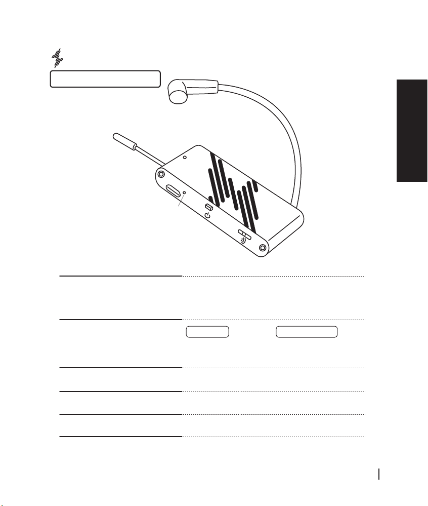
PRODUCT SPECIFICATION
Microphone Transmitter
Power / Pairing button
Charging Terminal
Charging /
Low Power Indicator
Charging method:
1. Connect the USB charging cable to the terminal
2. Connect the other end of the USB charging cable to
the power transformer
*Please charge the microphone for 2 hours for the first time.
Preamp Gain Three modes: low, medium and high.
Feel free to adjust its gain when needed.
Red light on charge or low battery
Red light off Full battery
Studio-grad Capsule
Low-rebound Gooseneck
Power / Pairing Indicator
ISOLO CHOICE
Pilot’s Handbook of ISOLO CHOICE English
05

ANT
SYNC IN
SYNC OUT
ISOLO CHOICE Stage Receiver
EQ
BASS
TREBLE MASTER BLEND
EFX PARAM
®
MUTE
SYNC IN ANT SYNC OUT
AUX IN
ISOLO EFFECT
1
-
+
-
+
-
+
-
+D W
234
GAIN EFX
OUTPUT
NEAR
FAR
INPUT
DC 9V
LINE / MIC
PRODUCT SPECIFICATION
SYNC IN / SYNC OUT Connection disgram
-
-
EQ
BASS
TREBLE MASTER BLEND
EFX PARAM
ISOLO EFFECT
1
+
+
-
+
-
+
D W
234
GAIN EFX EQ
BASS
TREBLE MASTER BLEND
EFX PARAM
ISOLO EFFECT
1
+
+
-
+
-
+
D W
234
GAIN EFX EQ
BASS
TREBLE MASTER BLEND
EFX PARAM
ISOLO EFFECT
1
+
+
-
+
-
+
D W
234
GAIN EFX EQ
BASS
TREBLE MASTER BLEND
EFX PARAM
ISOLO EFFECT
1
+
+
-
+
-
+
D W
234
GAIN EFX
Using 2-4 isolo systems
at the same time: It’ s
recommended to leave 2m
distance between each
receiver. Please connect
each receiver with sync
cables as following
illustration.
ISOLO CHOICE
Pilot’s Handbook of ISOLO CHOICEEnglish
06

MUTE
AUX IN 1/8 inch 3.5 mm stereo jack socket.
Auxiliary stereo input and mono-mixed out
(CD/MP3 player)
Connector for a footswitch.
mono jack, 1/8 inch (3.5mm) Function:
Switch ON = channel muted
The mute pedal is available as additional purchase.
BASS Bass control of ISOLO mic signal
+/- 6dB @200hz (shelf type)
TREBLE Treble control of ISOLO mic signal +/- 6dB @8khz
(shelf type)
ISOLO ISOLO mic Gain control +/- 6dB
MASTER Master volume control
Mute~0dB
BLEND Controls the balance of dry and wet signal.
Turn the knob counterclockwise all the way
for 100% dry signal.
EFX PARAM 1. Room Reverb:
When effect position 1 is selected,
EFX PARAM adjusts the Decay Time of Room Reverb.
2. Hall Reverb:
When effect position 2 is selected,
EFX PARAM adjusts the Decay Time of Hall Reverb.
3. Chorus:
When effect position 3 is selected,
EFX PARAM adjusts the LFO rate of Chorus effect.
4. Delay:
When effect position 4 is selected,
EFX PARAM adjusts the Delay Time of Delay effect.
EFX Digital effect processor with 4 presets
1= Room reverb
2 = Hall reverb
3 = Chorus
4 = Delay
Note: effects on ISOLO mic signal only.
ISOLO CHOICE
Pilot’s Handbook of ISOLO CHOICE English
07

DC INPUT
Power supply input range (7-9 Volt DC)
There are two methods of supply power to ISOLO
receiver using power DC7V Converter Cable:
1. Connect it to power adapter(5V/2A), then plug it into
a wall socket.
2. Directly connect it to a power bank.
LINE/MIC GAIN
0dB~40dB
POWER INDICATOR
Battery level high Battery level medium Battery level low
(needs to be charged)
OUTPUT
1. 1/4 inch (6.3mm) balanced TRS output
(T = positive (+), R = negative (-), S = ground)
2. 1/4 inch (6.3mm) unbalanced TS output
(T = positive (+), S = ground)
LINE/MIC INPUT
Two kind of input
High impedance input for instrument pickups* and
line-level sources
1. 1/4 inch (6.3mm) balanced TRS input
(T = positive (+), R = negative (-), S = ground)
2. 1/4 inch (6.3mm) unbalanced TS input
(T = positive (+), S = ground)
FAR/NEAR
Near mode 15 meters Line-of-sight.
Far mode 30 meters Line-of-sight.
*Actual distance depending on the environment
*recommended passive pickups to avoid interference
the power consumption of battery on microphone
transmitter will change along with the distance of the choice receiver
Two kind of output
Blue light Green light Red light
Near
Far
5hrs - 3.5hrs 3.5hrs - 0.5hrs <0.5hrs
7hrs - 4.5hrs 4.5hrs - 0.5hrs <0.5hrs

Federal Communication Commission Interference Statement
This equipment has been tested and found to comply with the limits for a Class B
digital device, pursuant to Part 15 of the FCC Rules. These limits are designed to
provide reasonable protection against harmful interference in a residential
installation.
This equipment generates, uses and can radiate radio frequency energy and, if not
installed and used in accordance with the instructions, may cause harmful
interference to radio communications. However, there is no guarantee that
interference will not occur in a particular installation. If this equipment does cause
harmful interference to radio or television reception, which can be determined by
turning the equipment off and on, the user is encouraged to try to correct the
interference by one of the following measures:
. Reorient or relocate the receiving antenna.
. Increase the separation between the equipment and receiver.
. Connect the equipment into an outlet on a circuit different from that to which the
receiver is connected.
. Consult the dealer or an experienced radio/TV technician for help.
FCC Caution: To assure continued compliance, any changes or modifications not
expressly approved by the party responsible for compliance could void the user's
authority to operate this equipment. (Example - use only shielded interface cables
when connecting to computer or peripheral devices).
FCC Radiation Exposure Statement
This equipment complies with FCC RF radiation exposure limits set forth for an
uncontrolled environment. This equipment should be installed and operated with a
minimum distance of 20 centimeters between the radiator and your body.
This transmitter must not be co-located or operating in conjunction with any other
antenna or transmitter.
The antennas used for this transmitter must be installed to provide a separation
distance of at least 20 cm from all persons and must not be co-located or operating
in conjunction with any other antenna or transmitter.
This device complies with Part 15 of the FCC Rules. Operation is subject to the
following two conditions: (1) this device may not cause harmful interference, and (2)
this device must accept any interference received, including interference that may
cause undesired operation.
Table of contents
Other CLOUDVOCAL Musical Instrument manuals


