CLS ECLS User manual

Please read all instructions carefully before installing this luminaire.
This wet-location cold cathode luminaire comes from the factory completely pre-assembled.
Some disassembly is required in order to wire the luminaire(s) to line voltage, and to install
the lamp(s). This luminaire must be installed by a licensed electrician. All wiring and installation
methods must be in compliance with the National Electric Code and all applicable local codes.
Model ECLS
Single lamp luminaire
ECLS Manual 6-08
c2008 Cathode Lighting Systems
Cathode Lighting Systems Inc.
8020 Queenair Drive
Gaithersburg, MD 20879
Ph: (800) 551-5012
Fax: (301) 963-3050
Email: [email protected]
INSTALLATION MANUAL
Model ECLS
Exterior Wet Location Single-Lamp Cathode Light Strip
Suitable for outdoor wet locations
Opertating temperature range: 10 F to 100 F
E168380
Pat. 6,454,431
INDEX
Page 1: Receiving your shipment & removing the polycarbonate lens
Page 2: Mounting the luminaire
Page 3: Attaching conduit to the luminaire
Page 4: Installing luminaires end to end
Page 5: Wiring Diagram & Electrical Information
Page 6: Installing the Lamp & Reinstalling the Polycarbonate Lens
Page 7: System Checklist & Troubleshooting

1/8” to 3/16”
Receiving your shipment
Please follow the instructions below. All shipments are F.O.B. Gaithersburg, MD.
If any damage has occured, you must immediately alert the shipper so that a claim may
be filed.
How to remove the polycarbonate lens
Loosen, (but do not remove) the screws which attach the two full-length retaining clips on each side of the luminaire. The
retaining clips can then be lifted up and tilted back from the luminaire allowing the tethered lens to be removed.
Approximately 1/8” - 3/16” of the screw thread will be visible below the shoulder of the lens fastener. This will allow the
lens fastener to be moved up and out of the way to remove the lens.
8020 Queenair Drive
Gaithersburg, MD 20879
Ph: (800) 551-5012
Fax: (301) 963-3050
Email: [email protected]
ECLS Manual 6-08
c2008 Cathode Lighting Systems
1) Remove the luminaire from its packaging.
IMPORTANT: Please take all precautions to ensure that no water or moisture enters this luminaire during
installation. These luminaires are IP65 rated, and are water, and vapor tight. Any moisture that enters the
luminaire while the lens is removed, will be trapped inside after reinstallation of the lens. It is strongly
advised to install this product only when dry weather conditions prevail.
Page 1

Place the luminaire in the desired location, and using the 1/4" x
3/4” mounting slots and the appropriate fasteners, mount the
luminaire. Stainless steel fasteners are required, and should be
rated, so that each fastener can fully support the entire weight of
the luminaire.
IMPORTANT: If mounting holes necessitate penetrating a
waterproof roofing or exterior surface, the installation contractor will
be responsible for maintaining the waterproof integrity of the roof or
exterior surface.
Mounting the luminaire
This luminaire is designed to
be securely fastened on each
of its four corners.
Rubber sealing plug, do not
remove unless it is being
replaced with a liquid tight
fitting, or being coupled to an
adjacent luminaire.
4
2
3
1
Page 2
8020 Queenair Drive
Gaithersburg, MD 20879
Ph: (800) 551-5012
Fax: (301) 963-3050
Email: [email protected]
ECLS Manual 6-08
c2008 Cathode Lighting Systems
Insert the fastener through the luminaire and into the
hole and fasten tightly enough to secure the luminaire,
but loosely enough to allow movement back and forth
through the slotted mounting bracket. This movement
will be necessary for the procedure described on page
4 “Mounting Luminaires End to End”. Repeat for the
remaining three holes

After the luminaire has been securely mounted in the desired location, conduit which will contain the primary wiring must
be attached. A UL-Listed waterproof conduit and the appropriate conduit fittings must be used.
IMPORTANT: The UL-Listed rubber plugs installed in the ends of every luminaire are only to be removed if they are to be
replaced by the proper liquid tight conduit adaptor, or if another luminaire is to be coupled to an ajoining luminaire.
ATTACHING CONDUIT TO THE END OF THE
LUMINAIRE:
Remove one rubber plugs at the end of the luminaire, and
install a standard Liquid Tight fitting into the 7/8” hole at
the end of the luminaire.
Attach Liquid Tight conduit to the luminaire in one of
the following ways:
ATTACHING CONDUIT TO THE UNDERSIDE OF THE
LUMINAIRE:
If it is required that the conduit penetration location be
concealed, a standard 7/8" hole may be drilled in the back
of the luminaire (making sure the hole is drilled at least 6
inches away from the ballast or any internal parts or
wiring) and a standard liquid tight conduit connector may
be installed.
Remove the snap-fit cover and the two wiring compartment covers at each end of the luminaire.
Note: If only a single luminaire is being installed, only one wiring compartment cover need be removed.
Conduit
UL-Listed
liquid tight
conduit
and conduit
fitting.
7/8" hole
UL-Listed liquid tight
conduitand conduit fitting
Conduit
locknut
Snap-fit cover
wiring
compartment
Attaching conduit to the lumimaire Page 3
8020 Queenair Drive
Gaithersburg, MD 20879
Ph: (800) 551-5012
Fax: (301) 963-3050
Email: [email protected]
ECLS Manual 6-08
c2008 Cathode Lighting Systems

IMPORTANT: These luminaires maintain a watertight seal between each other via an EPDM rubber washer (each
luminaire is provided with one washer). It is imperative that this joint be tightened prior to final tightening of the
fasteners. If fasteners are tightened first, it will be impossible to draw the two luminaires together properly and create a
waterproof seal. The slotted stainless-steel mounting tabs allow the fasteners to be partially installed while still allowing
the movement required to properly tighten the waterproof joint between. When this joint has been properly drawn
together, the fasteners may be tightened.
1” long x 1/2” (trade size) galvanized
electrical nipple and locknuts (to be
provided by installing electrical
contractor)
Place the ends of the luminaire together, and tighten the locknuts untill the two luminaires are drawn together very
securely. When the EPDM washer is properly compressed, the gap between to two luminaire ends should be
approximately 1/32”.
EPDM washer (provided by
Cathode Lighting Systems)
conduit locknut
conduit locknut
Installing luminaires end to end Page 4
8020 Queenair Drive
Gaithersburg, MD 20879
Ph: (800) 551-5012
Fax: (301) 963-3050
Email: [email protected]
ECLS Manual 6-08
c2008 Cathode Lighting Systems
stainless mounting tab
1/32” spacing between
fixtures when locknuts
are tightened securely,
compressing the EPDM
washer

LUMINAIRE WIRING & ELECTRICAL INFORMATION
Red & Black to hot line
White to neutral line
Green/Yellow to ground
IMPORTANT: CIRCUITS MUST BE DE-ENERGIZED WHEN PERFORMING ANY WIRING / INSTALLATION
8020 Queenair Drive
Gaithersburg, MD 20879
Ph: (800) 551-5012
Fax: (301) 963-3050
Email: [email protected]
ECLS Manual 6-08
c2008 Cathode Lighting Systems
Ballasts are available either in 120 volt or 277 volt models.
Primary amperage is as follows:
120-volt model: 1.4 amps
277-volt model: .7 amps
Maximum number of luminaires allowed on one 20-amp
circuit:
120-volt operation: 11 luminaires
277-volt operation: 22 luminaires
Wiring Diagram & Electrical information Page 5

Once the lens has been properly positioned, return the two
lens retaining clips back to the vertical position and tighten
sequentially around the perimeter of the fixture. Tighten all
screws halfway, and then sequentially tighten all screws
until the bottom of the clip is drawn against the fixture (pic)
The exterior cathode light strip may now be energized.
Carefully replace the polycarbonate lens, making sure that the edges of the ends of the lens rest evenly at each end
within the gasketed channel.
Correct
End of lens sits evenly
spaced within the gasket
Incorrect
End of lens is too close to the
outside wall of the gasket
channel.
Incorrect
End of lens is too close to the
inside wall of the gasket
channel.
J. Reinstalling the polycarbonate lens
Installing the Lamp & Reinstalling the Polycarbonate Lens Page 5
I. Installing the lamp
Snap the lamp in the lampholders, making sure good electrical contact is occurring at each end.
Using a flathead screwdriver, slide the lamp-lock clips into the locked position.
8020 Queenair Drive
Gaithersburg, MD 20879
Ph: (800) 551-5012
Fax: (301) 963-3050
Email: [email protected]
ECLS Manual 6-08
c2008 Cathode Lighting Systems

Lamp will not light
The ballast in this luminaire is equiped with integral open-circuit and ground-fault protection. It the luminaire is energized
without a lamp in place, the ballast will turn itself off automatically. To reset the ballast, the primary power must be turned
off, and then on again. If the luminaire still does not light, the lamp could be inoperable. Contact the factory for further
assistance.
Lamps are dim or do not turn on in cold weather
These lamps and fixtures are intended to operate in continuous temperatures of 10 F and above. It is recommended that
in cold climates (10 F to 32 F), the fixures be left on continuously (day and night), as lamp starting can be problematic
during after temperature dips into the single-digits (and below). Leaving lamps burning continuously during cold weather
will alleviate potential starting issues caused by cycling lamps on in the eveining and off in the daytime.
Lamps will also not exhibit full intensity at temperatures below 32 F, and may appear very dim at temperatures below 10 F.
Lamp exhibits a rolling or spiraling effect
Turn the luminaire off for five seconds, and then turn off for two seconds. Repeat this procedure 5-10 times. The rolling or
spiraling should stop. If the lamp continues to roll or spiral, remove the lamp from the luminaire, wipe it with a clean rag,
and reinsert the lamp 180 degrees from its previous orientation. If the lamp continues to appear unstable, contact the
factory for further assistance.
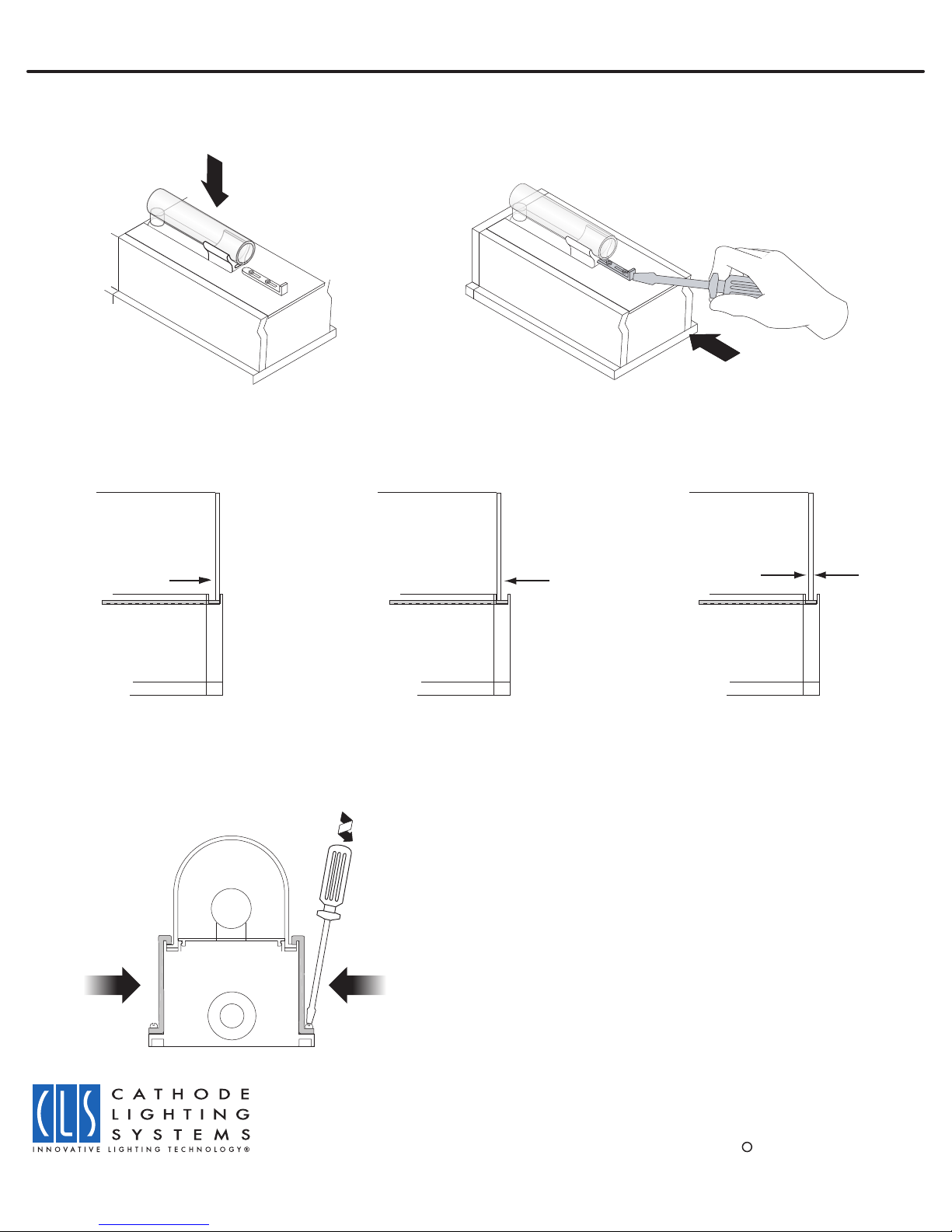
Condensation appears inside luminaire
Polycarbonate lens is not seated correctly, and/or lens retaining clips are not seated fully into channel which contains the
lens lip and the silicone gasket, or EPDM Rubber washer between luminaires is not compressed properly.
System Checklist & Troubleshooting Page 7
SYSTEM CHECKLIST (PRIOR TO ENERGIZING)
The circuit may be energized after the following items have been completed:
A. Luminaires are properly fastened and lamps are properly installed and seated within the lampholders
B. Lens is installed and is properly compressing the silicone gasket
C. All primary connections have been made with the proper electrical connectors
8020 Queenair Drive
Gaithersburg, MD 20879
Ph: (800) 551-5012
Fax: (301) 963-3050
Email: [email protected]
ECLS Manual 6-08
c2008 Cathode Lighting Systems
TROUBLESHOOTING
Table of contents
Other CLS Outdoor Light manuals
Popular Outdoor Light manuals by other brands

Maxim Lighting
Maxim Lighting 30042CDCF manual

Coopers of Stortford
Coopers of Stortford Pre Lit Autumn Wreath Instructions for use

Licatec
Licatec Edgelight PLM III Series Assembly instruction

VIBIA
VIBIA Break Assembly instructions

Dale Tiffany
Dale Tiffany TA100353 Assembly instructions

WE-EF
WE-EF RMC320 LED Installation and maintenance instructions

ACR Electronics
ACR Electronics RCL-50 LED Product support manual

Lasvit
Lasvit Michael Young CLOVER 14X051-00 manual

3B SCIENTIFIC PHYSICS
3B SCIENTIFIC PHYSICS U8475400 instruction sheet

Cooper Lighting
Cooper Lighting Halo SWL0540W instruction manual

Plusrite
Plusrite PLS-30W quick start guide

evolution lighting
evolution lighting 19305-000 quick start guide